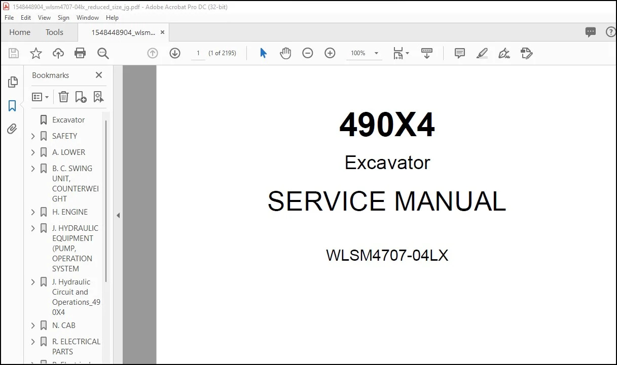
Linkbelt 490X4 Excavator Service Manual WLSM4707-04LX – PDF DOWNLOAD
Original price was: $86.95.$33.95Current price is: $33.95.
Linkbelt 490X4 Excavator Service Manual WLSM4707-04LX – PDF DOWNLOAD
Description
Linkbelt 490X4 Excavator Service Manual WLSM4707-04LX – PDF DOWNLOAD
FILE DETAILS:
Linkbelt 490X4 Excavator Service Manual WLSM4707-04LX – PDF DOWNLOAD
Language : English
Pages : 2195
Downloadable : Yes
File Type : PDF
Size: 151 MB
IMAGES PREVIEW OF THE MANUAL:
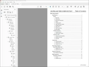
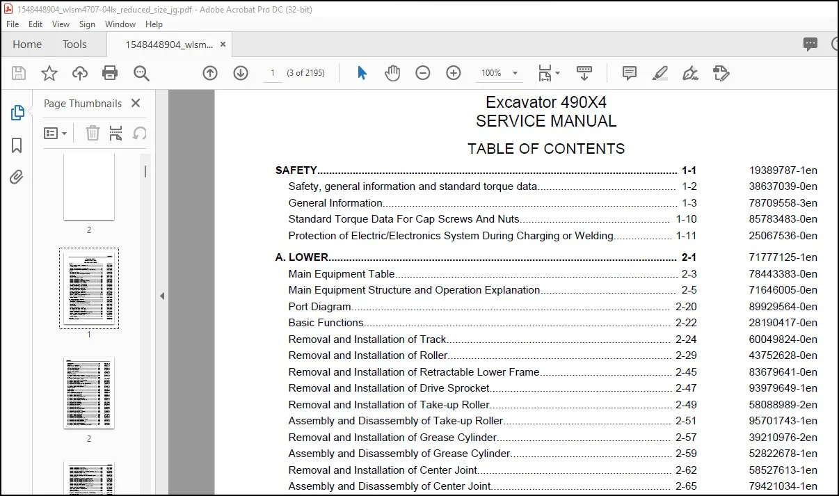
TABLE OF CONTENTS:
Linkbelt 490X4 Excavator Service Manual WLSM4707-04LX – PDF DOWNLOAD
SAFETY 1-1 19389787-1en
Safety, general information and standard torque data 1-2 38637039-0en
General Information 1-3 78709558-3en
Standard Torque Data For Cap Screws And Nuts 1-10 85783483-0en
Protection of Electric/Electronics System During Charging or Welding 1-11 25067536-0en
A LOWER 2-1 71777125-1en
Main Equipment Table 2-3 78443383-0en
Main Equipment Structure and Operation Explanation 2-5 71646005-0en
Port Diagram 2-20 89929564-0en
Basic Functions 2-22 28190417-0en
Removal and Installation of Track 2-24 60049824-0en
Removal and Installation of Roller 2-29 43752628-0en
Removal and Installation of Retractable Lower Frame 2-45 83679641-0en
Removal and Installation of Drive Sprocket 2-47 93979649-1en
Removal and Installation of Take-up Roller 2-49 58088989-2en
Assembly and Disassembly of Take-up Roller 2-51 95701743-1en
Removal and Installation of Grease Cylinder 2-57 39210976-2en
Assembly and Disassembly of Grease Cylinder 2-59 52822678-1en
Removal and Installation of Center Joint 2-62 58527613-1en
Assembly and Disassembly of Center Joint 2-65 79421034-1en
Removal and Installation of Travel Motor 2-74 30970495-3en
Assembly and Disassembly of Travel Motor 2-79 51874242-3en
Maintenance Standards 2-113 16266917-1en
Pressure Measurement and Adjustment Procedures 2-120 83246188-1en
Drain Volume Measurement Procedures 2-121 72272769-0en
Air Bleed Procedure 2-123 76863098-0en
B C SWING UNIT, COUNTERWEIGHT 3-1 97410031-1en
Main Equipment Table 3-2 78443383-0en
Counterweight Removal System (Option) 3-3 10222557-0en
Main Equipment Structure and Operation Explanation 3-4 71646005-0en
Port Diagram 3-18 89929564-0en
Basic Functions 3-19 28190417-0en
Removal and Installation of Swing Unit 3-25 65912034-0en
Assembly and Disassembly of Swing Unit 3-28 77385530-1en
Assembly and Disassembly of Swing Motor 3-31 69583460-5en
Removal and Installation of Counterweight 3-49 36870479-1en
Removal and Installation of Counterweight Removal System 3-51 16329676-0en
Pressure Measurement and Adjustment Procedures 3-66 83246188-1en
Drain Volume Measurement Procedures 3-67 72272769-0en
Air Bleed Procedure 3-68 76863098-0en
H ENGINE 4-1 53979139-1en
Main Equipment Table 4-7 78443383-0en
Basic Functions 4-9 28190417-0en
Main Data 4-63 53916484-1en
Function, Structure, Operation 4-66 44871357-2en
Function, structure, operation (SCR) 4-128 27929211-1en
SCR Control System Inspection 4-158 78058558-1en
Explanation of SCR Operation 4-159 95238910-2en
Diagnosis for Each Symptom 4-161 21805842-1en
Symptom 4-166 19251071-0en
Functional Inspection 4-176 69663730-0en
Removal and Installation of Engine Assembly 4-185 72709793-0en
Removal and Installation of Fuel Cooler, Engine Intercooler, Radiator, and Oil
Cooler 4-189
28776642-0en
Removal and Installation of Turbo Charger 4-199 43042560-3en
Removal and Installation of EGR Valve (if equipped) 4-206 32547506-1en
Removal and Installation of Engine Hood 4-215 58805990-0en
Removal and Installation of SCR 4-220 96782610-0en
Removal and installation of Silicon Controlled Rectifier Catalyst 4-221 71913988-1en
Removal and Installation of Cylinder Head Cover 4-227 78412812-0en
Removal and Installation of Cylinder Block 4-272 75278091-0en
Lubrication System 4-323 70203119-0en
Cooling System 4-330 69949934-0en
Induction System 4-359 92865729-1en
Exhaust System 4-360 89869774-1en
Aux Emission Control Devices System 4-363 71618698-1en
Removal and Installation of Fuel Tank 4-375 27501984-0en
Removal and Installation of Urea Pump 4-379 37078590-0en
Removal and Installation of Urea Solution Tank 4-381 17610219-2en
Removal and Installation of Fuel Supply Pump 4-383 18906180-0en
Removal and Installation of Common Rail Assembly 4-399 24718817-0en
Removal and Installation of Injector 4-410 31274146-0en
Removal and installation of Idle Gear 4-423 88541792-1en
Removal and installation of Crankshaft 4-463 37684987-1en
Removal and installation of Piston 4-514 88466996-1en
Removal and installation of Camshaft 4-552 39727464-1en
Removal and installation of Flywheel 4-561 49328546-1en
Removal and installation of Rocker Arm Shaft 4-563 51224917-1en
Removal and installation of Front Cover 4-571 84313582-1en
Removal and installation of Intake Throttle Valve 4-578 59420164-1en
Removal and Installation of Starter Motor 4-579 14131940-0en
Removal and Installation of Alternator 4-589 53939335-1en
Removal and Installation of Glow Plug 4-596 45292928-0en
Removal and installation of Fuel Filter 4-604 35283611-1en
Removal and installation of Fuel Filter Element 4-606 28242594-1en
Removal and installation of Fuel temperature sensor 4-608 13119135-1en
Removal and installation of Pressure limiter 4-610 91840001-1en
Removal and installation of Fuel pressure sensor 4-613 54310813-1en
Removal and Installation of Fuel filter pressure 4-620 41943855-1en
Removal and Installation of Engine coolant temperature sensor 4-621 72826315-1en
Removal and Installation of CKP sensor 4-625 92654264-1en
Removal and Installation of CMP sensor 4-626 11296113-1en
Removal and Installation of Oil pressure sensor 4-627 71303987-1en
Removal and installation of Pressure Sensor/Boost Temperature Sensor 4-628 81952792-1en
Removal and Installation of IMT sensor 4-629 42362214-1en
Removal and installation of MAF and IAT sensor 4-630 91296734-1en
Removal and installation of Charge Air Cooler Temperature Sensor 1 4-632 66306841-1en
Sampling Procedure 4-633 38464543-0en
Removal and Installation of Exhaust gas temperature sensor 4-634 83790917-1en
Removal and installation of EGR Gas Temperature Sensor 1 4-636 79377911-1en
Removal and installation of EGR Gas Temperature Sensor 2 4-638 52797245-1en
Removal and installation of EGR Gas Temperature Sensor 3 4-640 21958060-1en
Removal and installation of EGR Gas Temperature Sensor 4 4-641 33582395-1en
Removal and installation of NOx Sensor 4-643 70645643-1en
Removal and Installation of Exhaust gas temperature sensor 3 4-646 10879967-1en
Removal and installation of DEF Sensor 4-648 46935705-1en
Engine-related Diagnostic Trouble Code List 4-649 99630402-2en
Engine-side Trouble 4-658 16577120-0en
Data Reference Values 4-838 49437404-1en
J HYDRAULIC EQUIPMENT (PUMP, OPERATION SYSTEM VALVE) 5-1 68276312-1en
Main Equipment Table 5-5 78443383-0en
Basic Functions 5-11 28190417-0en
Port Diagram 5-33 89929564-0en
Hydraulic Pump 5-47 71826868-0en
Hydraulically-operated fan pump 5-73 68383864-0en
Hydraulically-operated fan motor 5-85 44610296-0en
Control Valve 5-99 56107455-0en
5 Stack Solenoid Valve Operation Explanation 5-122 87031521-0en
Upper Pilot Valve (remote control valve) 5-123 25350181-0en
Travel Pilot Valve (remote control valve) 5-128 39613125-0en
Cushion Valve 5-134 11949795-0en
Selector Valve (2-way) 5-139 32379090-0en
Direction Valve (3-direction) 5-142 30102944-0en
Electromagnetic Relief Valve 5-145 64662087-0en
Removal and Installation of Hydraulic Reservoir 5-149 15386488-0en
Removal and Installation of Hydraulic Pump 5-153 63383358-0en
Removal and Installation of Pump coupling 5-157 20592604-1en
Removal and Installation of Control Valve 5-159 26600348-0en
Removal and Installation of Travel Remote Control Valve 5-164 89439321-1en
Removal and Installation of Operation Remote Control Valve 5-168 94100775-1en
Installation and Removal of 5 Stack Solenoid Valve 5-176 20298065-0en
Removal and Installation of Cushion Valve 5-178 85137039-1en
Removal and Installation of Hydraulically-Operated Fan Pump 5-181 33174481-0en
Removal and Installation of Hydraulically-Operated Fan Motor 5-183 74292113-0en
Procedures for Assembly and Disassembly of Hydraulic Pump Main Unit 5-185 59889726-0en
Pump Main Unit Maintenance Standards 5-191 54580195-0en
Regulator Maintenance Standards 5-203 86103035-0en
Assembly and Disassembly of Control Valve 5-219 72743984-0en
Procedures for Assembly and Disassembly of Operation Remote Control Valve 5-245 80887250-1en
Procedures for Assembly and Disassembly of Travel Remote Control Valve 5-256 23581849-0en
Assembly and Disassembly of Cushion Valve 5-269 38410900-0en
Pressure Measurement and Adjustment Procedures 5-273 83246188-1en
Hydraulic Pump Flow Measurement Procedures 5-292 62052930-0en
Air Bleed Procedure 5-296 76863098-0en
Sampling Procedure 5-297 38464543-0en
Hydraulic Equipment Layout 5-298 81702821-0en
Overall View 5-299 68446286-0en
N CAB 6-1 25744330-1en
Removal and Installation of Operator’s Seat 6-2 64020993-1en
Removal and Installation of Cab Assembly 6-3 58647651-2en
Removal and Installation of Wiper 6-8 56260865-1en
Removal and Installation of Cab Front Glass 6-9 85033204-1en
Removal and Installation of Right-side Window Glass 6-11 20957683-1en
Removal and Installation of Door (Upper) Sash Glass 6-16 88900412-1en
Window Lock Adjustment Procedures 6-21 70190809-2en
Removal and Installation of Housing Guardrail 6-23 76560728-0en
Tightening Torque 6-25 46004929-1en
R ELECTRICAL PARTS 7-1 18400544-1en
Basic Functions 7-3 28190417-0en
Service Support 7-27 30914595-0en
Connection Connector Pin Layout 7-144 81470562-0en
Sequence Circuit Diagram 7-146 95593007-0en
Electrical Equipment Layout Diagram 7-166 22799429-0en
Removal and Installation of Wiper Controller 7-208 48783449-1en
Removal and Installation of Wiper Motor 7-209 60222373-1en
Removal and Installation of ECM 7-211 37149170-1en
Removal and Installation of Main Controller 7-212 35550813-0en
Removal and Installation of DCU 7-213 63452717-0en
Removal and Installation of Monitor 7-214 51691250-2en
Removal and Installation of Rear View Camera 7-216 36493336-1en
Removal and Installation of Side Camera (Right) 7-217 76098215-1en
Removal and Installation of Side Camera (Left) 7-218 63078153-1en
Removal and Installation of FVM Controller 7-219 75916970-1en
How to Set FVM 7-220 33847448-0en
Air Conditioner Overall Diagram 7-225 70666574-0en
Assembly and Disassembly of Unit 7-263 80491730-0en
Removal and Installation of Compressor 7-266 68506379-0en
Removal and Installation of Condenser 7-268 60506286-0en
Removal and Installation of Receiver Dryer 7-269 76369168-0en
Work Precautions 7-270 23051033-6en
V ATTACHMENTS 8-1 84181484-1en
Main Equipment Table 8-3 78443383-0en
Maintenance Standards 8-4 16266917-1en
Removal and Installation of Bucket Cylinder 8-12 94363778-1en
Removal and Installation of Arm Cylinder 8-16 50905387-2en
Removal and Installation of Boom Cylinder 8-21 26434239-1en
Procedures for Operation/Assembly and Disassembly of Hydraulic Cylinder 8-26 71081947-0en
HBCV 8-64 83156430-0en
Port Diagram 8-71 89929564-0en
Air Bleed Procedure 8-73 76863098-0en
Removal and Installation of HBCV 8-75 95886020-0en
Removal and Installation of Arm HBCV 8-76 94563380-0en
Removal and Installation of Boom HBCV 8-78 35772541-0en
Removal and Installation of Bucket 8-81 11050117-1en
Removal and Installation of Bucket Link 8-83 99170709-1en
Removal and Installation of Arm 8-85 68554640-1en
Removal and Installation of Boom 8-87 50501770-0en
Z OTHER 9-1 68145258-1en
Change from Type 6 9-5 58609717-1en
Specifications (Standard Lower Specifications) 9-14 24837701-0en
Specifications (Retract Lower Specifications) 9-20 19907170-0en
Specifications (High Soil Volume Specifications) 9-26 80555062-0en
Arm Dimension 9-32 31180251-0en
Main Unit Weight 9-42 12343363-0en
Bolt Size and Torque Table 9-46 30335582-1en
Overall View 9-51 34508823-0en
WORK RANGE DIAGRAM 9-61 20473064-1en
New Machine Performance Judgment Table 9-82 72039816-1en
FLUIDS AND LUBRICANTS 9-92 18850575-0en
Main-Unit-related Diagnostic Trouble Code List 9-93 70292507-4en
Main Unit-side Trouble 9-96 14139955-0en
List of special tools 9-217 95642836-0en
Paint Colors 9-258 42774539-0en
Abbreviation 9-260 40185832-2en
DESCRIPTION:
Linkbelt 490X4 Excavator Service Manual WLSM4707-04LX – PDF DOWNLOAD
General Information:
Cleaning
Clean the metal parts with a cleaning fluid or steamer that meets standards. (except for the bearing) After cleaning the parts, let them dry well and inject oil into all parts. Inject oil into the bearing after letting it dry.
Inspection
When disassembling parts, inspect all the parts. Replace any worn or damaged parts. Inspect them thoroughly to prevent early failures.
Bearing
If the bearing is loose, replace it. Install the bearing after air drying it.
Needle bearing
When inserting the needle bearing, be careful not to scratch it.
Inject grease into the location where the needle bearing is to be inserted.
Gear
Check for any wear or damage.
Oil seals, O-rings, gaskets
Always install new oil seals, O-rings, and gaskets. Inject grease into the locations where oil seals and O-rings are to be inserted.
Shaft
Check for any wear or damage. Check the oil seal on the bearing and damaged shaft.
Service parts
Install genuine LBX Link-Belt service parts. When ordering parts, see the parts catalog that has genuine LBX Link-Belt part numbers listed. Any failures caused by installing a nongenuine part are not covered by the warranty.
Lubrication (fuel, hydraulic oil)
- Use oils from specified manufacturers or the ones specified in the operator’s manual or Service Manual.
- Any failures caused by using other fuel or hydraulic oil than specified are not covered by the warranty.
Customer Support: [email protected]
https://vimeo.com/770179698
PLEASE NOTE:
- This is the SAME exact manual used by your dealers to fix your vehicle.
- The same can be yours in the next 2-3 mins as you will be directed to the download page immediately after paying for the manual.
- Any queries / doubts regarding your purchase, please feel free to contact [email protected]
S.V