Linkbelt 750X4 Excavator Service Manual WLSM7007-03LX – PDF DOWNLOAD
Original price was: $86.95.$34.95Current price is: $34.95.
Linkbelt 750X4 Excavator Service Manual WLSM7007-03LX – PDF DOWNLOAD
Description
Linkbelt 750X4 Excavator Service Manual WLSM7007-03LX – PDF DOWNLOAD
FILE DETAILS:
Linkbelt 750X4 Excavator Service Manual WLSM7007-03LX – PDF DOWNLOAD
Language : English
Pages : 2146
Downloadable : Yes
File Type : PDF
Size: 90 MB
IMAGES PREVIEW OF THE MANUAL:
DESCRIPTION:
Linkbelt 750X4 Excavator Service Manual WLSM7007-03LX – PDF DOWNLOAD
General Information:
Cleaning
Clean the metal parts with a cleaning fluid or steamer that meets standards. (except for the bearing) After cleaning the parts, let them dry well and inject oil into all parts. Inject oil into the bearing after letting it dry.
Inspection
When disassembling parts, inspect all the parts. Replace any worn or damaged parts. Inspect them thoroughly to prevent early failures.
Bearing
If the bearing is loose, replace it. Install the bearing after air drying it.
Needle bearing
When inserting the needle bearing, be careful not to scratch it.
Inject grease into the location where the needle bearing is to be inserted.
Gear
Check for any wear or damage.
Oil seals, O-rings, gaskets
Always install new oil seals, O-rings, and gaskets. Inject grease into the locations where oil seals and O-rings are to be inserted.
Shaft
Check for any wear or damage. Check the oil seal on the bearing and damaged shaft.
Service parts
Install genuine LBX Link-Belt service parts. When ordering parts, see the parts catalog that has genuine LBX Link-Belt part numbers listed. Any failures caused by installing a nongenuine part are not covered by the warranty.
Lubrication (fuel, hydraulic oil)
- Use oils from specified manufacturers or the ones specified in the operator’s manual or Service Manual.
- Any failures caused by using other fuel or hydraulic oil than specified are not covered by the warranty.
TABLE OF CONTENTS:
Linkbelt 750X4 Excavator Service Manual WLSM7007-03LX – PDF DOWNLOAD
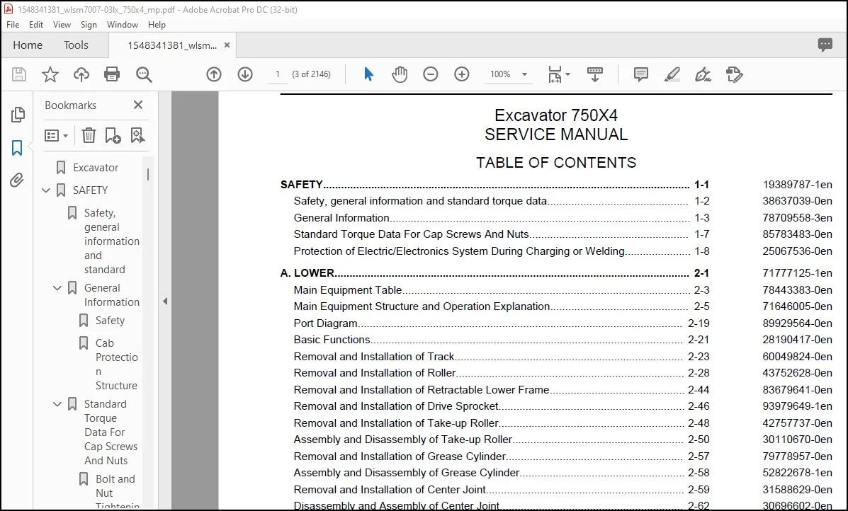
SAFETY 1-1 19389787-1en
Safety, general information and standard torque data 1-2 38637039-0en
General Information 1-3 78709558-3en
Standard Torque Data For Cap Screws And Nuts 1-7 85783483-0en
Protection of Electric/Electronics System During Charging or Welding 1-8 25067536-0en
A LOWER 2-1 71777125-1en
Main Equipment Table 2-3 78443383-0en
Main Equipment Structure and Operation Explanation 2-5 71646005-0en
Port Diagram 2-19 89929564-0en
Basic Functions 2-21 28190417-0en
Removal and Installation of Track 2-23 60049824-0en
Removal and Installation of Roller 2-28 43752628-0en
Removal and Installation of Retractable Lower Frame 2-44 83679641-0en
Removal and Installation of Drive Sprocket 2-46 93979649-1en
Removal and Installation of Take-up Roller 2-48 42757737-0en
Assembly and Disassembly of Take-up Roller 2-50 30110670-0en
Removal and Installation of Grease Cylinder 2-57 79778957-0en
Assembly and Disassembly of Grease Cylinder 2-58 52822678-1en
Removal and Installation of Center Joint 2-59 31588629-0en
Disassembly and Assembly of Center Joint 2-62 30696602-0en
Removal and Installation of Travel Motor 2-64 38515111-0en
Assembly and Disassembly of Travel Motor 2-69 10926045-0en
Maintenance Standards 2-126 16266917-1en
Pressure Measurement and Adjustment Procedures 2-133 83246188-1en
Drain Volume Measurement Procedures 2-135 72272769-0en
Air Bleed Procedure 2-137 76863098-0en
B C SWING UNIT, COUNTERWEIGHT 3-1 97410031-1en
Main Equipment Table 3-2 78443383-0en
Counterweight Removal System (Option) 3-3 10222557-0en
Main Equipment Structure and Operation Explanation 3-4 71646005-0en
Port Diagram 3-20 89929564-0en
Basic Functions 3-21 28190417-0en
Removal and Installation of Swing Unit 3-27 17863503-0en
Assembly and Disassembly of Swing Unit 3-30 27510692-0en
Assembly and Disassembly of Swing Motor 3-33 41206678-0en
Removal and Installation of Counterweight 3-49 89928330-0en
Removal and Installation of Counterweight Removal System 3-51 16329676-0en
Pressure Measurement and Adjustment Procedures 3-69 83246188-1en
Drain Volume Measurement Procedures 3-71 72272769-0en
Air Bleed Procedure 3-72 76863098-0en
H ENGINE 4-1 53979139-1en
Main Equipment Table 4-7 78443383-0en
Contents
1
Basic Functions 4-9 28190417-0en
Main Data 4-64 25982455-0en
Function, Structure, Operation 4-67 35773454-0en
Function, Structure, and Operation of Emission Control 4-129 93655279-0en
SCR Control System Inspection 4-160 78058558-1en
Operation Explanation of SCR 4-161 24084851-0en
Diagnosis for Each Symptom 4-163 21805842-1en
Symptom 4-168 19251071-0en
Functional Inspection 4-178 69663730-0en
Removal and Installation of Engine Assembly 4-186 50065651-0en
Removal and Installation of Fuel Cooler, Engine Intercooler, Radiator, and Oil
Cooler 4-190
28776642-0en
Removal and Installation of Turbo Charger 4-198 43042560-3en
Removal and Installation of EGR Valve (if equipped) 4-205 32547506-1en
Removal and Installation of EGR Cooler 4-216 76253396-0en
Removal and Installation of Engine Hood 4-227 58805990-0en
Removal and Installation of SCR 4-230 56785730-0en
Removal and installation of Silicon Controlled Rectifier Catalyst 4-232 71913988-1en
Removal and Installation of Cylinder Head Cover 4-238 78412812-0en
Removal and Installation of Cylinder Block 4-284 75278091-0en
Lubrication System 4-346 70203119-0en
Cooling System 4-371 69949934-0en
Induction System 4-392 92865729-1en
Exhaust System 4-393 89869774-1en
Aux Emission Control Devices System 4-396 71618698-1en
Removal and Installation of Fuel Tank 4-408 41598786-0en
Removal and Installation of Urea Pump 4-411 37078590-0en
Removal and Installation of Urea Solution Tank 4-413 25470603-0en
Removal and Installation of Fuel Supply Pump 4-415 18906180-0en
Removal and Installation of Common Rail Assembly 4-422 24718817-0en
Removal and Installation of Injector 4-438 31274146-0en
Removal and installation of Idle Gear 4-457 88541792-1en
Removal and installation of Crankshaft 4-494 37684987-1en
Removal and installation of Piston 4-556 88466996-1en
Removal and installation of Camshaft 4-600 39727464-1en
Removal and installation of Flywheel 4-610 49328546-1en
Removal and Installation of Flywheel housing 4-612 89917239-0en
Removal and Installation of Timing Gear Case 4-618 47755787-0en
Removal and installation of Rocker Arm Shaft 4-661 51224917-1en
Removal and installation of Intake Throttle Valve 4-669 59420164-1en
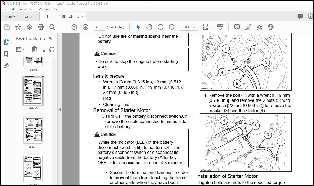
Removal and Installation of Starter Motor 4-670 14131940-0en
Removal and Installation of Alternator 4-679 10705840-0en
Removal and Installation of Glow Plug 4-687 45292928-0en
Removal and installation of Fuel Filter 4-697 35283611-1en
Removal and installation of Relief Valve 4-700 34135732-1en
Removal and installation of Fuel Filter Element 4-701 28242594-1en
Removal and installation of Fuel temperature sensor 4-703 13119135-1en
Removal and installation of Pressure limiter 4-705 91840001-1en
Contents
2
Removal and installation of Fuel pressure sensor 4-708 54310813-1en
Removal and Installation of Fuel filter pressure 4-709 41943855-1en
Removal and Installation of Engine coolant temperature sensor 4-710 72826315-1en
Removal and Installation of CKP sensor 4-714 92654264-1en
Removal and Installation of CMP sensor 4-715 11296113-1en
Removal and Installation of Oil Pressure Sensor 4-716 36716870-0en
Removal and installation of Pressure Sensor/Boost Temperature Sensor 4-717 81952792-1en
Removal and Installation of IMT sensor 4-718 42362214-1en
Removal and installation of MAF and IAT sensor 4-719 91296734-1en
Removal and installation of Charge Air Cooler Temperature Sensor 1 4-721 66306841-1en
Sampling Procedure 4-722 38464543-0en
Removal and Installation of Exhaust gas temperature sensor 4-723 83790917-1en
Removal and installation of EGR Gas Temperature Sensor 1 4-725 79377911-1en
Removal and installation of EGR Gas Temperature Sensor 2 4-727 52797245-1en
Removal and installation of EGR Gas Temperature Sensor 3 4-729 21958060-1en
Removal and installation of EGR Gas Temperature Sensor 4 4-731 33582395-1en
Removal and installation of NOx Sensor 4-733 70645643-1en
Removal and Installation of Exhaust gas temperature sensor 3 4-736 10879967-1en
Removal and installation of DEF Sensor 4-738 46935705-1en
Engine-related Diagnostic Trouble Code List 4-739 71159340-5en
Engine-side Trouble 4-746 16577120-0en
J HYDRAULIC EQUIPMENT (PUMP, OPERATION SYSTEM VALVE) 5-1 68276312-1en
Main Equipment Table 5-5 78443383-0en
Basic Functions 5-10 28190417-0en
Port Diagram 5-32 89929564-0en
Hydraulic Pump 5-45 71826868-0en
Hydraulically-operated fan pump 5-67 68383864-0en
Hydraulically-operated fan motor 5-79 44610296-0en
Control Valve 5-83 56107455-0en
5 Stack Solenoid Valve Operation Explanation 5-133 87031521-0en
Upper Pilot Valve (remote control valve) 5-134 25350181-0en
Travel Pilot Valve (remote control valve) 5-139 39613125-0en
Cushion Valve 5-145 11949795-0en
Selector Valve (2-way) 5-150 32379090-0en
Removal and Installation of Hydraulic Reservoir 5-153 63265119-0en
Removal and Installation of Hydraulic Pump 5-156 30001462-0en
Removal and Installation of Pump coupling 5-160 20592604-1en
Removal and Installation of Control Valve 5-162 84238257-0en
Removal and Installation of Travel Remote Control Valve 5-168 18742449-0en
Removal and Installation of Operation Remote Control Valve 5-171 94100775-1en
Removal and Installation of 5 Stack Solenoid Valve 5-179 75986443-0en
Removal and Installation of Cushion Valve 5-181 85137039-1en
Removal and Installation of Hydraulically-Operated Fan Pump 5-184 57612706-0en
Removal and Installation of Hydraulically-Operated Fan Motor 5-186 88010263-0en
Procedures for Assembly and Disassembly of Hydraulic Pump Main Unit 5-187 59889726-0en
Pump Main Unit Maintenance Standards 5-194 54580195-0en
Regulator Maintenance Standards 5-206 86103035-0en
Contents
3
Assembly and Disassembly of Control Valve 5-222 72743984-0en
Procedures for Assembly and Disassembly of Operation Remote Control Valve 5-267 80887250-1en
Procedures for Assembly and Disassembly of Travel Remote Control Valve 5-278 23581849-0en
Assembly and Disassembly of Cushion Valve 5-291 38410900-0en
Pressure Measurement and Adjustment Procedures 5-295 83246188-1en
Hydraulic Pump Flow Measurement Procedures 5-313 62052930-0en
Air Bleed Procedure 5-317 76863098-0en
Sampling Procedure 5-318 38464543-0en
Hydraulic Equipment Layout 5-319 81702821-0en
Overall View 5-320 54661492-0en
N CAB 6-1 25744330-1en
Removal and Installation of Operator’s Seat 6-2 64020993-1en
Removal and Installation of Cab Assembly 6-3 58647651-2en
Removal and Installation of Wiper 6-8 56260865-1en
Removal and Installation of Cab Front Glass 6-9 85033204-1en
Removal and Installation of Right-side Window Glass 6-11 20957683-1en
Removal and Installation of Door (Upper) Sash Glass 6-16 88900412-1en
Window Lock Adjustment Procedures 6-21 70190809-2en
Removal and Installation of Housing Guardrail 6-23 76560728-0en
Tightening Torque 6-25 46004929-1en
R ELECTRICAL PARTS 7-1 18400544-1en
Basic Functions 7-3 28190417-0en
Service Support 7-25 30914595-0en
Connection Connector Pin Layout 7-142 81470562-0en
Sequence Circuit Diagram 7-144 95593007-0en
Electrical Equipment Layout Diagram 7-159 63474288-0en
Removal and Installation of Wiper Controller 7-198 48783449-1en
Removal and Installation of Wiper Motor 7-199 60222373-1en
Removal and Installation of ECM 7-201 37149170-1en
Removal and Installation of Main Controller 7-202 35550813-0en
Removal and Installation of DCU 7-203 63452717-0en
Removal and Installation of Monitor 7-204 51691250-2en
Removal and Installation of Rear View Camera 7-206 36493336-1en
Removal and Installation of Side Camera (Right) 7-207 76098215-1en
Removal and Installation of Side Camera (Left) 7-208 63078153-1en
Removal and Installation of WAVES Controller 7-209 47142105-0en
How to set WAVES 7-210 47165795-0en
Air Conditioner Overall Diagram 7-214 70666574-0en
Assembly and Disassembly of Unit 7-254 80491730-0en
Removal and Installation of Compressor 7-257 68506379-0en
Removal and Installation of Condenser 7-259 67891228-0en
Removal and Installation of Receiver Dryer 7-260 76369168-0en
Work Precautions 7-261 23051033-6en
V ATTACHMENTS 8-1 84181484-1en
Main Equipment Table 8-2 78443383-0en
Maintenance Standards 8-3 16266917-1en
Removal and Installation of Bucket Cylinder 8-11 45056298-0en
Removal and Installation of Arm Cylinder 8-15 97393520-0en
Removal and Installation of Boom Cylinder 8-20 21411463-0en
Procedures for Operation/Assembly and Disassembly of Hydraulic Cylinder 8-25 71081947-0en
Port Diagram 8-70 89929564-0en
Air Bleed Procedure 8-71 76863098-0en
Removal and Installation of HBCV 8-73 95886020-0en
Removal and Installation of Arm HBCV 8-74 94563380-0en
Removal and Installation of Boom HBCV 8-76 32704466-0en
Removal and Installation of Bucket 8-79 27584549-0en
Removal and Installation of Bucket Link 8-81 98722164-0en
Removal and Installation of Arm 8-83 68554640-1en
Removal and Installation of Boom 8-85 70766001-0en
Z OTHER 9-1 68145258-1en
Changes from Model -5 9-4 66211852-0en
Specifications (750X4) 9-14 59167301-0en
Specifications (750X4) (Large Soil Volume) 9-20 99380460-0en
Arm Dimension 9-25 31180251-0en
Main Unit Weight 9-33 12343363-0en
Bolt Size and Torque Table 9-35 30335582-1en
Overall View 9-40 34508823-0en
WORK RANGE DIAGRAM 9-43 20473064-1en
New Machine Performance Judgment Table 9-54 72039816-0en
FLUIDS AND LUBRICANTS 9-64 18850575-0en
Main-Unit-related Diagnostic Trouble Code List 9-65 70292507-4en
Main Unit-side Trouble 9-68 14139955-0en
List of special tools 9-185 95642836-0en
Abbreviation 9-216 40185832-2en
Disassembly and Assembly 9-220 67881872-0en
Contents
Customer Support: [email protected]
PLEASE NOTE:
- This is the SAME manual used by the dealers to troubleshoot any faults in your vehicle. This can be yours in 2 minutes after the payment is made.
- Contact us at [email protected] should you have any queries before your purchase or that you need any other service / repair / parts operators manual.
S.V