Linkbelt 800LX Tier III Excavator Shop Manual – PDF DOWNLOAD
Original price was: $75.95.$32.95Current price is: $32.95.
Linkbelt 800LX Tier III Excavator Shop Manual – PDF DOWNLOAD
Description
Linkbelt 800LX Tier III Excavator Shop Manual – PDF DOWNLOAD
FILE DETAILS:
Linkbelt 800LX Tier III Excavator Shop Manual – PDF DOWNLOAD
Language : English
Pages : 778
Downloadable : Yes
File Type : PDF
Size: 56.8 MB
IMAGES PREVIEW OF THE MANUAL:
TABLE OF CONTENTS:
Linkbelt 800LX Tier III Excavator Shop Manual – PDF DOWNLOAD
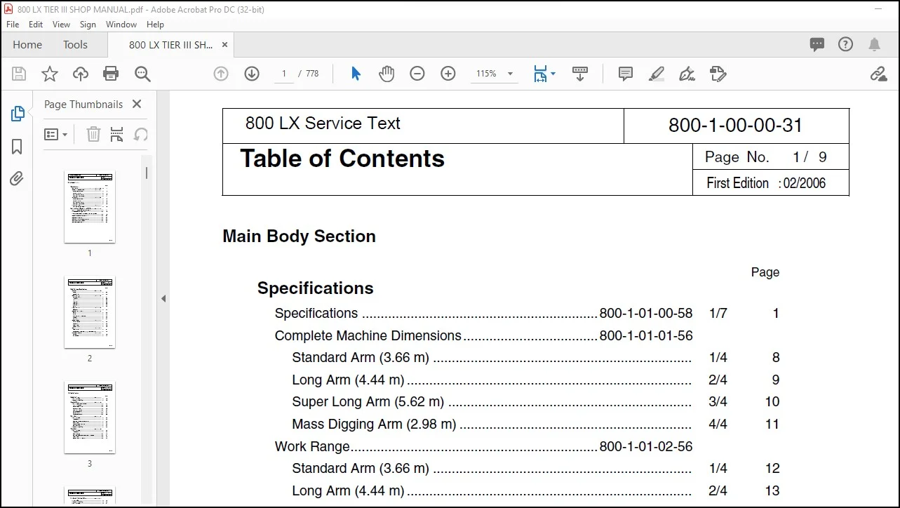
Specifications
Specifications 800-1-01-00-58 1/7 1
Complete Machine Dimensions 800-1-01-01-56
Standard Arm (3 66 m) 1/4 8
Long Arm (4 44 m) 2/4 9
Super Long Arm (5 62 m) 3/4 10
Mass Digging Arm (2 98 m) 4/4 11
Work Range 800-1-01-02-56
Standard Arm (3 66 m) 1/4 12
Long Arm (4 44 m) 2/4 13
Super Long Arm (5 62 m) 3/4 14
Mass Digging Arm (2 98 m) 4/4 15
Optional Components 800-1-01-03-28
List of Optional Components 1/1 16
Emission Control Regulation of 3rd-Stage 700-1-01-06-03
Execution Time Emission Control Regulation 1/12 17
Standard Amount of Exhaust Gas 2/12 18
Measures to be Taken for The Emission Control Regulation
3/12 19
Engine fuel and maintenance of fuel filters 4/12 20
Engine system Diagram 7/12 23
Construction of Engine (ISUZU 6WGIT) 8/12 24
Common Rail Injection System 9/12 25
Suction and Exhaust System 11/12 27
Page No 1
800 LX Service Text
SH800
800-1-00-00-31
Table of Contents / 9
First Edition :02/2006
Page
Major Equiment Specifications
Equipment 700-2-01-00-15
Overall 1/2 29
Operator’s Cab 2/2 30
Lower Mechanism 800-2-01-01-48
Assembly Drawing 1/3 31
Travel Unit 2/3 32
Take-up Roller 2/3 32
Upper-Roller 2/3 32
Lower Roller 2/3 32
Recoil Spring 3/3 33
Shoes 3/3 33
Upper Mechanism 800-2-01-02-45
Swing Unit 1/1 34
Engine and Related Areas 800-2-01-03-47
Engine 1/3 35
Muffler 2/3 36
Air Cleaner (With pre cleaner) 2/3 36
Radiator 2/3 36
Fuel Tank 3/3 37
Hydraulic System 800-2-01-04-48
Hydraulic Pump 1/3 38
Sump Tank 2/3 39
Rotating Joint 3/3 40
Solenoid Valve 3/3 40
Controls 800-2-01-05-49
Control Valve 1/2 41
Remote Control Valve (Left / Right, Travel operations) 2/2 42
Backhoe Attachments 800-2-01-06-50
Cylinder 1/2 43
Attachments 2/2 44
Page No 2
SH800
800-1-00-00-31
Table of Contents / 9
First Edition :02/2006
Hydraulic Section
Page
Hydraulic Pump 700-1-02-01-18
Operation Principle 1/2 45
Internal Structure Drawing 2/2 46
Contorol Valve 700-1-02-02-15
Operation Explanation of Each Part 1/16 47
1 Main Relief Valve 2/16 48
2 Overload Relief Valve 4/16 50
3 Foot Relief Valve 7/16 53
4 Load Holding Valve 8/16 54
5 Arm Regenerative 11/16 57
6 Priority Valve 14/16 60
7 Boom Regenerative 16/16 62
Swing Unit 700-1-02-03-12
Operation Principle 1/6 63
1 Hydraulic Motor 1/6 63
2 Anti-cavitation Check Valve Section 1/6 63
3 Relief Valve 2/6 64
4 Reversal Prevention Valve 4/6 66
5 Brake Section 5/6 67
Internal Structure Drawing 6/6 68
Travel Unit 700-1-02-04-15
Operation Principle 1/10 69
1 Hydraulic Motor 1/10 69
2 Parking Brake 2/10 70
3 2-Speed Switch Mechanism Oparation Principle 3/10 71
4 Relief Valve 8/10 76
5 Double Counterbalance Value 9/10 77
Page No 3
SH800
800-1-00-00-31
Table of Contents / 9
First Edition :02/2006
Fan Motor for Hydraulic Drive 700-1-02-05-02
Outside Drawing 1/7 79
Internal Structure Drawing 2/7 80
Operation Principle 3/7 81
1 Hydraulic Motor 3/7 81
2 Suction Safety Valve 4/7 82
3 Variable Flow Control Valve 6/7 84
4 Operation of Forward / Reverse Changeover Valve 7/7 85
Page No 4
SH800
800-1-00-00-31
Table of Contents / 9
First Edition :02/2006
Hydraulic Circuits Section
Page
Port Locations 700-1-03-00-23
Hydraulic Pump 1/2 86
Control Valve 2/2 87
Pilot Hose Connection Diagrams 800-1-03-01-28
Pilot P&T Lines 1/4 88
Pilot Control Lines 3/4 90
Functional Explanation 800-1-03-02-25
Functional Table 1/2 92
Travel Circuits 800-1-03-03-22
High Speed Travel Circuit 1/6 94
Low Speed Travel Circuit 3/6 96
Straight Travel Circuit 5/6 98
Swing Circuits 800-1-03-04-23
Swing Parking Circuit (Lever in Neutral / Swing Locked) 1/6 100
Swing Parking Circuit (Brake Released) 3/6 102
Swing Push Digging 5/6 104
Arm Circuits 800-1-03-06-22
Arm-Out Circuit 1/6 106
Arm-In Load Holding 3/6 108
Arm-In Circuit 5/6 110
Boom Circuits 800-1-03-07-22
Boom-Up Circuit (Single) 1/8 112
Boom-Up Circuit (Combined) 3/8 114
Boom-Down Load Holding 5/8 116
Boom-Down Circuit 7/8 118
Backup Circuits 800-1-03-09-21
Combined Circuit (Breaker Circuit) 1/4 120
Combined Circuit (High Speed Confluence Circuit) 3/4 122
Other Circuits 800-1-03-13-04
High Dump 1/2 124
Circuit Diagrams (Located inside the poket at back of back cover)
Hydraulic Circuit Diagram (A1)
Page No 5
SH800
800-1-00-00-31
Table of Contents / 9
First Edition :02/2006
Electric Circuits Section
Page
Operation Explanation 800-1-04-01-26
System Chart of Functons 1/56 126
Engine Control 5/56 130
Work Mode Selection 12/56 137
a)H S L Modes 14/56 139
b)Auto Modes 14/56 139
c)Load Prefetch Control 17/56 142
Throttle Control 18/56 143
Idling Control (Auto/One-touch) 21/56 146
Breaker Mode 23/56 148
Auto Preheat (Glow Control) 24/56 149
Auto Warm-up 27/56 152
Overheat Protection 28/56 153
Atmospheric Pressure Compensation 29/56 154
Control When Starting Engine 30/56 155
Control When Stopping Engine 31/56 156
Emergency Stop of the Engine 31/56 156
Engine Protection Function (EPF) 32/56 157
Lever Lock 34/56 159
Auto Boost Control 35/56 160
Swing Lock 36/56 161
Swing Brake Control 36/56 161
Travel Speed Switch-over 38/56 163
Travel Alarm 39/56 164
Power Shut-off Delay 40/56 165
Control Of Hydraulic Driven Fan 41/56 166
Fuel Supply Pump Control (Automatic stop) Option 50/56 175
Power Transistor Protection 52/56 177
Monitor Display 53/56 178
a)Nomal Display 53/56 178
b)Message Display 56/56 181
Page No 6
SH800
800-1-00-00-31
Table of Contents / 9
First Edition :02/2006
Page
Service Support 800-1-04-04-08
Summary 1/20 182
Operating Insttructions 1/20 182
Measuring Electrical Device 800-1-04-02-17
Instruments to be Measured 1/10 202
Equipment for Measuring 1/10 202
Measuring Methods 6/10 207
Initial Controller Settings 700-1-04-05-07
Verifying the Settings 1/3 212
Resetting Procedures 1/3 212
Setting Procedures 1/3 212
List of Settings 2/3 213
Error Display Functions 3/3 214
Troubleshooting 700-1-04-06-11
Problem Symptoms 1/12 215
Inspections Prior to Troubleshooting 2/12 216
Troubleshooting Procedures 3/12 217
Using the Flow Chart 4/12 218
Diagnosis 5/12 219
(1) Refilling Fuel 5/12 219
(2) Refilling Coolant 6/12 220
(3) Low Engine Oil Pressure 7/12 221
(4) Overheat 8/12 222
(5) Battery Charging 10/12 224
(6) Faulty Electrical System 11/12 225
Electric Wiring Diagrams 800-1-04-07-23
Electrical Components and Wiring (Frame) 1/2 227
Electrical Components and Wiring (Cab) 2/2 228
Harness Diagrams 800-1-04-08-23
Frame Main Harness 1/2 229
Cab Main Harness 2/2 230
Circuit Diagrams (Located inside the poket at back of back cover)
Electric Circuits Diagram (A1)
Page No 7
SH800
800-1-00-00-31
Table of Contents / 9
First Edition :02/2006
Maintenance Section
Page
New Machine Performance
Performance Evaluation Check Sheet 000-3-02-00-15 1/2 231
Reference Values 800-3-02-01-25 1/1 233
Instructions For Measuring And Adjusting Pressure
800-1-05-00-28
Measuring Pressure 1/14 234
1 Basic Conditions 1/14 234
2 Set Values 1/14 234
3 Pressure Measuring port 2/14 235
4 Preparation for Measuring Pressure 4/14 237
5 Measuring Pressure 6/14 239
6 Measuring Other Pressures 8/14 241
Adjusting Pressure 9/14 242
1 Pressure Adjusting Points 9/14 242
2 Instructions for Adjusting Pressure 11/14 244
Maintenance Of The Circumference Of Engine
700-1-05-07-03
1 Circumference Filter Arrangement of Engine 1/3 248
2 Fuel Element System Diagram 2/3 249
Main Body Weight 800-3-01-00-49
1 Major Component Weight 1/2 251
2 Individual Part Weight 2/2 252
3 Shoe Weight 2/2 252
4 Arm Weight 2/2 252
Attachments Dimensions 800-1-05-04-22 1/1 253
Compatibility 800-1-05-05-26 1/1 254
Plastic Shim 000-1-05-08-02 1/1 255
Procedures For Changing Operation Type 000-8-02-01-07
1 ISO Type 1/4 256
2 Old SumitomoType 2/4 257
3 Old Mitsubishi Type 3/4 258
4 Old Kobelco Type 4/4 259
Page No 8
SH800
800-1-00-00-31
Table of Contents / 9
First Edition :02/2006
Assembly, Disasembly Section
Page
Summary of Assembling 800-0-06-00-05
Total Work Process 1/36 260
Major Machines ・ Tools ・ Equipment Table 2/36 261
Matters to be Attended 5/36 264
Prior Preparation 5/36 264
Prior Preparation Procedure 7/36 266
Unloading Work 8/36 267
Connection of Lower Sideframes to Upper Swing Body 14/36 273
Mounting Travel Motor Lines 20/36 279
Mounting Counterweight 22/36 281
Mounting Attachments 24/36 283
Checking Work 34/36 293
Confirmation of Movement After Assembling Work 35/36 294
Summary of Disassembling 800-1-06-01-05 1/5 296
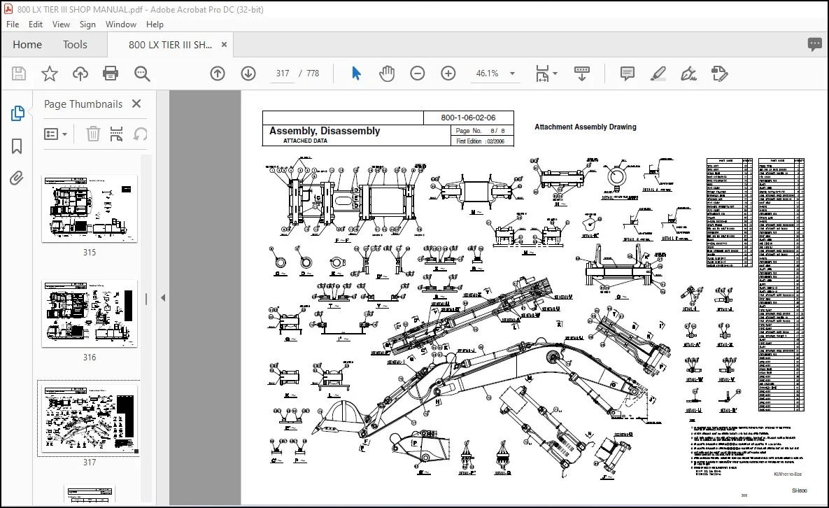
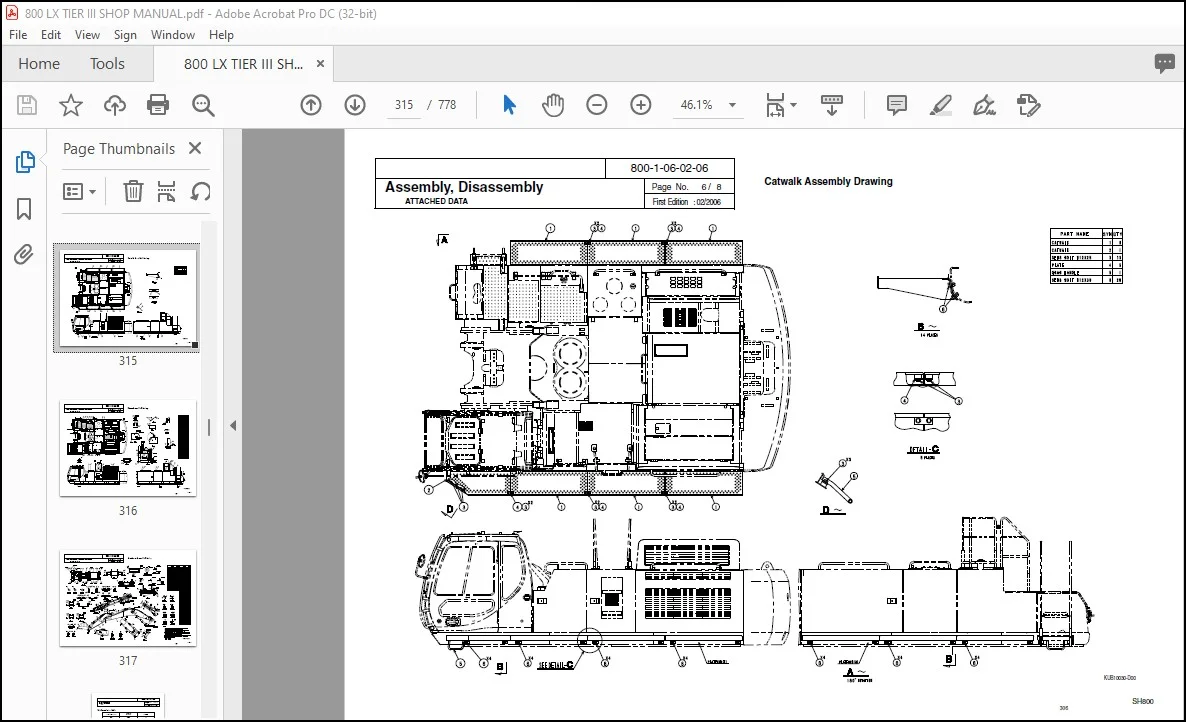
Attached Data 800-1-06-02-06 1/8 301
Appendix
Unit Conversion Table 300-1-08-01-02 1/1 309
New Hydraulic Oil 300-1-08-02-02 1/1 310
Questions? Email us: [email protected]
https://vimeo.com/769358597
PLEASE NOTE:
- This is the SAME exact manual used by your dealers to fix your vehicle.
- The same can be yours in the next 2-3 mins as you will be directed to the download page immediately after paying for the manual.
- Any queries / doubts regarding your purchase, please feel free to contact [email protected]
S.V