Linkbelt D16 Articuled Truck Shop Manual 1008 – PDF DOWNLOAD
Original price was: $86.95.$27.95Current price is: $27.95.
Linkbelt D16 Articuled Truck Shop Manual 1008 – PDF DOWNLOAD
Description
Linkbelt D16 Articuled Truck Shop Manual 1008 – PDF DOWNLOAD
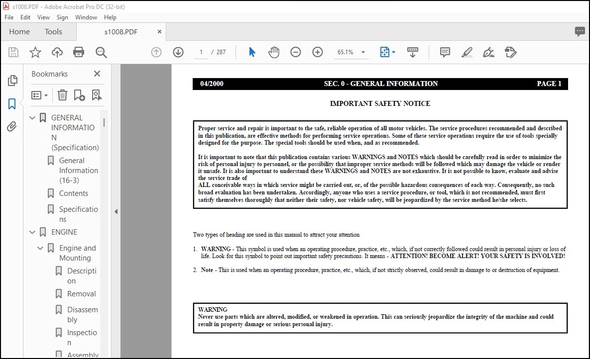
FILE DETAILS:
Linkbelt D16 Articuled Truck Shop Manual 1008 – PDF DOWNLOAD
Language : English
Pages : 287
Downloadable : Yes
File Type : PDF
Size: 2.88 MB
IMAGES PREVIEW OF THE MANUAL:
DESCRIPTION:
Linkbelt D16 Articuled Truck Shop Manual 1008 – PDF DOWNLOAD
INTRODUCTION:
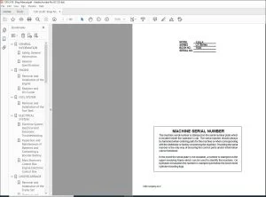
- This Workshop Manual is presented in 8 Primary Sections plus this Introduction. Each Section is then sub-divided according to the index shown at the beginning of each Section.
- The material in this document is for information only and is subject to change without prior notice. While reasonable efforts have been made in the preparation of this document to assure its accuracy, the company assumes no liability resulting from errors or omissions in this document, or from the use of the information contained herein.
- The company reserves the right to make changes in the product design without reservation and without notifications to its users.
TABLE OF CONTENTS:
Linkbelt D16 Articuled Truck Shop Manual 1008 – PDF DOWNLOAD
GENERAL INFORMATION (Specification) 1
General Information (16-3) 5
Contents 7
Specifications 9
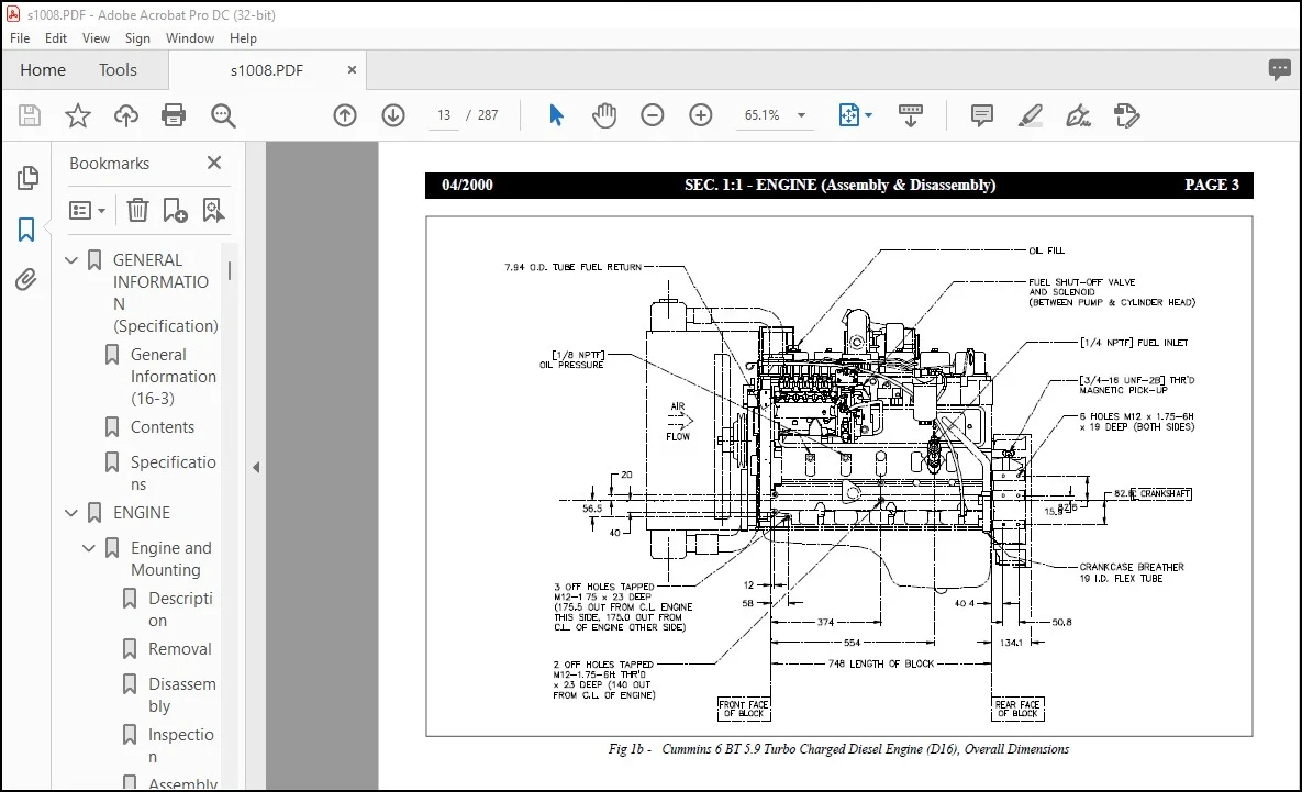
ENGINE 11
Engine and Mounting 11
Description 17
Removal 17
Disassembly 18
Inspection 18
Assembly 19
Installation 19
Maintenance 20
Oil Level Check 20
Induction System 21
Description And Operation 22
Maintenance 22
Exploded view of a Air Cleaner 23
Disassembly 24
Cleaning Methods 24
Air Cleaner Assembly 25
Recommendations 26
Cooling System 27
Description 28
Operation 28
Preventive Maintenance 28
Cleaning The Cooling System 29
Recommended Coolants 30
Antifreeze Table (Gal/Fahrenheit) 31
Antifreeze Table (Liters/Celsius) 34
Diagnosis Chart 34
Radiator and Mounting 35
Removal 36
Exploded view of Radiator Assembly 37
Disassembly 38
Inspection 38
Assembly 38
Installation 39
Cleaning 39
Servicing – Special Torque Specifications 40
Coolant Fill Instructions 41
Transmission Oil Cooler 43
Removal 44
Cleaning and Disassembly 45
Assembly 46
Installation 46
Service Tools 46
Hydraulic Oil Cooler 47
Description and Operation 48
Removal 48
Cleaning and Inspection 48
Installation 49
Maintenance 49
AXLES, WHEELS TIRES 51
Drive Lines 51
Description 54
Removal 54
Disassembly 54
Inspection 55
Assembly 56
Installation 57
Maintenance 58
Slip Joints 58
Periodic Inspection 58
Service Tools 58
Special Toque Specifications 59
Diagnosis Chart 59
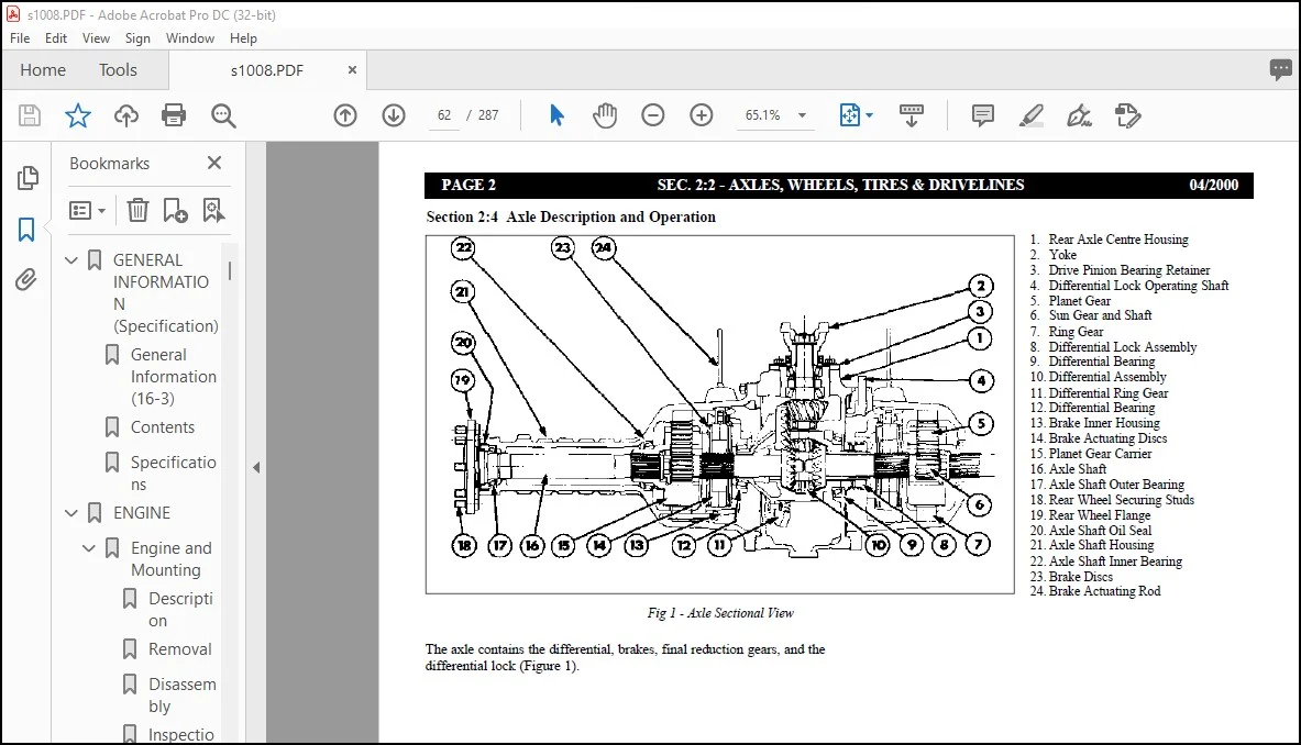
Front and Rear Axle & Differentials 61
Torque Transfer 63
Differential Lock Operation 63
Differential Lock Assembly 64
Brake Operation 65
Disassembly 74
Inspection and Repair 74
Assembly 75
Disassembly 76
Wheel, Rim & Tires 88
Description and Operation 89
Preparation For Servicing 89
Removing Tire & Rim Assembly From Machine 89
Dismounting Tire From Rim 90
Inspection 91
Mounting Tire On Rim 92
Mounting Tire & Rim Assembly On Machine 93
Tire Inflation 93
Tire And Wheel Rim Maintenance 94
Tire Care 95
Maintenance 96
Tubeless Tire Leak Diagnosis 97
Tire Inflation Pressures – General 98
Special Torque Specifications 98
Inflation Procedure 100
Special Tool 102
Special Torque Specifications 102
TRANSMISSION & MOUNTING 104
Transmission & Mounting 104
Description 106
Removal 106
Disassembly 106
Inspection 107
Assembly 107
Installation 108
Maintenance 109
FORE BODY & CAB 110
Front Suspension 110
Description 111
Removal 111
Disassembly 112
Assembly 112
Installation 112
Hydraulic Tank 114
Description 115
Removal 115
Installation 116
Exploded view of the Diffuser Assembly 117
Fuel Tank 118
Description 119
Operation 119
Removal 119
Installation 120
Maintenance 120
Exploded view of Filler Cap 121
Front Suspension Charging 122
Suspension Cylinders Charging Procedure 122
Articulation Oscillation Pivot 124
Removal 125
Assembly 126
Inspection 127
Maintenance 127
Bonnets & Cowls 128
Removal 129
Installation 129
Maintenance 129
Wheel Arches 130
Removal 131
Installation 131
Maintenance 131
Cab & Mounting 132
Description 133
Removal 133
Assembly of Cab Fig 1b 134
Assembly of Cab Fig 1c 135
Cab Fixing Positions Fig 2 136
Installation 137
Battery Box and Mounting 138
Removal 139
Charging The Battery 139
Installation 139
Heater/Air Conditioning 140
Exploded View, Internal Section of Heater/Air Conditioner Combined Unit 140
Description 144
Maintenance 144
Grammar & Auxiliary Cab Seats 146
Exploded View of Grammar Cab Seat Mounting Bracket 147
Exploded View of Auxiliary Seat Adjustment 149
REAR BODY 150
Rear Body & Mounting 150
Description 151
Removal 151
Assembly of Rear Body Pivot Pins Fig 2 152
Installation 153
Body Shimming Procedure 153
Maintenance 154
Tip Body Cylinder 156
Description 157
Removal 157
Disassembly 157
Inspection 158
Assembly 158
Installation 159
Maintenance 160
Rear Axle Suspension 162
Description 163
Removal 163
Disassembly 164
Assembly 164
Installation 164
Assembly of Suspension Cylinder Fig 2 165
HYDRAULIC PLANT 166
Hydraulic Pressure Adjustment 166
Description 167
Hydraulic Circuit 6:1a 169
Main Hydraulic Pump 172
Removal 173
Maintenance 173
Pilot Operated Spool Valve 174
Removal 175
Assembly 175
Steering System 176
Description 177
Filling And Bleeding The Steering System 178
Maintenance 178
Pressure Filter 6:4a 180
Description 181
Operation 181
Maintenance 181
Special Torque Specifications 182
Steering Valve 6:4b 184
Exploded View of Steering Valve 185
Description 186
Operation 186
Removal 187
Disassembly 188
Exploded View of Steering Valve 189
Inspection 190
Assembly 191
Installation 194
Filling And Bleeding The Steering System 196
Special Torque Specifications 197
Condition, Reason, Remedy 198
Steering Cylinder 6:4c 200
Description 201
Operation 201
Removal 201
Disassembly 202
Inspection 202
Assembly 203
Installation 203
Maintenance 204
Special Tools – Special Torque Specifications 204
Service Brake 206
Removal 207
Assembly 207
Park Brake Valve 208
Removal 209
Maintenance 209
ELECTRICAL PLANT 210
Circuit Diagrams 210
D16 14 Pole Link Over 211
D16 Steering Column (32) 212
D16 Steering Column (48) 213
D16 Cab Roof Harness 214
D16 New ZF Cab Harness (Time) 215
D16 Schematic of Main Harness 216
D16 Main Harness 217
Schematic Heater – AC System 221
Alternator 222
Removal 223
Installation 223
Starter Motor 224
Removal 225
Installation 225
Electrical Sensors & Switches 226
Description 227
Internal View of D16 Cab Fig 3 229
Digital Display 231
Lighting 234
Front Head Lights 235
Rear Brake/Indicator/Tail Light 235
Side Marker Lights 237
Front Work Lights 237
View of Side Marker Light Fig 3 238
Assembly of Front Work Light and Fixings Fig 4 239
Reversing Light and Fog Light Assemblies Fig 5 240
Removal 241
Installation 241
Rear Light Cable run Hose Assembly 242
Reversing Alarm and Junction Box 243
CCTV 244
Reversing Camera Installation 245
Description 246
Removal 246
Monitor 246
Installation 247
Maintenance 250
Fault Finding 250
Circuit Diagram for CCTV System 251
Item, Description, Specification 252
Radio/Cassette Player 24V(RM9624) 254
Wiring Diagram (RM9624) 255
Description 256
Removal 256
Installation 256
Maintenance 257
Blocking Diode (RM9624) 258
Installation 258
Specifications 259
Speakers 260
Wiring Diagram 261
Description 262
Removal 262
Installation 262
Specifications 263
MISCELLANEOUS 264
Lubrication System 264
Daily/Weekly 265
Monthly/3 Monthly 266
6 Monthly/Annually 267
Lubrication And Miscellaneous Servicing 268
Lubrication and Service Chart 268
Miscellaneous Servicing Information 270
Every 10 Hours of Operation (Daily) 270
After First 100 Hours of Operating New or Rebuilt Components 271
Every 250 Hours of Operation (Monthly) 271
Every 1000 Hours of Operation (6 Months) 272
Every 2250 Hours of Operation (Annually) 272
Engines and Transmissions 272
Recommended Lubricants 273
Lubricant Grade Selection Guide at Ambient (Start Up) Temperature 274
Notes on Recommended Lubricants and Lubricant Grade Selection Tables 275
Axle Bolt & Nut Torque Specifications 276
Torque Limits in Nm (Ibf ft) 276
Metric ISO Thread DIN 13 276
Special Torque Specifications 279
Standard Bolt & Nut Torque Specifications 280
Recommended Maximum Torques (Imperial) +/- 1-% 281
Unit Storage 284
General 284
Temporary Storage 284
Extended Storage – Under Sic Months 284
Extended Storage – Over Six Months 285
Removal From Extended Storage 285
Questions? Email us: [email protected]
PLEASE NOTE:
- This is the SAME MANUAL used by the dealerships to diagnose your vehicle
- No waiting for couriers / posts as this is a PDF manual and you can download it within 2 minutes time once you make the payment.
- Your payment is all safe and the delivery of the manual is INSTANT – You will be taken to the DOWNLOAD PAGE.
- So have no hesitations whatsoever and write to us about any queries you may have : heydownloadss @gmail.com
S.V