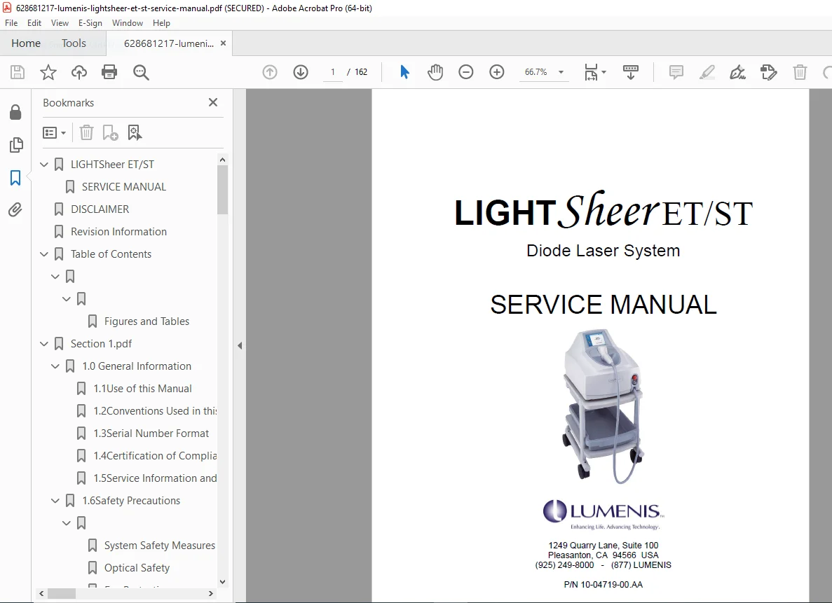
Lumenis LightSheer ET ST Diode Laser Service Manual PDF Hair Removal System – PDF
Original price was: $65.00.$18.95Current price is: $18.95.
Complete 162-page technical service manual for Lumenis LightSheer ET/ST 800nm diode laser hair removal systems. Comprehensive guide covering installation, calibration, troubleshooting, theory of operation, circuit schematics, parts lists, and repair procedures for biomedical technicians servicing these Class IV medical aesthetic laser devices.
Description
Lumenis LightSheer ET ST Diode Laser Service Manual PDF Hair Removal System – PDF DOWNLOAD
DESCRIPTION:
This comprehensive Lumenis LightSheer ET/ST Technical Service Manual provides complete technical documentation for servicing and maintaining LightSheer diode laser hair removal systems manufactured by Lumenis, Inc. This 162-page professional manual is essential for certified biomedical equipment technicians, laser service engineers, and authorized service personnel working on these advanced Class IV medical aesthetic laser systems.
Models Covered
This technical service manual covers both variants of the LightSheer diode laser platform:
LightSheer ST (Standard Model)
- Maximum pulse energy fluence: 10-40 J/cm²
- Repetition rate: ≤1 Hz
- Standard configuration for hair removal treatments
- Optimized for general aesthetic practice use
LightSheer ET (Enhanced Model)
- Maximum pulse energy fluence: 10-60 J/cm²
- Repetition rate: ≤2 Hz
- Enhanced power delivery for faster treatments
- Higher fluence capability for difficult hair types
Both systems feature AlGaAs (Aluminum Gallium Arsenide) laser diode array technology at 800nm wavelength with integrated ChillTip™ cooling for enhanced patient comfort and treatment efficacy.
Complete Manual Contents
Section 1.0: General Information
- Use of This Manual – Navigation guide and manual organization
- Conventions Used – Symbol definitions and safety notation system
- Serial Number Format – System identification and tracking
- Certification Compliance and Approvals:
- US FDA Class II Medical Device classification
- CDRH Class IV Laser designation
- Medical Device Directive (MDD) 93/42/EEC compliance
- EN 60825-1 Class 4 laser classification
- IEC 60601-1 medical electrical equipment safety
- IEC 60601-1-2 electromagnetic compatibility (EMC)
- IEC 60601-1-4 programmable electrical medical systems
- RWTÜV certification
- Service Information and FDA Compliance:
- Required warning logotypes reproduction
- Service procedure safety requirements
- Maintenance schedule compliance
- Radiation exposure control identification
- Removable protective housing documentation
- Safety Precautions:
- Class IV laser safety protocols
- Eye and skin protection requirements
- Protective eyewear specifications (OD ≥5 @ 790-830nm)
- Invisible radiation hazards (infrared wavelength)
- Nominal Ocular Hazard Distance (NOHD): 50m (164 ft)
- Emergency stop procedures
- Key switch and interlock systems
- System Specifications (Complete Tables):
- Laser specifications:
- AlGaAs laser diode array technology
- Wavelength: 800nm nominal (790-830nm range)
- Maximum peak power: 1600W (average during pulse)
- Pulse width: 5-100ms adjustable
- Spot size: 9mm x 9mm (81mm²)
- Beam divergence: 20° x 20° nominal
- Electrical power:
- Universal auto-ranging: 100-240 VAC
- Single phase with earth ground
- Maximum current: 12A
- Frequency: 50/60 Hz
- Physical characteristics:
- Dimensions: 43cm W x 51cm D x 38cm H (17″ x 21″ x 15″)
- Weight: 27 kg (60 lbs)
- Environmental requirements:
- Operating temperature: 15-27°C (60-80°F)
- Operating humidity: 0-70% @ 27°C non-condensing
- Operating pressure: 90-110 kPa
- Storage temperature: -10°C to 55°C
- External connections:
- Power cord: 2.4m (8 ft)
- Foot pedal hose: 1.8m (6 ft)
- Handpiece umbilical: 1.8m (6 ft) operating radius
- Cooling requirements:
- Forced air convection
- Minimum 15cm (6″) clearance all sides
- Laser specifications:
Section 2.0: Installation and Operation Information
- Introduction – Installation overview and requirements
- Inspection Procedures – Receiving inspection checklist
- Unpack System – Proper unpacking sequence and precautions
- Assembly Procedure:
- Component identification
- Connection procedures
- Initial setup steps
- Umbilical cord routing
- System Operation:
- Power-up sequences
- Touch screen interface navigation
- Treatment parameter selection
- Footswitch operation
- ChillTip™ cooling activation
- Remote Interlock Switch Installation:
- Wiring diagram and specifications
- Installation procedures
- Testing and verification
- Operational and Safety Checkout (Service Technician):
- Complete functional testing protocol
- Safety interlock verification
- Emergency stop testing
- Laser output verification
- Cooling system performance
- Periodic Maintenance:
- Scheduled maintenance intervals
- Inspection checklists
- Cleaning procedures
- Component replacement schedules
- Return Shipping:
- Proper packaging procedures
- Shipping preparation
- Documentation requirements
Section 3.0: Alignment, Adjustment and Calibration
- Overview – Calibration philosophy and requirements
- Touch Screen Calibration:
- Screen alignment procedures
- Touch sensitivity adjustment
- Verification testing
- ADC Loop Calibration:
- Analog-to-Digital Converter setup
- Signal calibration procedures
- Verification measurements
- Main Heat Exchanger Temperature Calibration:
- Temperature sensor calibration
- Setpoint adjustment
- Accuracy verification
- EPI (ChillTip™) Temperature Calibration:
- Contact cooling calibration
- Temperature control optimization
- Patient comfort settings verification
- Verify Heat Exchanger TE Coolers Current:
- Thermoelectric cooler testing
- Current measurement procedures
- Performance verification
- Verify EPI TE Coolers Current:
- ChillTip cooler current testing
- Operational range verification
- Thermal performance validation
- Calibrate Voltage Overcharge:
- Capacitor charging system calibration
- Voltage limit settings
- Protection circuit verification
- Verify Laser Current (Pump):
- Diode array current measurement
- Drive circuit verification
- Power output correlation
- Verify Pulse Width:
- Pulse duration accuracy testing
- Timing circuit calibration
- Oscilloscope measurement procedures
- Verify Array Over Temperature Bit:
- Thermal protection testing
- Sensor functionality verification
- Safety shutdown validation
- Output Energy Calibration:
- Energy meter setup and calibration
- Power meter measurements
- Calibration factor calculation
- Documentation procedures
Section 4.0: Theory of Operation
- Introduction – System architecture and design overview
- User Interface:
- Touch Sensitive Color Display Panel Assembly:
- LCD specifications and technology
- Touch screen controller
- Display driver circuits
- User interface software
- Footswitch (and Pneumatic Foot Pedal):
- Activation mechanism
- Safety interlock integration
- Signal processing
- Remote Interlock:
- External safety interlock functionality
- Wiring and connection specifications
- Fail-safe operation
- Key Switch:
- Access control mechanism
- Position sensing
- System enable logic
- Emergency Stop Switch:
- Immediate shutdown capability
- Redundant safety design
- Latch mechanism
- Touch Sensitive Color Display Panel Assembly:
- Handpiece Calibration Port:
- Pocket (Holster):
- Parking position detection
- Calibration sequence initiation
- Proximity Sensor:
- Optical sensing technology
- Handpiece position detection
- Wiring and signal processing
- Diffuser Glass:
- Optical properties
- Light distribution function
- Calibration reference
- Photodiode (Energy Detector):
- Silicon photodiode specifications
- Signal conditioning
- Energy measurement accuracy
- Pocket (Holster):
- Software Architecture:
- User Software Routines:
- START-UP:
- Initialization sequences
- Self-test procedures
- System diagnostics
- Error checking
- CALIBRATION:
- Energy meter calibration algorithm
- Automatic zero adjustment
- Reference measurements
- TREATMENT:
- Parameter control
- Safety monitoring
- Pulse delivery sequences
- Real-time feedback
- SLEEP MODE (Screen Saver, Power Saver):
- Energy conservation
- Quick wake-up
- Parameter retention
- INTERLOCK MODE:
- Safety lockout states
- Reactivation procedures
- Status indication
- FAULT STATE:
- Error detection and logging
- Recovery procedures
- Diagnostic information
- START-UP:
- Contents of Persistent Memory (NVRAM):
- Configuration data storage
- Calibration factors
- Treatment history
- User preferences
- User Software Screens:
- Screen navigation and zones
- Loading program screen
- Startup screen
- Warning and caution displays
- Service mode activation
- Paused screen
- Mode selection screen
- Setup screen interface
- Diagnostic screen access
- Service Software:
- Access to Service Software – Security and entry procedures
- Set-up Screen – Configuration parameters and adjustments
- Diagnostic Screen – Real-time system monitoring and testing
- Demo Software – Training and demonstration mode
- User Software Routines:
- Electrical Connection and Conditioning:
- Facility Electrical Outlet – Requirements and specifications
- Power Cord – Construction and ratings
- Power Input Module:
- EMI/RFI filtering
- Surge protection
- Universal voltage input
- Main Power Switch (Circuit Breaker):
- Current limiting protection
- Manual disconnect
- Safety compliance
- Power Supply and Laser Drive:
- Lambda Power Supply (legacy systems):
- High-current DC power generation
- Voltage regulation
- Protection circuits
- FET (Diode Current Control):
- Field Effect Transistor switching
- Current modulation
- Pulse shaping
- Connection diagrams
- Martek Power Supply (current systems):
- Switching power supply design
- Output specifications
- Control signals
- Block diagram analysis
- Lambda Power Supply (legacy systems):
- Control Electronics:
- CPU Controller Board:
- Motorola ColdFire® processor
- Memory architecture
- I/O interfaces
- Communication protocols
- Schematic diagram
- PWA Main Board:
- Signal processing
- Sensor interfaces
- Control outputs
- Power distribution
- Schematic diagram
- Energy Meter Board:
- Photodiode signal conditioning
- A/D conversion
- Energy calculation
- Calibration storage
- Component identification
- PWA Fan Speed Control Board:
- Temperature-based fan control
- Speed regulation
- Thermal management
- CPU Controller Board:
- Cooling System:
- Overview – Thermal management strategy
- Components:
- Heat exchanger assembly
- Thermoelectric (TE) coolers
- Fans and air circulation
- Temperature sensors
- Coolant circulation (if applicable)
- ChillTip™ contact cooling mechanism
- Cooling system diagram
- Delivery System:
- Overview – Optical path and beam delivery
- Components:
- Handpiece Optical System:
- Fiber optic coupling
- Collimating optics
- Focusing elements
- Beam homogenization
- Laser Diode Array Optical Detail:
- Array configuration
- Optical coupling efficiency
- Beam shaping optics
- Laser Diode Array Construction Detail:
- Bar array assembly
- Thermal management integration
- Electrical connections
- Protective coatings
- Handpiece assembly components
- Umbilical cord construction
- Handpiece Optical System:
Section 5.0: Troubleshooting
- Overview – Systematic troubleshooting methodology
- Interior Access and Part Location:
- Top Cover Removal:
- Fastener locations
- Removal sequence
- Safety precautions
- Component Location, Base Plate:
- Major component identification
- PCB locations
- Power supply positioning
- Connector access
- Component Location, Top Cover:
- Display panel assembly
- Control switches
- User interface components
- Component Location, Handpiece Assembly:
- Left side view components
- Right side view components
- Internal optics access
- Laser diode array location
- Top Cover Removal:
- Error Codes and Fault Isolation:
- Complete error code listing
- Error message interpretation
- Root cause analysis
- Diagnostic procedures for each fault
- Resolution steps
- Test Point and Connector Arrangement:
- PCB test point locations
- Voltage measurement points
- Signal monitoring locations
- Connector pinouts
- Signal lists for major assemblies
- Remove and Replace Procedures:
- Component-specific R&R procedures
- Required tools
- Calibration requirements after replacement
- Verification testing
Section 6.0: Selected Part Numbers
- Miscellaneous Parts / Quick List:
- Commonly replaced components
- Consumable items
- Fasteners and hardware
- Special Service Tools:
- Lumenis-specific tools
- Required test equipment
- Calibration instruments
- Safety equipment
- Top Cover Assembly:
- Display components
- Control switches
- Mounting hardware
- Base Plate Assembly:
- Structural components
- Major assemblies
- Fasteners
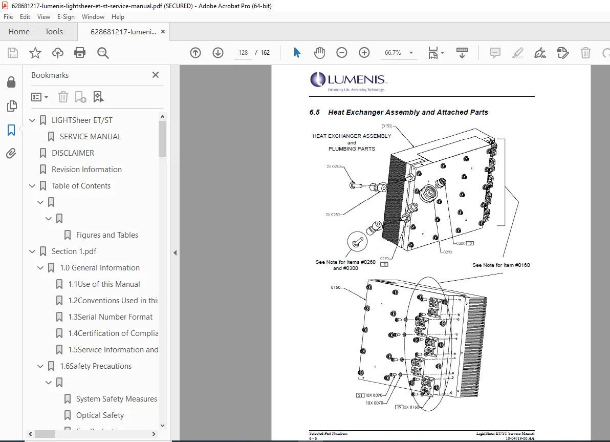
- Heat Exchanger Assembly and Attached Parts:
- Heat exchanger core
- TE coolers
- Temperature sensors
- Mounting brackets
- Pump Assembly:
- Cooling pump (if applicable)
- Tubing and fittings
- Electrical connections
- Cooling Fan Assembly:
- Fans and shrouds
- Filters
- Speed control components
- Handpiece Assembly:
- Handpiece shell
- Optics components
- ChillTip assembly
- Proximity sensor
- Umbilical cord
- Cable Harnesses:
- Internal wiring harnesses
- Connector assemblies
- Custom cables
Section 7.0: Technical Notes (TN) and Field Change Orders (FCO)
- Introduction – Purpose and use of TNs and FCOs
- Index of TN and FCO – Complete listing with descriptions
Section 8.0: Drawings and Schematics
- Index of Drawings and Schematics – Complete drawing list
- Simplified System Block Diagram – Overall system architecture
- System Wiring Diagram (Lambda Power Supply) – Complete system wiring for legacy systems
- System Wiring Diagram (Martek Power Supply) – Complete system wiring for current systems
- CPU Controller Board Schematic – Detailed electronic schematic
- PWA Main Board Schematic – Complete circuit diagram
- PWA FET Driver Board Schematic – Laser drive circuitry
- PWA Fan Filter Schematic – Cooling control circuits
- PWA Energy Meter Board Schematic – Energy detection circuitry
Comprehensive Figures and Tables:
- Over 40 detailed figures including:
- Safety label reproductions
- Wiring diagrams
- Component location photos
- Block diagrams
- User interface screenshots
- Optical system diagrams
- Mechanical assembly views
- Multiple specification tables
- Signal lists and pinouts
- Calibration forms
Key Features of This Service Manual
✓ Official Lumenis documentation – Authorized technical information ✓ 162 comprehensive pages with detailed procedures and diagrams ✓ Complete coverage of both ST and ET model variants ✓ Circuit-level schematics for all major assemblies ✓ Step-by-step calibration procedures for energy output accuracy ✓ Comprehensive troubleshooting with error code reference ✓ Safety compliance information per FDA and international standards ✓ Detailed theory of operation explaining all subsystems ✓ Parts identification with ordering information ✓ High-quality diagrams including optical system details ✓ Service software access procedures and functionality ✓ ChillTip™ cooling system complete technical documentation
Who Should Use This Manual
This Lumenis LightSheer technical service manual is designed for:
- Certified laser service engineers
- Biomedical equipment technicians with laser training
- Lumenis-certified service personnel
- Medical device repair facilities authorized for laser service
- Clinical engineering departments (with appropriate certification)
- Independent service organizations with laser certification
- Technicians who have completed Lumenis certification training
IMPORTANT: Per Lumenis disclaimer, this manual is specifically for use by formally trained service engineers and representatives who have passed Lumenis certification training. Servicing by uncertified personnel voids warranty.
Important Safety Information
The LightSheer ET/ST is a Class IV laser system requiring strict safety protocols:
- Invisible infrared radiation at 790-830nm wavelength
- Eye protection mandatory – OD ≥5 rated eyewear required
- Skin exposure hazards – Direct and scattered radiation dangers
- Nominal Ocular Hazard Distance – 50 meters (164 feet)
- Maximum pulse energy – 60 Joules
- Class II Medical Device – FDA regulated
- IIB classification – Medical Device Directive 93/42/EEC
System Capabilities
- Hair removal treatments – Permanent hair reduction for all skin types
- ChillTip™ contact cooling – Integrated epidermal protection
- Adjustable pulse width – 5-100ms for different hair types
- Variable fluence – 10-40 J/cm² (ST) or 10-60 J/cm² (ET)
- Large spot size – 9mm x 9mm for faster treatments
- Universal power – 100-240 VAC worldwide operation
Manual Quality and Format
- Format: Professional PDF document
- Security: Print-enabled for service use, copy-protected
- Pages: 162 pages of comprehensive technical content
- Graphics: High-resolution schematics, photographs, diagrams
- Organization: Logical section structure with complete table of contents
- File size: 11.7 MB – Detailed content with extensive graphics
- Optimization: PDF optimized for professional use
- Publisher: Lumenis, Inc. – Pleasanton, CA
This Lumenis LightSheer ET/ST Service Manual PDF provides complete technical documentation essential for professional service and maintenance of these advanced medical aesthetic laser systems used in dermatology practices, medical spas, and aesthetic clinics worldwide.
FILE DETAILS:
| Manual Type | Technical Service Manual |
|---|---|
| Models Covered | LightSheer ST (Standard)<br>LightSheer ET (Enhanced) |
| Device Type | Diode Laser Hair Removal System |
| Wavelength | 800nm (790-830nm range) |
| Year | 2003 Edition (Rev. AA) |
| Pages | 162 pages |
| PDF Quality | Excellent – Original manufacturer document |
| File Size | 11.7 MB |
| Language | English |
| Publisher | Lumenis, Inc. |
| Part Number | 10-04719-00.AA |
| Security | Print enabled, professional use |