M-4-SS ROTARY MANUAL BLAST HOLE DRILL MAINTENANCE & OPERATION – CAT ROTARY TRACK DRILLS – PDF DOWNLOAD
Original price was: $80.00.$34.95Current price is: $34.95.
M-4-SS ROTARY MANUAL BLAST HOLE DRILL MAINTENANCE & OPERATION – CAT ROTARY TRACK DRILLS – PDF DOWNLOAD
Description
M-4-SS ROTARY MANUAL BLAST HOLE DRILL MAINTENANCE & OPERATION – CAT ROTARY TRACK DRILLS – PDF DOWNLOAD
DESCRIPTION:
M-4-SS ROTARY MANUAL BLAST HOLE DRILL MAINTENANCE & OPERATION – CAT ROTARY TRACK DRILLS – PDF DOWNLOAD
INTRODUCTION
- The Marion Rotary Blast Hole Drill uses a tri-cone rock bit for the drilling of holes to accept an explosive material. The denotat on of the “charge” breaks the rock anri loosens the overburden.
- The rotary bit threads to drill pipe section that threads to a direct current electric motor on the rotary gearbox on t e mast. The rotary gearbox provides torque and rotary speed to the drill bit.
- A roller c ain hoist-pull down system, powered by two hydraulic motors, raises and lowers the rota y gearbox and provides a load (or force) to the drill bit. The drill air compressor uses a rotary vane impeller to supply air down thru the drill pipe and thru the drill bit. This baili111g air cools the bearings in the drill hit and removes the drilled material cuttings from the hole.
- A leveling system provided on the machine permits the operator to level the mac~ine hefore each drilling cycle. The leveling ic1cks (cylinders) are controlled in the operator’s cab with jack location front and rear at each 1 side of the machine.
- I The machine is equipped with an independent propel system which uses a hydraulic motor on each crawler. The operator is afforded control of each crawler separately to permit excellent machine maneuverability.
- The hoist-pull down and propel hydraulic circuits are included in the main hydr,.c . iic system. This system is powered by a 200 horsepower motor geared to two variao!e displacement axial piston pumps.
TABLE OF CONTENTS:
M-4-SS ROTARY MANUAL BLAST HOLE DRILL MAINTENANCE & OPERATION – CAT ROTARY TRACK DRILLS – PDF DOWNLOAD
Introduction
Operation (Gold) , Section 1
Machinery (Orange) Section 2
Hydraulic Systems (Copper) Section 3
Drill Air Components (Light Blue) Section 4
Auxiliary Air System and Components (Yellow) Section 5
Lubrication (Green) Section 6
Engineering Data (Maroon) Section 7
Electrical (Blue) Section 8
Maintenance Check List ( Red) Section 9
Automatic Drill Control Section 10
Auxiliary Generator Section 11
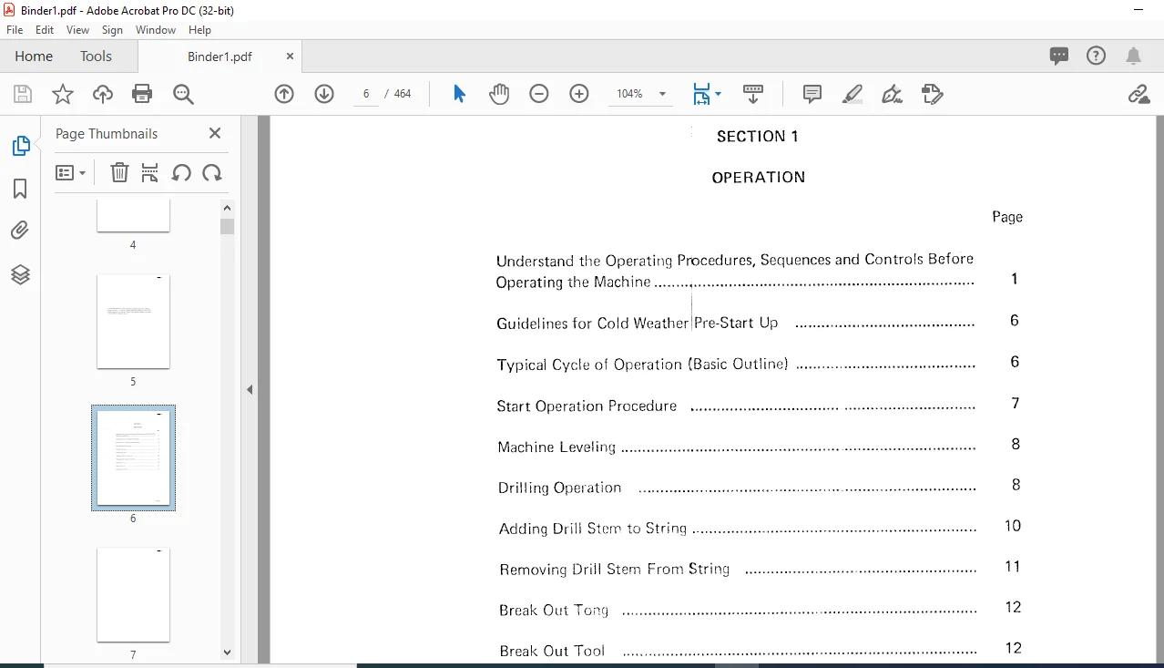
Understand the Operating Procedures, Sequences and Controls Before
Operating the Machine , 1
Guidelines for Cold WeatherlPre-Start Up 6
Typical Cycle of Operation (Basic Outline) 6
Start Operation Procedure 7
Machine Leve ling 8
Drilling Operation 8
Adding Drill Stery, to String 10
Removing Drill Stern From String 11
Break Out Tong 12
Break Out Tool 12
Indepcndent Propel 13\
Crawlers 1
Crawler Belt 1
Adjustment of Crawler Belt 2
Removing and Replacing Belts 3
Load Rollers and Top Rollers 3
Propel Gear Case , 4
Propel Brake
Leveling Jacks
Mast and Mast Machinery:
Maist Raising 8
Mast Lowering 8
Mast Braces 9
Hoist Pull Down Chain
Rotary Gearbox Aligninq Rollers
Hoist Pull Down Machinery 14
Hoist Pull Down Brakes
Stem Rack
Drill String
Angle Drilling Steady Guide
(Section 2 – Machinery cont ) Page
Break Out Tong 23
Break Out Tool (“Bit Pot”) 24
Winch and Lifting Tackle , 24
Machinery House , 26
House Ventilation System
Modular Concept r 1
Main Hydraulic System
Accumulator 2
Pressure Switches 2
Propel Mode 2
Mode Selection 2
Normal Hoist Pull Down 3
High Speed Hoist Pull Down Mode
Color Charts (4)
Propel Mode ( Re erse)
Propel Mode (#1 Pump in Neutral, #2 Pump Forward
Propel)(L H Crawler)
Hoist Pull Down Mode (Hoist – Normal Speed)
Hoist Pull Down Mode (Hoist – Fast Speed)
Hydrotransmission Valve
Installation 8
Acljust;ng _ 10
Recovery 25
Metal to Metal Contact 25
O-ring Problems 26
Poor Installation 26
lnc;tallation Prcpanation 28
Installation 29
Back Up Rings ~ 29
!
Basic Things to Rf member 31
Modes of Failure 32
Component Repair and Rep acemcnt:
Variable Dis[)laccment xial Piston Pump Assemblies 33
Main Pump Rep la emcnt 33
Main Pump I nstal at ion 34
Minor Repairs, V riablc Displacement Pump 35
Replacemen of Pump Shaft Seal 36
Replacement of harge Pump and Charge Check Valves 38
Removing Hydraulic Motor 46
Valve Assembly Removal and Disassembly 46
Crank Shaft Removal and Piston Assembly Break Down 46
Remove Bearings from Motor 47
Cylinder Head Removal 47
Crank Case Relief Valve Disasser-nbly
Component Inspection:
47
Valves, Pistons and Bores 4 7
Connecting Rod and Crankshaft 47
Bearing Inspection 48
Piston and Valve Seal Rings 48
0-rings 48
Shaft Seal 48
Retaining Rings 48
Socket Cap Screws 48
Oldham Coupling 48
Motor Assen)bly 49
BI006412
(Section 3 – Hydraulic Systems cont ) Page
Assembling Valve to Motor 49
Piston and Connecting Rod Assembling 50
Connecting Rod & Crank Case Reassembling into Motor Case 50
Setting Crank Shaft End Float 51
Cylinder Heat Refit 51
Cross Section of Staffa 52
Tyrone Pump:
Tyrone Pump Disassembly 54
Tyrone Pump Assembly
Sr aft Seal ReplacEjment
Parts Inspection
Leveling Jack Cylinder Se vice Instructions:
Piston Rod Assem ly 68
Head Seals and Bushing Replacement 68
Piston Seal Replacement 68
Piston Removal 69
Piston Re-Installation 69
Installation of Piston Rod Assembly into Cylinder 69
Jack Cylinder PcJrts Breakdown 70
Cross Section of Hydraulic Leveling Jack Cylinder 71
Troubleshooting the Hydraulic Systems:
Charge Pressure Low or Absent 72
Variable Displacement Pump Does Not Deliver Pressure
or Low Pressure 72
Hydraulic Motor Does Not Respond to C:ontrol 73
Pump Making Noise 73
Improper Operation of Motor 73
Low Auxiliary Hydraulic Pressure 73
Mast Wil! Not Lower 73
Stem Rack Will Not Lower 74
Machine Will Not Remain Level, Jack Will Not Hold 74
Excessive Heat in System 74
Troubleshooting Guide for Sundstrand:
Introduction 75
Instructions 75
Neutral Difficult or Impossible to Find 76
System Operating Hot 77
Transmission Operates in One Direction Only 78
System Response Sluggish 7’J
(Section 3 – Hydraulic Systems cont ) Page
System Will Not Operale in Either Direction 80
Inspect Control Valve 81
Inspect System Relief Valves 82
Inspect Shuttle Valve 82
Inspect Charge Check talves 83
Drill Air
Rotary Pressure Joint 2
Rotary Compressor 2
Cylinder 2
Precautions Before Starting 3
Starting Procedures 4
Operating Precautions 4
Intermittent Service Units
Blade Protection
Maintenance
Redoweling 10
Troubleshooting – Drill Air Compressor 12
Drill Air Compressor Lubricator 13
Operation of Lubricator (Manzel 94 V) 13
Troubleshooting ·- Force Feed Lubricator
Auxiliary Air Compressor · ·
Air Cleaner 1 1
Anti-Freezer
Anti-Freezer Adjustrnent 2
Oil Fog Lubricator 2
Filter Cleaning 2
Filter Pressure Regulator , 3
Air Valves t 3
Air Compressor Preventative Maintenance 4
Air Compressor Operation ·1 6
Pressure Switch 7
Check Valve : 8
Centrifugal Pressure Release CPR) 9
CPR Adjustment 9
CPR Servicing and Removal 9
I Safety Valves ; 10
Lubrication Fittings 1
Anti-Friction Bearings 1
Open Gears
Enclosed Gear Cases
Temperature Operation Range 1
Lubrication Specifications – Greases
Lubrication Specifications – Oils
GL – Gear ‘_ubricants (Oil Tf;pe)
Descrirition of Oil and Grease Classification
Special Lubrication Specifications for -50°C Celcius (-58°F)
Multi-purpose Grease (MPG)
HOF – Summer 14
HOF-Winter 14
Approved Products:
Full Approval 14
Conditional Approval 14
Final Acceptance 14
Fully Approved Products 14
Conditionally Approved Products 14
Special Hydraulic Drive Fluid (HDF) Specifications 15
Hydrostatic Drive Fluid (HDF) Maintenance 16
Lubrication of Crawler Mount 18
Lubrication of Rotary Gearbox and Pull Down 18
Lubrication of Stem Rack 19
Lubrication Miscellaneous 19
Semi-Automatic Lubrication for Drill 21
Replacement of Auto-Lube Components 21
Liquid Capacities of Machine (U S Gallons) 23
Uni-Block Lubemation System 24
Operation 26
Displacement and Porting Chart 27
Basic Lubemation Diagram 28 –
Bushing Replacement 1
Running Clearance for Bro ze Bushings 2
Installation of Oil and Grea e Seals 4
Split Seals 4
Gear Case Seal 5
Installation of Vee Ty e Grease Seals 6
Anaerobic Adhesives:
Surface Preparation – 6
Adhesive Removal 6
Adhesive Application 7
Cured Spline Disassem ly 7
Involute Spiine Assem lies Permanent Fit With Adhesive 7
Pressure Equipment 9
Finishing and Recommended Fits 10
Checking Coupling Alignment 10
The Solidly Coupled Sets Procedure 10
Recommended Torque Valves 11
Coup I ing Parts 13
Installation 14
Lubrication of Coupling During Assembly 16
Cap Screw Classes and Tightening Procedures 17
Turn-of-Nut rvlethod 17
Torque Method
Engineering Standard 1101-2
Welding Information:
Recommendations for Casting Repairs
Proper Preparation for Welding
Postheat 22
The Order of Welding 22
Peening 22
Reinforcing Requires xtreme Caution 23
Postheat Treatment 23
Material Identification – rion Material Symbol~ and Major
Component Parts:
Cast Iron Welding Ins ructions 24
Table 1 , 24
Electrodes 25
Preheats and Postheats 25
Material Reference Table f 26
of D C Motors and Generators
Brush Installation
Never Use Emery Cloth or Elmery Paper 2
Proper Lubrication 1 3
Feeder Cable 4
Power Line Grounding 4
General , 1
Daily I nspcction ( Electrical) ‘ 3
Daily Mechanical I nspcction ·” 5
Weekly Electrical Inspection 13
Weekly Mechanical I mpection 15
Monthly Electrical I nspcctior; , 25
Main Control Panel and Transducers
Systcrn Block DiatJrarn
Perforn1;cmce Assurance
Set-Up Procedures
Genera!
Preliminc1ry Measuromcnts
Power Supplies ,
Lo,1ic Coricl:tions
Manual Drill Set-Up
Servd 1\mp!ifier B<l!$nce Adjustment
Initial Conditions 3-4
Gain ,L\diustrrwnrs 3-5
Final Adjustments 3-5
Propel Set-Up 3-6
Local 3-6
Mother Board/Lovv Voltage Drop Out Assembly 4-1
Voita(le Reuulation 4-1
Povver A rnplifiers 4-4
Mother Board 7-1
Limit Control 7-1
Drill/Propel Logic 7-1
Propel Control 7-7
Joystick Option , 7-7
Meter Assembly 7-12
Service Kit 7-12
Maintenance 8-1
Preventive, Routine 8-1
A C Input Voltage Problems 8-1
Malfunction Flow Chart 8-2
Card Level Repair 8-2
Use of the Model 326 Meter Assembly 8-2
Factory Repairs 8-5
Spare Parts and Parts Lists 9-1
Recommended Spare Parts 9-1
Spare Parts Acquistion 9-1
Parts 9-1
Sub-Assembly Sheet 9-1
Control Panel Assembly , , 9-1
Main Chassis Assembly 9-1
P C Cards 9-1
Engineering Change Orders 11-1
ECO-255A-1 Capacitor Addition, 2/6/73 11-1
ECO-255A-2 Wiring Change, 2/6/73 11-2
ECO-255A-3 Component Change, 6/5/73 11-3
ECO-255A-4 P C Card (2151) Change, 11/11/75 11-4
Diesel Engine r– ·
Name and Explanation of E*h Part
Control Panel ~
Engine 1
AC Generator ,
Instruments Mounted in the Control Panel for AC Generator
Preparation ,,nd Inspection Before Starting the Engine
Starting Engine 7
Functions to Help Start Engine 8
Operation 8
Starting Engine Without Use of Preheating Device 9
Starting Engine With Preheat Device
Operation After the Engin8 Starts
Use of AC Power Source 11
Inspection During Operation 12
Stoppage , 13
Emergency Stop 13
Precautions on Hanuling 14
Battery 14
Maintenance Manual:
General Desicription 16
Anti-Vibration F~ub!Jer 1 16
Engine 16
Items c1nd l\11ethods f lmpection 16
Inspection 18
Troubles and Count rmcosures 26
Oil Supplv _,,+
Engine Main Part A justmcnt Dutel 38
M-4-SS
BI006412
(Section 11 – Auxiliary Generator cont ) Page
Generator Main Body
Contents and Method of Inspection 48
Method of Inspection 49
Main Causes 49
Countermeasures 49
Brush 50
Brush Holder and Stud
Bearing
Replacement of Bearing
General Description
AC Generator
Cont0 ol Panel
Mechanical Disorder
Standards for Adjustment
Items and Method of Inspection
Trouble in Battery
Overcharge
Maximum Current Charging
Insufficient Chc1rge
Volume of Electrolyte
Wrong I nstal I at ion
Blockade of Exhaust Portion 62
Freezing of Electrolyte Liquid 62
M-4-SS ROTARY MANUAL BLAST HOLE DRILL MAINTENANCE & OPERATION – CAT ROTARY TRACK DRILLS – PDF DOWNLOAD:
IMAGES PREVIEW OF THE MANUAL:


PLEASE NOTE:
- This is the SAME manual used by the dealers to troubleshoot any faults in your vehicle. This can be yours in 2 minutes after the payment is made.
- Contact us at [email protected] should you have any queries before your purchase or that you need any other service / repair / parts operators manual.
S.,M