Manitou 1440 1640 1840 EASI STB E3 Telehandlers Service Manual – PDF DOWNLOAD
Original price was: $86.95.$31.95Current price is: $31.95.
Manitou 1440 1640 1840 EASI STB E3 Telehandlers Service Manual – PDF DOWNLOAD
Description
Manitou 1440 1640 1840 EASI STB E3 Telehandlers Service Manual – PDF DOWNLOAD
FILE DETAILS:
Manitou 1440 1640 1840 EASI STB E3 Telehandlers Service Manual – PDF DOWNLOAD
Language : English
Pages : 608
Downloadable : Yes
File Type : PDF
Size: 90.4 MB
IMAGES PREVIEW OF THE MANUAL:
Need help? Contact: [email protected]
https://vimeo.com/780069528
DESCRIPTION:
Manitou 1440 1640 1840 EASI STB E3 Telehandlers Service Manual – PDF DOWNLOAD
PREAMBLE
This chapter deals with the general instructions and safety notice during inspection and maintenance
work.
Other instructions and warnings are indicated in each chapter concerned.
In order to reduce accident risks, make sure to:
–– Follow the instructions in the truck operating and maintenance manual.
⇒⇒ This manual should be found in all trucks.
–– Please follow all safety instructions.
–– Use the appropriate tools for any work to be performed.
–– Use original Manitou spare parts.
Any non-compliance increases the risk of accidents occurring which may lead to causing grievous bodily
harm and even death.
An efficient, dependable and profitable combination will be formed if the operator follows the safety
manual correctly and the machine is serviced properly.
TABLE OF CONTENTS:
Manitou 1440 1640 1840 EASI STB E3 Telehandlers Service Manual – PDF DOWNLOAD
TABLE OF CONTENTS 00…………………………………………. 1
GENERAL INSTRUCTIONS AND SAFETY NOTICE…………………………. 3
PREAMBLE………………………………………………… 4
MAINTENANCE POSITION……………………………………… 5
RULES FOR MAINTENANCE…………………………………….. 6
GENERAL CONTROL AND ADJUSTMENT………………………………… 9
STANDARD TIGHTENING TORQUES……………………………….. 10
TABLE OF CONTENTS 10…………………………………………. 11
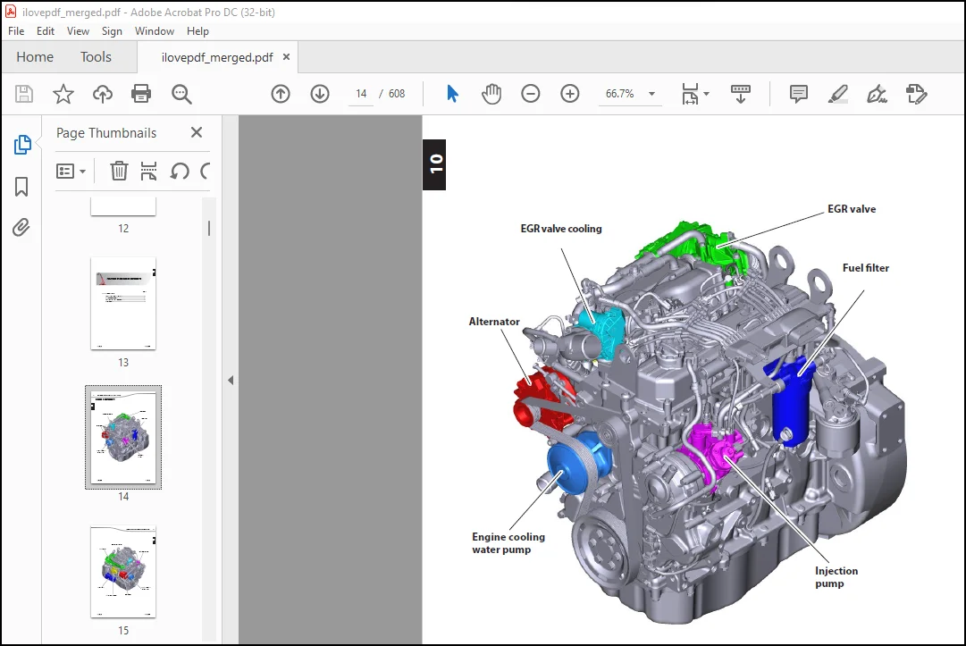
POSITION OF THE ENGINE COMPONENTS………………………….. 13
ENGINE COMPONENTS…………………………………….. 14
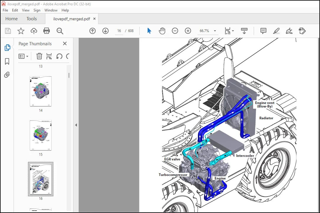
WATER + AIR COOLING CIRCUIT………………………… 16
INTAKE AND EXHAUST………………………………… 17
HYDRAULIC OIL COOLING CIRCUIT………………………. 18
FUEL CIRCUIT …………………………………….. 19
CHECKING AND ADJUSTING THE ENGINE………………………….. 21
POSITION OF THE COMPONENTS…………………………….. 22
PREPARATION AND SAFETY INSTRUCTIONS ………………… 22
A – REMOVING THE ALTERNATOR BELT……………………. 23
B – REMOVING THE ALTERNATOR………………………… 25
C – REMOVING THE STARTER MOTOR……………………… 26
D – REMOVING THE EGR VALVE…………………………. 27
E – REMOVING THE INJECTORS…………………………. 28
F – REMOVING THE ENGINE COOLING WATER PUMP…………… 29
ENGINE TIGHTENING TORQUE………………………………. 30
ASSEMBLING THE ENGINE……………………………… 30
REMOVING THE ENGINE………………………………………. 31
REINSERTING THE ENGINE……………………………………. 45
TABLE OF CONTENTS 20 ………………………………………… 57
FEATURES AND TECHNICAL SPECIFICATIONS OFTHE TRANSMISSION……… 59
TRANSMISSION LAYOUTS……………………………………… 73
POSITION OF THE TRANSMISSION COMPONENTS…………………….. 77
CHECKING AND ADJUSTING THE TRANSMISSION…………………….. 81
REMOVING THE TRANSMISSION…………………………………. 97
REINSERTING THE TRANSMISSION……………………………….103
SPECIAL TOOLS FOR THE TRANSMISSION………………………….109
TABLE OF CONTENTS 30 …………………………………………113
REMOVING THE AXLE…………………………………………115
REINSERTING THE AXLE………………………………………123
TABLE OF CONTENTS 40 …………………………………………131
FEATURES AND TECHNICAL SPECIFICATIONS OFTHE BRAKES……………….133
POSITION OF THE BRAKES COMPONENTS………………………………137
CHECKING AND ADJUSTING THE BRAKES………………………………139
SPECIAL TOOLS FOR THE BRAKES…………………………………..145
TABLE OF CONTENTS 50 …………………………………………147
BOOM CHARACTERISTICS AND SPECIFICATIONS……………………..149
BOOM COMPONENTS LOCATION…………………………………..153
BOOM CONTROL AND ADJUSTMENT………………………………..157
BOOM REMOVAL……………………………………………..171
BOOM REFIT……………………………………………….213
TABLE OF CONTENTS 70 …………………………………………261
HYDRAULIC SCHEMATIC DIAGRAMS……………………………….263
MRT 1440 – 1640 ST3B (400°)…………………………….265
MRT 1840 ST3B (400°)…………………………………..270
MRT 1840 ST3B (360°)…………………………………..276
HYDRAULIC COMPONENTS LOCATION………………………………283
HYDRAULIC CONTROL AND ADJUSTMENT……………………………289
HYDRAULIC COMPONENTS REMOVAL……………………………….311
REFITTING THE HYDRAULIC COMPONENTS………………………….327
HYDRAULIC SPECIFIC TOOLING…………………………………343
TABLE OF CONTENTS 80………………………………………….347
ELECTRICAL FEATURES AND SPECIFICATIONS………………………349
WIRING DIAGRAMS…………………………………………..465
MRT 1440 – 1640 – 1840 ST3B (400°) / MRT 1840 ST3B (360°)….469
POSITION OF THE ELECTRICAL COMPONENTS……………………….498
ELECTRICAL CONTROL AND ADJUSTMENT…………………………..511
SPECIAL TOOLS FOR THE ELECTRICAL SYSTEM……………………..567
TABLE OF CONTENTS 85 …………………………………………571
DRIVER’S CAB REMOVAL………………………………………573
DRIVER’S CAB REFIT………………………………………..581
TABLE OF CONTENTS 90 …………………………………………589
FRAME REMOVAL…………………………………………….591
FRAME REFIT………………………………………………599
PLEASE NOTE:
- This is the SAME exact manual used by your dealers to fix your vehicle.
- The same can be yours in the next 2-3 mins as you will be directed to the download page immediately after paying for the manual.
- Any queries / doubts regarding your purchase, please feel free to contact [email protected]
S.V