Manitou GEHL MT 420 H 57K ST5 S1 MT 420 H TSS 57K ST5 S1 (RS4-14) Repair Manual 647781EN – PDF DOWNLOAD
Original price was: $86.95.$27.95Current price is: $27.95.
Manitou GEHL MT 420 H 57K ST5 S1 MT 420 H TSS 57K ST5 S1 (RS4-14) Repair Manual 647781EN – PDF DOWNLOAD
Description
Manitou GEHL MT 420 H 57K ST5 S1 MT 420 H TSS 57K ST5 S1 (RS4-14) Repair Manual 647781EN – PDF DOWNLOAD
IMAGES PREVIEW OF THE MANUAL:
Questions? Email us: [email protected]
https://vimeo.com/741366127
DESCRIPTION:
Manitou GEHL MT 420 H 57K ST5 S1 MT 420 H TSS 57K ST5 S1 (RS4-14) Repair Manual 647781EN – PDF DOWNLOAD
GENERAL INSTRUCTIONS AND SAFETY NOTICE:
00.1.1 INTRODUCTION;
This chapter deals with the general instructions and safety notice during inspection and maintenance
work.
Other instructions and warnings are indicated in each chapter concerned.
In order to reduce accident risks, make sure to:
– Follow the instructions in the truck operating and maintenance manual.
⇒ This manual should be found in all trucks.
– Please follow all safety instructions.
– Use the appropriate tools for any work to be performed.
– Use original Manitou spare parts.
Any non-compliance increases the risk of accidents occurring which may lead to causing grievous bodily
harm and even death.
An effi cient, dependable and profi table combination will be formed if the operator follows the safety
manual correctly and the machine is serviced properly.
TABLE OF CONTENTS:
Manitou GEHL MT 420 H 57K ST5 S1 MT 420 H TSS 57K ST5 S1 (RS4-14) Repair Manual 647781EN – PDF DOWNLOAD
Page de garde / Front page 1
Sommaire général – General table of content 3
00 9
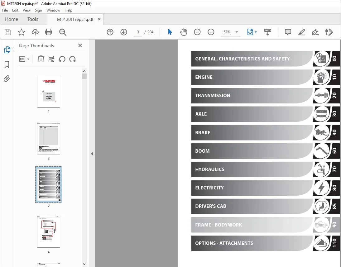
GENERAL, CHARACTERISTICS AND SAFETY 10
00 1 GENERAL INSTRUCTIONS AND SAFETY NOTICE 10
00 1 1 INTRODUCTION 10
00 1 2 SERVICING POSITION 10
00 1 3 EXPLANATION OF SYMBOLS 11
00 1 4 SERVICING RULES 12
00 2 GENERAL CHARACTERISTICS AND SPECIFICATIONS 15
00 2 1 CHARACTERISTICS 15
00 2 2 LUBRICANTS AND FUEL 15
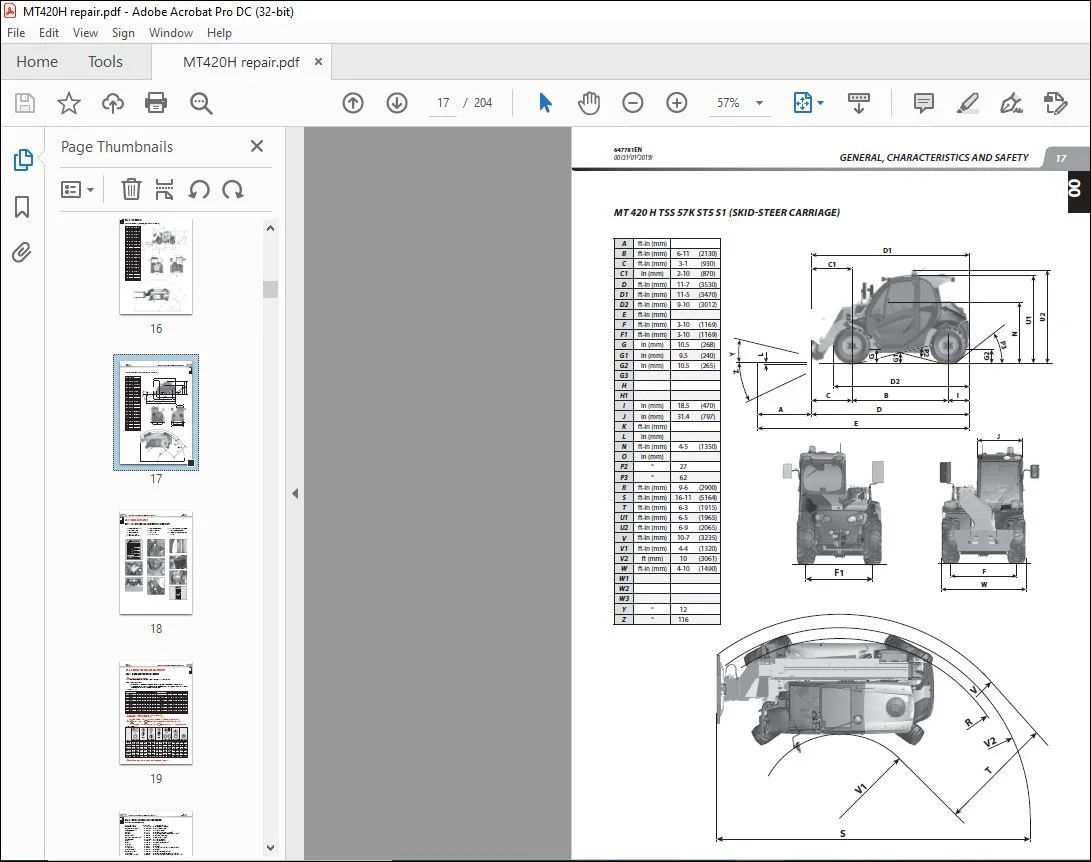
00 2 3 DIMENSIONS 16
MT 420 H 57K ST5 S1 (RS4-14) (Standard carriage) 16
MT 420 H TSS 57K ST5 S1 (Skid-steer carriage) 17
00 3 GENERAL LOCATION 18
00 3 1 LOCATION OF NAME AND IDENTIFICATION PLATE 18
00 4 GENERAL CONTROL AND ADJUSTMENT 19
00 4 1 STANDARD TIGHTENING TORQUES 19
00 4 2 METRIC – IMPERIAL UNIT CONVERSION 20
10 21
ENGINE 23
10 1 ENGINE CHARACTERISTICS AND SPECIFICATION 23
10 1 1 GENERAL CHARACTERISTICS 23
Engine V2607-CR-E5-B 23
10 1 2 REGENERATION CHARACTERISTICS 24
10 1 3 DECONTAMINATION PROMPT LEVELS (DEGRADED OPERATING MODES) 24
10 2 ENGINE CIRCUITS FLOW DIAGRAM 25
10 2 1 FUEL CIRCUIT: OVERVIEW OF THE FUEL SYSTEM 25
10 2 2 COOLING SYSTEM: LOWER BYPASS SYSTEM 25
10 2 3 EXHAUST CIRCUIT: AFTER-TREATMENT DEVICES 26
10 3 Engine components location 27
10 3 1 engine components 27
10 4 Engine controls and adjustments 28
10 4 1 Fan control 28
LOCATION 28
PURPOSE: 28
DESCRIPTION OF HYDRAULIC VENTILATION BLOCK: 29
Engine hydraulic diagram: 29
THE THREE MODES OF OPERATION: 30
ADJUSTMENT: 31
Fan control system architecture diagram: 32
10 4 2 ENGINE SILENT BLOCK TIGHTENING TORQUES 33
10 4 3 COOLING SYSTEM TIGHTENING TORQUES 33
10 5 Engine removal – refitting 34
PREPARATION AND SAFETY INSTRUCTIONS 34
10 5 1 Side casing and engine cover removal 34
10 5 2 Remove engine rear casing and mudguard 35
10 5 3 Alternator belt removal/refit 35
10 5 4 Alternator removal 35
10 5 5 STARTER removal 36
10 5 6 Air filter assembly removal 36
10 5 7 Cooler removal 37
Ventilation grille removal 37
RADIATOR removal 38
Ventilation control block removal 38
Cooler support bracket removal 39
10 5 8 Exhaust pipe removal 39
10 5 9 Fuel tank removal 41
10 5 10 Engine removal 42
10 5 11 Engine refit 46
10 5 12 Water pump removal 46
10 6 Engine troubleshooting 46
10 7 Specific engine tooling 46
10 7 1 Special engine tooling 46
10 7 2 Electronic tension meter 46
20 47
TRANSMISSION 49
20 1 Transmission schematic diagrams 49
20 1 1 DRIVE TRAIN 49
20 1 2 Key to diagrams 50
20 1 3 FORWARD GEAR Diagram 51
20 1 4 REVERSE GEAR Diagram 52
20 1 5 HYDROSTATIC TRANSMISSION PRESSURE TEST PORT LOCATION 53
20 1 6 TOWING PROCEDURE 54
20 1 7 TRANSMISSION TIGHTENING TORQUES 55
20 2 Transmission removal – refit 56
PREPARATION AND SAFETY INSTRUCTIONS 56
20 2 1 HYDROSTATIC PUMP REMOVAL 56
20 2 2 HYDROSTATIC MOTOR REMOVAL 59
20 3 Specific transmission tooling 61
20 3 1 BASIC MANOMETER BOX 61
20 3 2 DIGITAL MANOMETER BOX 62
30 63
AXLE 64
30 1 Axle control and adjustment 64
30 1 1 Tightening torques 64
40 65
BRAKE 67
40 1 BRAKE CHARACTERISTICS AND SPECIFICATIONS 67
40 1 1 SERVICE BRAKE / PARKING BRAKE 67
40 2 Brake controls and adjustment 68
40 2 1 BRAKE AND INCHING PEDAL ADJUSTMENT 68
Adjusting procedure: 68
BRAKE AND INCHING PHASES: REST, BRAKING AND ASSOCIATED VALUES FOR TRANSMISSION ECU: 68
40 2 2 BLEEDING PROCEDURE 69
LOCATION: 69
Bleed the brake calliper: 69
Bleed the brake master cylinder: 70
40 3 Specific brake tooling 72
40 3 1 BRAKE FLUID BLEEDER 72
50 73
BOOM 75
50 1 Boom removal – refit 75
PREPARATION AND SAFETY INSTRUCTIONS 75
50 1 1 Telescopic Cylinder Removal 75
50 1 2 Telescope removal 77
50 1 3 Telescope reassembly 79
50 1 4 Complete boom removal 81
70 85
HYDRAULICS 87
70 1 Hydraulic characteristics and specifications 87
70 1 1 Hydraulic component sheets 87
DISTRIBUTOR 5000 (INLET ELEMENTS) 87
DISTRIBUTOR 5000 (TILTING ELEMENT) 89
DISTRIBUTOR 5000 (ATTACHMENT ELEMENT) 91
DISTRIBUTOR 5000 (TELESCOPING ELEMENT) 93
DISTRIBUTOR 5000 (LIFTING ELEMENT) 95
CONTROL ACCUMULATOR BLOCK 97
STEERING PUMP/STEERING UNIT OSPC 160 LS 98
3-POSITION STEERING SELECTOR 100
FAN CONTROL UNIT + (FAN REVERSE OPTION) 101
COUNTERBALANCE VALVE VBSN 102
COMPENSATION INSULATION VALVE VIC 103
70 2 Hydraulic schematic diagrams 104
70 2 1 Key 104
70 2 2 Diagram 105
70 3 Hydraulic component locations 106
70 3 1 Key 106
70 4 Hydraulics removal – refit 107
PREPARATION AND SAFETY INSTRUCTIONS 107
70 4 1 Hydraulic pump removal 107
70 4 2 Main hydraulic tank removal 107
70 4 3 Suction strainer removal 109
70 4 4 Accumulator block removal 110
70 4 5 Control unit and distributor assembly removal 110
70 4 6 Lifting cylinder removal 111
70 4 7 Compensating cylinder removal 113
70 4 8 Tilting cylinder removal 114
80 115
ELECTRICITY 118
80 1 Electricity characteristics and specifications 118
80 1 1 Location of relays and fuses 118
80 1 2 Electrical network architecture 119
80 1 3 ECU INPUTS/OUTPUTS 120
X13 – DASHBOARD MODULE (BAUSER) – A1 120
X291 / X295 / X298 / X299 – TRANSMISSION ECU – A2 121
X55 – Main ECU SPU 40-26 (A3) 122
X56 – Main ECU SPU 40-26 (A3) 123
X57 – Main ECU SPU 40-26 (A3) 124
X174 – ENGINE ECU – ECM – A13 125
X175- ENGINE ECU – ECM – A13 126
80 1 4 TECHNICAL SHEETS FOR ELECTRICAL COMPONENTS 127
X1 / X2 – STARTER IGNITION SWITCH (S2) 127
X6 – Rotating beacon light (E15) 127
X11 / 12 – windscreen wiper commutator switch (S28) 128
X14 – lighting commutator switch (S26) 128
X22-1 / X22-2 – brake fluid level switch (S11) 129
X38 – REVERSING BUZZER (B1) 129
X39 – HORN (B2) 130
X62 – TRANSMISSION SPEED SENSOR (B13) 130
x63 – fuel gauge (B34) 131
X65 / X66 – WHEEL ALIGNMENT SENSOR (B12 / B24) 132
X67 / X68 – JSM (A4) 133
X77A / X77B – BMEP (A14) 134
X134 – BOOM RETRACTED SWITCH (S34) 135
X139 – Inching brake pedal angle sensor (B9) 135
X199 – Warm Up ELECTROVALVE (oil heater) (Y23) 136
X295 – FORWARD AND REVERSE ELECTROVALVE (y3 / Y4) 136
X325 – Air-conditioning thermostat sensor supplied with the thermostat (Y17) 137
X385 – VENTILATION CONTROL ELECTROVALVE (Y19) 137
X386 – VENTILATION REVERSAL ELECTROVALVE (OPTIONAL) (Y20) 138
80 2 WIRING DIAGRAMS 139
80 2 1 ELECTRICAL DIAGRAM CODIFICATION EXAMPLE 139
80 2 2 CABLE IDENTIFICATION ON A WIRING HARNESS 140
80 2 3 POSITIONS BY DIAGRAM 141
80 2 4 ELECTRICAL DIAGRAMS BY FUNCTION 144
Diagram 1 – STARTING 144
Diagram 2 – Networks (CAN & lin) 146
Diagram 3 – Transmission 148
Diagram 4 – Hydraulic movements 150
Diagram 5 – Sensors 152
Diagram 6 – Ventilation and wipers 154
Diagram 7 – Options 156
Diagram 8 – Lights and signals 158
Diagram 9 – KUBOTA ENGINE sensors 160
80 3 Electricity locations 161
80 3 1 Key 161
80 3 2 Main Harness 3D 163
80 3 3 MAIN Harness 2D 164
80 3 4 Engine 3D harness 165
80 3 5 Engine 2D harness 166
80 3 6 8 electrovalve hydraulic block 2D harness 167
DASHBOARD CALIBRATION MENU 168
CALIBRATION MODE: ACTIVATION 168
CALIBRATION SELECTION 168
LIFT TRUCK SERIAL NUMBER DISPLAY 168
RESETTING THE PARTIAL HOUR METER 168
INCHING BRAKE PEDAL CALIBRATION 169
TELESCOPING SPEED CALIBRATION 169
ATTACHMENT FLOW RATE CALIBRATION 170
FORCED OPERATION 171
MAINTENANCE HOUR METER RESET 171
SELECTION OF SPEED UNIT KM/H OR MPH 171
80 3 7 Removal – Refit of JSM on BMEP 172
80 4 Electrical troubleshooting 173
80 4 1 Reading of error codes 173
DASHBOARD ERROR CODES 173
PAD ERROR CODES 173
80 4 2 DTC DASHBOARD MODULE ECU (BAUSER) – (X13 ECU-A1) 174
80 4 3 DTC Main ECU (X55 – X56 – X57 – SPU 40-26-A3) 174
80 4 4 DTC Transmission ECU (X291 / X295 / X298 / X299 – ECU A2) 177
80 4 5 ENGINE ECU DTC (X174 / X175 – ECM A13) 178
80 5 Specific electric tooling 179
80 5 1 Diagnostic tools 179
Version 1 179
Version 2 181
Engine adaptation kit 182
80 5 2 Breakout boxes 183
85 185
DRIVER’S CAB 186
85 1 DRIVER’S CAB CONTROL AND ADJUSTMENT 186
85 1 1 TIGHTENING TORQUES 186
CAB SILENT BLOCK 186
PREPARATION AND SAFETY INSTRUCTIONS 186
85 2 Driver’s cab removal – refit 187
85 2 1 Removing the cabin 187
85 2 2 Refitting the cab 191
110 193
OPTIONS – ATTACHMENTS 194
110 AIR CONDITIONING OPTION 194
110 1 Air conditioning characteristics and specifications 194
110 1 1 Description of air-conditioning operation 194
110 1 2 Principle of air-conditioning operation 195
110 1 3 Description of air-conditioning components 196
110 2 Air conditioning controls and adjustments 197
110 2 1 Safety measures for handling air-conditioning R134a 197
110 2 2 ASSEMBLY INSTRUCTIONS FOR AIR CONDITIONING CIRCUIT 197
110 2 3 Air-conditioning R134a REFRIGERANT FLUID CHARACTERISTICS 199
110 2 4 Refrigerant fluid load for the air conditioning circuit 199
110 2 5 Air-conditioning CHARGING METHOD 199
110 2 6 Air-conditioning OPERATIONAL CHECK 200
110 3 Air-conditioning troubleshooting 203
110 3 1 Air-conditioning FAULT DIAGNOSTICS 203
FAULTY AIR-CONDITIONING 203
FAULTY VENTILATION 204
FAULTY HEATING 204
PLEASE NOTE:
- This is the SAME exact manual used by your dealers to fix your vehicle.
- The same can be yours in the next 2-3 mins as you will be directed to the download page immediately after paying for the manual.
- Any queries / doubts regarding your purchase, please feel free to contact [email protected]
S.V