Manitou HYDROSTATIC PUMP H1 045-053-060-068 Lift Truck Repair Manual 647039 – PDF DOWNLOAD
Original price was: $75.95.$19.95Current price is: $19.95.
Manitou HYDROSTATIC PUMP H1 045-053-060-068 Lift Truck Repair Manual 647039 – PDF DOWNLOAD
Description
Manitou HYDROSTATIC PUMP H1 045-053-060-068 Lift Truck Repair Manual 647039 – PDF DOWNLOAD
IMAGES PREVIEW OF THE MANUAL:
DESCRIPTION:
Manitou HYDROSTATIC PUMP H1 045-053-060-068 Lift Truck Repair Manual 647039 – PDF DOWNLOAD
- This manual details major repair procedures for H1 pumps. These include the complete disassembly,
inspection, and reassembly of the unit. Where rework of worn or damaged components is possible,
specifications appear to ensure these parts meet factory tolerances. - Only Danfoss Global Service Partners
(GSPs) are authorized to perform major repairs. Danfoss trains Global Service Partners and certifies their
facilities on a regular basis. - Minor repair procedures, adjustments, and troubleshooting information appear in the H1 078/147/165
Closed Circuit Axial Piston Pumps Service Manual, 520L0848. Minor repairs include service operations you
can perform without removing the unit’s endcap. Removal of the endcap voids your warranty.
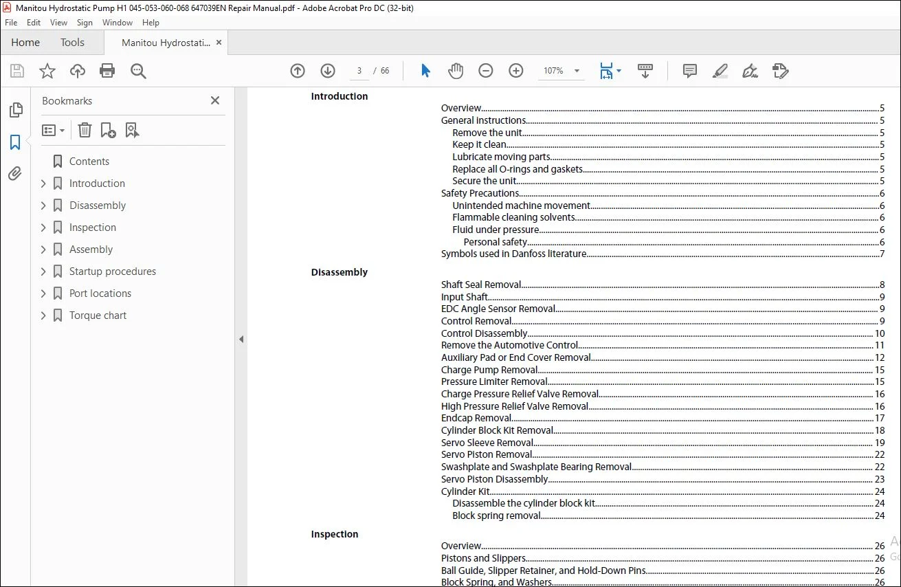
TABLE OF CONTENTS:
Manitou HYDROSTATIC PUMP H1 045-053-060-068 Lift Truck Repair Manual 647039 – PDF DOWNLOAD
Introduction
Overview 5
General instructions 5
Remove the unit 5
Keep it clean 5
Lubricate moving parts 5
Replace all O-rings and gaskets 5
Secure the unit 5
Safety Precautions 6
Unintended machine movement 6
Flammable cleaning solvents 6
Fluid under pressure 6
Personal safety 6
Symbols used in Danfoss literature 7
Disassembly
Shaft Seal Removal 8
Input Shaft 9
EDC Angle Sensor Removal 9
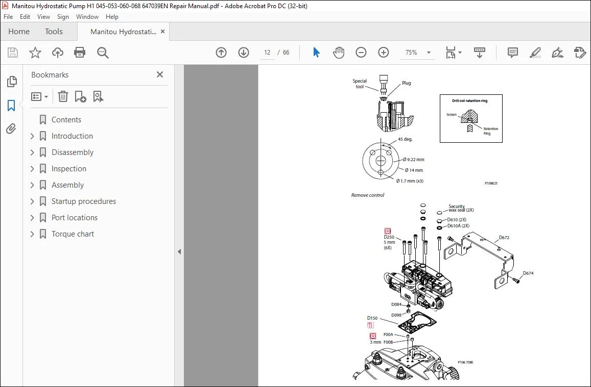
Control Removal 9
Control Disassembly 10
Remove the Automotive Control 11
Auxiliary Pad or End Cover Removal 12
Charge Pump Removal 15
Pressure Limiter Removal 15
Charge Pressure Relief Valve Removal 16
High Pressure Relief Valve Removal 16
Endcap Removal 17
Cylinder Block Kit Removal 18
Servo Sleeve Removal 19
Servo Piston Removal 22
Swashplate and Swashplate Bearing Removal 22
Servo Piston Disassembly 23
Cylinder Kit 24
Disassemble the cylinder block kit 24
Block spring removal 24
Inspection
Overview 26
Pistons and Slippers 26
Ball Guide, Slipper Retainer, and Hold-Down Pins 26
Block Spring, and Washers 26
Cylinder Block 27
Shaft 27
Shaft Bearing 27
Swashplate 28
Valve Plate 28
Endcap 29
Housing 29
Pressure Limiter 30
HPRV Valve 30
Cradle Bearings 31
Optional Displacement Limiter 32
Charge Pressure Relief Valve 32
Servo Piston Assembly 32
Control 33
Assembly
Overview 34
Shaft and Seal Installation 34
Cradle Bearings and Swashplate Installation 35
Repair Instructions
H1 45/53/60/68 Closed Circuit Axial Piston Pumps
Contents
© Danfoss | May 2018 520L0957 | AX00000194en-000303 | 3
Servo Piston Assembly 37
Servo Piston Installation 38
Servo Cylinder Installation 38
Cylinder Kit Assembly 40
Cylinder Kit Installation 41
Timing Pin and Endcap Bushing Installation 41
Endcap Bushing Installation tools 42
Endcap Bushing Orientation 43
Valve Plate and Endcap Installation 43
Charge Pump Installation 45
Auxiliary Pad or End Cover Installation 46
Charge Pressure Relief Valve Installation 48
Pressure Limiter Installation 48
HPRV Valve Installation 49
Optional Displacement Limiter Installation 50
EDC Angle Sensor Assembly 50
EDC Control with Angle Sensor Installation 51
Control Assembly 53
Control Installation 55
MDC Control 56
Automotive Control Installation 59
Startup procedures
Overview 61
Initial Startup Procedures 61
Adjustments 61
Pressure Measurements 61
Port locations
Port Locations and Gauge Installation 62
Torque chart
Fastener Size and Torque Chart 63
Plug Size and Torque Chart 63
Fasteners and Plugs 64
Customer Support: [email protected]
PLEASE NOTE:
- This is the SAME manual used by the dealers to troubleshoot any faults in your vehicle. This can be yours in 2 minutes after the payment is made.
- Contact us at [email protected] should you have any queries before your purchase or that you need any other service / repair / parts operators manual.
S.V