Manitou MLT 635 733 737 741 940 ST4 S2-S3, MLT-X 737 741 ST3A S1 Repair Manual 647681EN – PDF DOWNLOAD
Original price was: $86.95.$29.95Current price is: $29.95.
Manitou MLT 635 733 737 741 940 ST4 S2-S3, MLT-X 737 741 ST3A S1 Repair Manual 647681EN – PDF DOWNLOAD
647681EN (14/04/2020)
MLT 635 130 PS D ST4 S2
MLT 733 105/115 D ST4 S2/S3
MLT 733 105/115 D ST4 S2/S3 TRACT
MLT 733 105/115 D ST4 S2/S3 TRACT LSU
MLT 737 130 PS D ST4 S2
MLT 635 140 V PLUS D ST4 S2
MLT 741 140 V PLUS D ST4 S2
MLT 940 140 V PLUS D ST4 S2
MLT-X 737 130 PS D ST3A S1
MLT-X 741 140 V PLUS D ST3A S1
MANUEL DE RÉPARATION
Description
Manitou MLT 635 733 737 741 940 ST4 S2-S3, MLT-X 737 741 ST3A S1 Repair Manual 647681EN – PDF DOWNLOAD
FILE DETAILS:
Manitou MLT 635 733 737 741 940 ST4 S2-S3, MLT-X 737 741 ST3A S1 Repair Manual 647681EN – PDF DOWNLOAD
Language : English
Pages : 484
Downloadable : Yes
File Type : PDF
Size: 135 MB
IMAGES PREVIEW OF THE MANUAL:
Questions? Email us: [email protected]
https://vimeo.com/777272508
DESCRIPTION:
Manitou MLT 635 733 737 741 940 ST4 S2-S3, MLT-X 737 741 ST3A S1 Repair Manual 647681EN – PDF DOWNLOAD
647681EN (14/04/2020)
MLT 635 130 PS D ST4 S2
MLT 733 105/115 D ST4 S2/S3
MLT 733 105/115 D ST4 S2/S3 TRACT
MLT 733 105/115 D ST4 S2/S3 TRACT LSU
MLT 737 130 PS D ST4 S2
MLT 635 140 V PLUS D ST4 S2
MLT 741 140 V PLUS D ST4 S2
MLT 940 140 V PLUS D ST4 S2
MLT-X 737 130 PS D ST3A S1
MLT-X 741 140 V PLUS D ST3A S1
MANUEL DE RÉPARATION
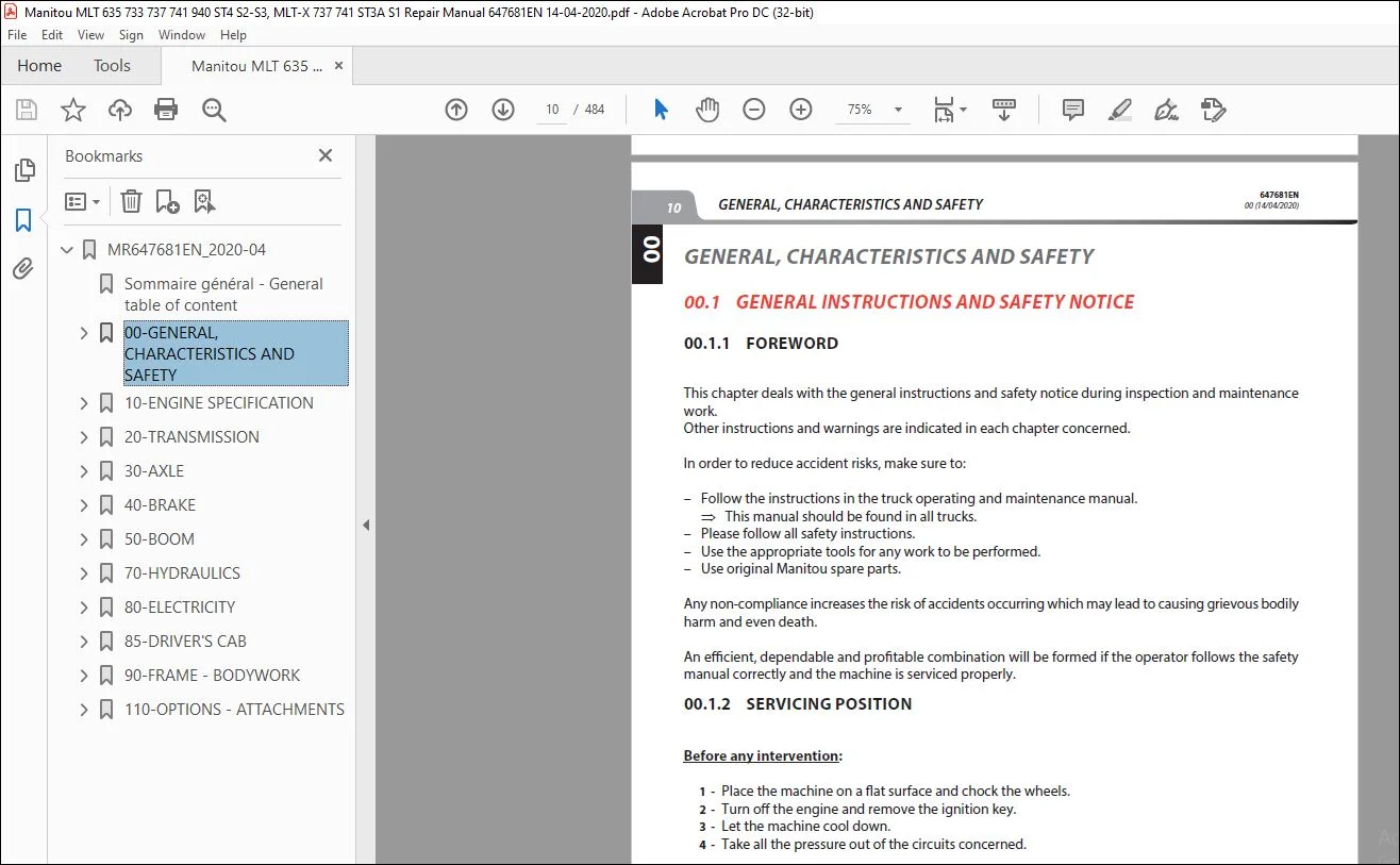
GENERAL INSTRUCTIONS AND SAFETY NOTICE
00.1.1 FOREWORD
This chapter deals with the general instructions and safety notice during inspection and maintenance
work.
Other instructions and warnings are indicated in each chapter concerned.
In order to reduce accident risks, make sure to:
– Follow the instructions in the truck operating and maintenance manual.
⇒ This manual should be found in all trucks.
– Please follow all safety instructions.
– Use the appropriate tools for any work to be performed.
– Use original Manitou spare parts.
Any non-compliance increases the risk of accidents occurring which may lead to causing grievous bodily
harm and even death.
An effi cient, dependable and profi table combination will be formed if the operator follows the safety
manual correctly and the machine is serviced properly.
TABLE OF CONTENTS:
Manitou MLT 635 733 737 741 940 ST4 S2-S3, MLT-X 737 741 ST3A S1 Repair Manual 647681EN – PDF DOWNLOAD
MR647681EN_2020-04……………………………………………………………………… 1
Sommaire général – General table of content……………………………………………. 3
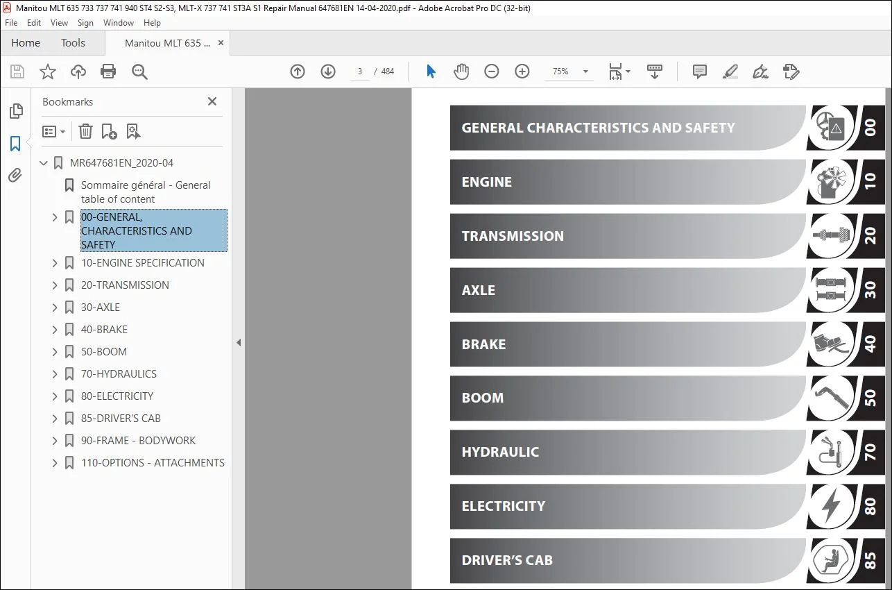
00-GENERAL, CHARACTERISTICS AND SAFETY………………………………………………… 9
00.1 GENERAL INSTRUCTIONS AND SAFETY NOTICE………………………………………… 10
00.1.1 FOREWORD……………………………………………………………… 10
00.1.2 SERVICING POSITION…………………………………………………….. 10
00.1.3 EXPLANATION OF SYMBOLS…………………………………………………. 11
00.1.4 SERVICING RULES……………………………………………………….. 12
00.2 GENERAL CHARACTERISTICS AND SPECIFICATIONS…………………………………….. 15
00.2.1 CHARACTERISTICS……………………………………………………….. 15
00.2.2 LUBRICANTS AND FUEL……………………………………………………. 15
00.2.3 DIMENSIONS……………………………………………………………. 16
MLT 635 / MLT 737………………………………………………………… 16
MLT 733 / MLT 733 TRACT / MLT 733 TRACT LSU ………………………………… 17
MLT 635 / MLT 741 – 140 V PLUS…………………………………………….. 18
MLT 940 – 140 V PLUS……………………………………………………… 19
00.3 GENERAL LOCATION……………………………………………………………. 20
00.3.1 NAME AND IDENTIFICATION PLATE…………………………………………… 20
00.4 GENERAL CONTROL AND ADJUSTMENT……………………………………………….. 21
00.4.1 STANDARD TIGHTENING TORQUES…………………………………………….. 21
00.4.2 METRIC – IMPERIAL UNIT CONVERSION……………………………………….. 22
10-ENGINE SPECIFICATION……………………………………………………………… 23
10.1 Engine characteristics and specifications……………………………………… 25
10.1.1 Characteristics……………………………………………………….. 25
10.1.2 Diesel exhaust fluid (DEF)……………………………………………… 25
10.1.3 Injection cycle……………………………………………………….. 26
10.1.4 Bosch CP4.1 high pressure pump………………………………………….. 27
10.2 Engine Schematic Diagrams……………………………………………………. 28
10.2.1 Air intake circuit and EGR (Exhaust Gas Recirculation)…………………….. 28
10.2.2 Lubrication circuit……………………………………………………. 29
10.2.3 Cooling circuit……………………………………………………….. 30
10.2.4 Fuel circuit………………………………………………………….. 31
10.2.5 DEF (Diesel Exhaust Fluid) circuit………………………………………. 32
10.3 Engine components location…………………………………………………… 33
10.3.1 Engine components……………………………………………………… 33
10.3.2 Water and air cooling circuit…………………………………………… 35
10.3.3 Ventilation hydraulic circuit…………………………………………… 36
10.3.4 Diesel circuit………………………………………………………… 37
10.3.5 Fuel injection circuit…………………………………………………. 38
10.3.6 EGR (Exhaust Gas Recirculation) circuit………………………………….. 39
10.3.7 DEF (Diesel Exhaust Fluid) circuit………………………………………. 40
10.4 Engine controls and adjustments………………………………………………. 41
10.4.1 Engine start-up authorization conditions…………………………………. 41
10.4.2 DEF regeneration………………………………………………………. 41
10.4.3 DEF pump cleaning procedure…………………………………………….. 42
10.4.4 Engine load level……………………………………………………… 46
10.4.5 Ventilation regulation (MLT 733 as option)……………………………….. 47
A – function…………………………………………………………….. 47
B – principle of operation………………………………………………… 47
C – schematic diagram…………………………………………………….. 48
D – description of hydraulic engine with control…………………………….. 48
E – conditions of fan control-related components…………………………….. 49
10.4.6 Silent block tightening torques…………………………………………. 50
10.4.7 Engine tightening torques………………………………………………. 50
10.4.8 Diesel fuel circuit tightening torques…………………………………… 51
10.4.9 Exhaust circuit tightening torques………………………………………. 51
Assembly on MLT-X………………………………………………………… 51
Assembly on MLT………………………………………………………….. 52
10.4.10 Cooling circuit tightening torques……………………………………… 53
10.4.11 Heating circuit tightening torques……………………………………… 54
10.5 Engine removal – refitting…………………………………………………… 54
10.5.1 Engine ECU removal – refit……………………………………………… 54
10.5.2 Air filter assembly removal…………………………………………….. 55
10.5.3 Starter motor removal………………………………………………….. 58
10.5.4 DOC exhaust pipe removal……………………………………………….. 59
10.5.5 Remove the “SCR” pipe………………………………………………….. 60
10.5.6 DEF injector removal…………………………………………………… 61
10.5.7 DEF tank removal………………………………………………………. 62
DEF gauge removal………………………………………………………… 63
10.5.8 Cooler removal………………………………………………………… 64
Removing the upper part…………………………………………………… 64
Separation of cooler from engine…………………………………………… 66
Option 1: removal of pump and grill………………………………………… 69
Option 2: removal of cooler assembly……………………………………….. 70
10.5.9 Remove the engine……………………………………………………… 71
Engine hose and connector removal………………………………………….. 72
Engine/Angle gear box transmission universal joint removal……………………. 74
10.5.10 ATTACHMENT BELT REMOVAL……………………………………………….. 75
10.5.11 Engine refit…………………………………………………………. 76
10.5.12 Alternator removal……………………………………………………. 76
10.5.13 Water pump removal……………………………………………………. 76
10.5.14 Turbo-compressor removal. …………………………………………….. 76
10.6 Engine troubleshooting………………………………………………………. 77
10.7 Specific engine tooling……………………………………………………… 77
10.7.1 Special engine tooling…………………………………………………. 77
10.7.2 Electronic tension meter……………………………………………….. 77
10.7.3 DEF flush kit…………………………………………………………. 78
20-TRANSMISSION…………………………………………………………………….. 79
20.1 Transmission schematic diagrams………………………………………………. 81
20.1.1 Compact+ (C+) manual gearbox……………………………………………. 81
C+ DRIVE TRAIN…………………………………………………………… 81
C+ OPERATION OVERVIEWS……………………………………………………. 82
Summary table of connectors concerned by functions (C+)………………………. 83
20.1.2 POWERSHIFT (PS – PG 115) gearbox………………………………………… 83
PS DRIVE TRAIN…………………………………………………………… 83
PS OPERATION OVERVIEWS……………………………………………………. 84
Summary table of connectors concerned by functions (PS)………………………. 85
20.1.3 Hydrostatic gearbox (zf 2 HC 85)………………………………………… 86
DRIVE TRAIN……………………………………………………………… 86
OPERATION OVERVIEWS (ZF 2 hc 85)…………………………………………… 87
pressure connectors………………………………………………………. 88
20.2 Transmission locations………………………………………………………. 88
20.2.1 MECHANICAL TRANSMISSION AND GEARBOX COOLING………………………………. 88
20.2.2 POWERSHIFT (PG 115) GEARBOX COMPONENTS…………………………………… 89
20.2.3 Hydrostatic TRANSMISSION (zf 2 HC 85)……………………………………. 90
20.3 Transmission controls and adjustments…………………………………………. 91
20.3.1 Hydrostatic auto-calibration……………………………………………. 91
20.3.2 Verification of machine configurations…………………………………… 92
20.3.3 General authorisation conditions for carriage movement…………………….. 92
Acquisition conditions……………………………………………………. 92
Upkeep conditions………………………………………………………… 92
Loss conditions………………………………………………………….. 92
20.3.4 Powershift – PG115 gearbox……………………………………………… 92
ECU Transmission (X322)…………………………………………………… 92
Automatic gear change mode………………………………………………… 93
Table of maximum speeds per gear…………………………………………… 93
SHAFT AND CLUTCH…………………………………………………………. 94
GEAR SET………………………………………………………………… 94
DRIVE TRAIN……………………………………………………………… 95
TABLE OF PRESSURES……………………………………………………….. 96
PRESSURE TEST PORT LOCATIONS………………………………………………. 97
20.3.5 Hydrostatic gearbox (zf 2 HC 85)………………………………………… 98
Operating mode – 2 HC 85………………………………………………….. 99
Key for HYDROSTATIC CIRCUITS 2 HC-85………………………………………..101
Diagram: Neutral………………………………………………………….102
Diagram: drive range 1…………………………………………………….103
Diagram: drive range 2…………………………………………………….104
Diagram: drive range 3…………………………………………………….105
20.3.6 TRANSMISSION TIGHTENING TORQUES………………………………………….106
MLT 635 – 737 PS………………………………………………………….106
MLT 733………………………………………………………………….107
MLT 635 – 741 – 940 V PLUS…………………………………………………108
20.3.7 Changing to freewheel mode (Mechanical transmission)……………………….108
20.3.8 Changing to freewheel mode (Hydrostatic transmission)………………………108
After towing……………………………………………………………..109
20.4 Transmission removal – refit………………………………………………….109
20.4.1 Remove the Powershift gear box…………………………………………..109
20.4.2 Removal of the manual gearbox assembly – angle transmission…………………112
20.4.3 Remove the hydrostatic gearbox (zf 2 HC 85)……………………………….117
20.4.4 Remove the hydrostatic pump……………………………………………..120
Remove the hydraulic pump………………………………………………….120
Remove the hydrostatic pump………………………………………………..121
20.5 Specific transmission tooling…………………………………………………123
20.5.1 BASIC MANOMETER BOX…………………………………………………….123
20.5.2 DIGITAL MANOMETER BOX…………………………………………………..124
20.5.3 Hydrostatic gearbox removal tool…………………………………………125
30-AXLE…………………………………………………………………………….127
30.1 Axle controls and adjustments…………………………………………………128
30.1.1 Tightening torques……………………………………………………..128
40-BRAKE……………………………………………………………………………131
40.1 Brake characteristics and specifications……………………………………….133
40.1.1 Service brake………………………………………………………….133
Assembly with master cylinder………………………………………………133
Assembly with hydraulic valve………………………………………………134
40.1.3 Trailer brake valve…………………………………………………….135
40.1.4 Accumulator load valve………………………………………………….136
40.1.5 Service brake valve 55 b………………………………………………..137
40.2 Service brake schematic diagrams………………………………………………138
40.2.1 Brake valve (VAFS) operating principle……………………………………138
Engine on, pump running, pedal at rest………………………………………138
Engine on, pump running, pedal activated…………………………………….138
Engine off, pump shut down, pedal activated………………………………….139
40.3 Brake locations……………………………………………………………..140
40.3.1 Brake locations – Mechanical transmission…………………………………140
MLt 635/737 – MLT 733 S2/S3 Tract+LSU (Up to machine no. MAN00000K01007220 )…….140
MLt 635/737 – MLT 733 S3 Tract+LSU (up to machine no. MAN00000K01007221)………..140
Brake system location – MLT 733 S2/S3……………………………………….141
40.3.2 Brake locations – Hydrostatic transmission………………………………..141
40.4 Brake controls and adjustment…………………………………………………142
40.4.1 TRAILER BRAKE VALVE TIGHTENING TORQUE…………………………………….142
40.4.2 Adjustment of parking brake on gearbox……………………………………142
for machines before tractor standard 167-2013………………………………..142
40.4.3 Adjustment of parking brake on front axle…………………………………145
For tractor standard 167-2013 machines………………………………………145
40.4.4 Adjusting the brake pedal……………………………………………….150
MLT 733 105 D…………………………………………………………….150
MLT 635/737 130 PS – MLT 733 105 D Tract (up to machine no.)…………………..151
MLT 635/737 130 PS – MLT 733 115 D Tract (from machine no.)……………………152
MLT 635/741/940 140 v plus…………………………………………………153
40.4.5 Calibrate the inching pedal……………………………………………..153
40.4.6 Bleed the brakes……………………………………………………….154
40.4.7 Taking brake pressure on MLT 140 V PLUS…………………………………..155
40.4.8 Towing the lift truck…………………………………………………..155
Mechanical transmission …………………………………………………..155
Hydrostatic transmission…………………………………………………..155
40.5 Brake removal – refit………………………………………………………..156
40.5.1 Brake master cylinder on mlt ps………………………………………….156
40.6 Specific brake tooling……………………………………………………….157
40.6.1 BRAKE FLUID BLEEDER…………………………………………………….157
50-BOOM…………………………………………………………………………….159
50.1 BOOM CHARACTERISTICS AND SPECIFICATIONS………………………………………..160
50.1.1 DUPLEX BOOMS…………………………………………………………..160
50.1.2 TRIPLEX BOOMS………………………………………………………….160
50.2 BOOM location……………………………………………………………….161
50.2.1 DUPLEX BOOM (6 and 7 m)…………………………………………………161
50.2.2 TRIPLEX BOOM (9 m)……………………………………………………..162
50.3 BOOM CONTROL AND ADJUSTMENT…………………………………………………..163
50.3.1 TELESCOPE EXTENSION AND RETRACTION ADJUSTMENT PROCEDURE…………………….163
TELESCOPE EXTENSION SPEED ADJUSTMENT (TRIPLEX BOOM)…………………………..163
TELESCOPE RETRACTION SPEED ADJUSTMENT (DUPLEX AND TRIPLEX BOOM)………………..163
INNER TELESCOPE RETRACTION DE-SYNCHRONISATION (TRIPLEX BOOM)…………………..163
50.3.2 RECOMMENDATION FOR FITTING SHIMS AND LUBRICATION…………………………..164
50.3.3 Duplex TIGHTENING TORQUE AND LUBRICATION………………………………….165
50.3.4 Triplex TIGHTENING TORQUE AND LUBRICATION…………………………………166
50.4 Removal – refit……………………………………………………………..167
50.4.1 duplex boom……………………………………………………………167
Telescope removal…………………………………………………………167
Telescope removal…………………………………………………………169
Telescopic Cylinder Removal………………………………………………..170
Refit:…………………………………………………………………..172
50.4.2 triplex boom…………………………………………………………..173
PREPARATION AND SAFETY INSTRUCTIONS…………………………………………173
Telescoping circuit removal………………………………………………..173
BOOM HEAD TELESCOPE T2 REMOVAL……………………………………………..177
INTERMEDIATE TELESCOPE T1 REMOVAL…………………………………………..178
50.5 Special boom tools…………………………………………………………..179
50.5.1 FLARE NUT WRENCHES……………………………………………………..179
50.5.2 MAGNETIC LIFTER………………………………………………………..179
70-HYDRAULICS……………………………………………………………………….181
70.1 Hydraulic characteristics and specifications……………………………………183
70.1.1 Dynamic steering operation………………………………………………183
70.1.2 Hydraulic component sheets ……………………………………………..185
Accumulator block…………………………………………………………185
OSPC 200 LS steering block…………………………………………………187
Pilot safety valve………………………………………………………..189
Pilot safety valve………………………………………………………..191
Distributor RS 14…………………………………………………………193
Distributor SDS 140……………………………………………………….199
FAN REGULATOR MOTOR (FAN DRIVE)…………………………………………….200
Casappa MVP 60 – 63 pump…………………………………………………..204
HYDROSTATIC pump LA10V072EK1DS/53R………………………………………….207
70.2 Hydraulic schematic diagrams………………………………………………….209
70.2.1 Key S2………………………………………………………………..209
70.2.2 Key S3………………………………………………………………..210
70.2.3 Diagram MLT 635-737 130 PS D ST4 S2 (1st fit)……………………………..212
70.2.4 Diagram MLT 635-737 130 PS D ST4 S2 (2nd fit) + mlt-x 737 130 ps d st3a s1……213
70.2.5 Diagram MLT 733 105 D ST4 S2 ……………………………………………214
70.2.6 Diagram MLT 733 105 D ST4 S2 TRACT……………………………………….215
70.2.7 Diagram MLT 733 105 d ST4 S2 TRACT LSU……………………………………216
70.2.8 Diagram MLT 635/741/940 140 V Plus D ST4 S2 + MLT-X 741 140 V Plus D ST3A S1….217
70.2.9 Diagram MLT 733 115 D ST4 S3…………………………………………….218
70.2.10 Diagram MLT 733 115 D ST4 S3 TRACT………………………………………219
70.2.11 Diagram MLT 733 115 D ST4 S3 TRACT LSU…………………………………..220
70.3 Hydraulic locations………………………………………………………….221
70.3.1 Key………………………………………………………………….221
70.4 Hydraulic controls and adjustments…………………………………………….222
70.4.1 Flush the MLT 733 distributor (initial fitting)……………………………222
70.5 Hydraulics removal – refit……………………………………………………222
70.5.1 Remove the hydraulic pump……………………………………………….222
70.5.2 Lifting cylinder removal………………………………………………..224
70.5.3 Remove the distributor………………………………………………….226
70.6 Hydraulic specific tooling……………………………………………………228
70.6.1 Square bracket…………………………………………………………228
70.6.2 Distributor lifting device………………………………………………228
70.6.3 DIGITAL MANOMETER BOX…………………………………………………..229
70.6.4 BASIC MANOMETER BOX…………………………………………………….230
70.6.5 INFLATION KIT BOX………………………………………………………231
80-ELECTRICITY………………………………………………………………………233
80.1 Electricity characteristics and specifications………………………………….237
80.1.1 Location of relays and fuses…………………………………………….237
80.1.2 Screen menus…………………………………………………………..238
80.1.3 Electrical network architecture………………………………………….241
80.1.4 Electrical network architecture details…………………………………..242
80.1.5 ECU Inputs/Outputs……………………………………………………..243
X13/X25 – screen (A9)……………………………………………………..243
X14 – Navigator (A4)………………………………………………………244
X39-C10 – Air-conditioning ECU (A17)………………………………………..244
X80 – Main ECU SPU 40-26 (A2)………………………………………………245
X81 – Main ECU SPU 40-26 (A2)………………………………………………246
X82 – Main ECU SPU 40-26 (A2)………………………………………………247
X274 – Engine ECU EDC17CV52 (A19)…………………………………………..248
X275 – Engine ECU EDC17CV52 (A19)…………………………………………..249
X322 – Powershift gearbox ECU PG115 (A10) …………………………………..250
X356 – Auxiliary ECU SPU 25-15 (A3)…………………………………………251
X357 – Auxiliary ECU SPU 25-15 (A3)…………………………………………252
X400 – Gearbox ECU ZF – 2HC85 _ Box CVT (A10)………………………………..253
X401 – Gearbox ECU ZF – 2HC85 _ Box CVT (A10)………………………………..254
80.1.6 Technical sheets for electrical components………………………………..255
X1/X2 – starter ignition switch (A12)……………………………………….255
X10 – lighting commutator switch (S5)……………………………………….255
X11 / 12 – windscreen wiper commutator switch (S4)……………………………256
X34 – Outside air temperature sensor………………………………………..256
X56 – Rotating beacon light (e15)…………………………………………..257
X72 – Brake fluid level switch (S11)………………………………………..257
X74 – Accelerator potentiometer (B18)……………………………………….258
X75/X76 – JSM (A12)……………………………………………………….259
X77 – BMEP (A11)………………………………………………………….260
X78 – Manual accelerator…………………………………………………..261
X79 – stop pressure switch (B8)…………………………………………….261
X90 to X94 – DSB (Double Switch Board) (S61 to S76)…………………………..262
X121 – Brake pedal angular sensor (PS) (B47)…………………………………263
X225 – DEF tank gauge (B53)………………………………………………..264
X225 – DEF tank analog gauge (US) (B53)……………………………………..265
X245 – Supercharged air cooler temperature sensor…………………………….266
X246 – Transmission oil cooler temperature sensor…………………………….266
X247 – Hydraulic fluid cooler temperature sensor……………………………..267
X252 – VENTILATION CONTROL ELECTROVALVE……………………………………..267
X253 – VENTILATION inversion ELECTROVALVE……………………………………268
X265 – Fuel level sensor (R2)………………………………………………268
X300 – Angle boom potentiometer (B23)……………………………………….269
X334 – Telescope retracted position sensor (S34)……………………………..270
X382 – Brake circuit pressure switch (B30)…………………………………..270
80.2 Wiring diagrams……………………………………………………………..271
80.2.1 Examples of coding on the wiring diagrams…………………………………271
80.2.2 Cable marking on an electrical wiring harness……………………………..272
80.2.3 MLT 635/737 130 PS D ST4 S2 – MLT-X 737 130 ps d st3a s1……………………274
Positions of connectors by diagram………………………………………….274
Diagram 1 – Starting………………………………………………………276
Diagram 2 – Networks (CAN & lin)……………………………………………278
Diagram 3 – Transmission…………………………………………………..280
Diagram 4 – Hydraulics…………………………………………………….282
Diagram 5 – Sensor………………………………………………………..284
Diagram 6 – Ventilation, wipers and air conditioning………………………….286
Automatic air conditioning option…………………………………………..286
Diagram 7 – Options……………………………………………………….288
Diagram 8 – Lights and signals……………………………………………..290
80.2.4 MLT 733 105 D ST4 S2+ S3 + TRACT + LSU……………………………………292
Positions of connectors by diagram………………………………………….292
Diagram 1 – Starting………………………………………………………294
Diagram 2 – Networks (CAN & lin)……………………………………………296
Diagram 3 – Transmission…………………………………………………..298
Diagram 4 – Hydraulics…………………………………………………….300
Diagram 5 – Sensor………………………………………………………..302
Diagram 6 – Ventilation, wipers and air conditioning………………………….304
Automatic air conditioning option…………………………………………..304
Diagram 7 – Options……………………………………………………….306
Diagram 8 – Lights and signals……………………………………………..308
80.2.5 MLT 635/741/940 140 V plus d ST4 S2 – MLT-X 741 140 V plus d ST3a S1…………310
Positions of connectors by diagram………………………………………….310
Diagram 1 – Starting………………………………………………………312
Diagram 2 – CAN & lin networks……………………………………………..314
Diagram 3 – Transmission…………………………………………………..316
Diagram 4 – Hydraulics…………………………………………………….318
Diagram 5 – Sensor………………………………………………………..320
Diagram 6 – Ventilation, wipers and air conditioning………………………….322
Automatic air conditioning option…………………………………………..322
Diagram 7 – Options……………………………………………………….324
Diagram 8 – Lights and signals……………………………………………..326
80.3 Electricity locations………………………………………………………..328
80.3.1 MLT mechanical transmission……………………………………………..328
Key……………………………………………………………………..328
Frame 3D PS Harness……………………………………………………….331
Frame 3D Mechanical Harness ……………………………………………….332
Cab 3D mechanical & PS harness……………………………………………..333
Engine 3D MLT mechanical & PS harness……………………………………….334
Deutz engine 3D harness……………………………………………………335
Frame 2D PS Harness……………………………………………………….336
Frame 2D Mechanical Harness………………………………………………..337
Cab 2D harness……………………………………………………………338
Engine 2D harness…………………………………………………………339
Valve bank 2D harness……………………………………………………..340
80.3.2 MLT V plus…………………………………………………………….341
Key……………………………………………………………………..341
Frame 3D V plus harness……………………………………………………344
Cab 3D v plus harness …………………………………………………….345
Engine 3D MLT V plus harness……………………………………………….346
Deutz engine 3D harness……………………………………………………347
Frame 2D V plus harness……………………………………………………348
Cab 2D V PLUS harness……………………………………………………..349
Engine 2D harness…………………………………………………………350
Valve bank 2D harness……………………………………………………..351
80.4 Electrical removal – refit……………………………………………………352
80.4.1 Remove the battery……………………………………………………..352
80.4.2 Remove the engine ECU…………………………………………………..353
Refit……………………………………………………………………353
80.4.3 Remove the main ECU “SPU 40-26”………………………………………….354
80.4.4 Remove the transmission ECU……………………………………………..354
powershift “pg115″………………………………………………………..354
Hydrostatic “ZF EC2 B”…………………………………………………….354
80.4.5 Remove the auxiliary ECU “SPU 25-15”……………………………………..354
80.4.6 Remove the dashboard screen……………………………………………..355
80.4.7 Remove – Replace JSM on BMEP…………………………………………….356
80.4.8 Replace the strain gauge………………………………………………..357
Location…………………………………………………………………357
Axle preparation………………………………………………………….358
Characteristics of products used……………………………………………358
Characteristics of fastening screws…………………………………………359
Assembly precautions and tightening torque…………………………………..359
80.5 Electrical troubleshooting……………………………………………………362
80.5.1 Error codes (DTC)………………………………………………………362
DTC ECU HARMONY screen (X13)……………………………………………….362
Air Conditioning ECU DTC (X39-C10)………………………………………….362
Main ECU DTC SPU 40-26 (X80 – X81 – X82)…………………………………….363
Engine ECU DTC EDC17CV52 (X274 – X275)………………………………………368
Transmission ECU DTC PS+ PowershifT PG115 (X322)……………………………..384
Auxiliary ECU DTC SPU 25-15 (X356 – X357)……………………………………385
Transmission ECU DTC CVT 2 HC85 (X400 – X401)………………………………..388
80.6 Specific electric tooling…………………………………………………….391
80.6.1 Breakout boxes…………………………………………………………391
80.6.2 Electrovalve adapter……………………………………………………391
80.6.3 Diagnostic tools……………………………………………………….392
DIAGNOSTICS CASE………………………………………………………….392
CONNECTIONS TO THE LIFT TRUCK………………………………………………393
ENGINE ADAPTATION KIT……………………………………………………..393
85-DRIVER’S CAB……………………………………………………………………..395
85.1 Driver’s cab control and adjustment……………………………………………396
85.1.1 Tightening torques……………………………………………………..396
Cab silent block………………………………………………………….396
Air conditioning………………………………………………………….396
85.1.2 Door opening/closing control adjustment…………………………………..397
85.2 Removal – refitting driver’s cab………………………………………………400
85.2.1 Cab removal……………………………………………………………400
85.2.2 Windscreen removal……………………………………………………..403
Procedure for opening the protective grille………………………………….403
85.2.3 Door winder removal…………………………………………………….405
Door trim panel removal……………………………………………………405
Removal of door interior…………………………………………………..406
Refit……………………………………………………………………408
85.2.4 Cab door removal……………………………………………………….411
85.2.5 Windscreen wiper motor removal…………………………………………..412
85.2.6 Cab lower trim removal………………………………………………….414
85.2.7 Upper dashboard removal…………………………………………………415
85.2.8 Heating block removal…………………………………………………..417
85.2.9 Driver’s seat removal…………………………………………………..420
85.2.10 Armrest removal……………………………………………………….421
85.2.11 Dashboard switch removal……………………………………………….422
85.3 Specific cab tooling…………………………………………………………422
85.3.1 Cab grille hinge kit……………………………………………………422
90-FRAME – BODYWORK………………………………………………………………….423
90.1 Removal – refitting frame – bodywork…………………………………………..424
90.1.1 Removing the engine cover……………………………………………….424
110-OPTIONS – ATTACHMENTS…………………………………………………………….425
110 Intelligent hydraulics OPTION………………………………………………….428
110.1 Characteristics and specifications………………………………………..428
110.2 Location of components…………………………………………………..429
110.2.1 Assembly on 6 or 7 metre boom……………………………………….429
110.2.2 Assembly on 9 metre boom……………………………………………430
110 Automatic parking brake OPTION…………………………………………………431
110.1 Characteristics and specifications………………………………………..431
110.1.1 functional electrical architecture ………………………………….431
110.1.2 Technical sheets for electrical components……………………………432
Y13 – Automatic parking brake electrovalve……………………………….432
X442 – Analogue pressure transmitter (OPTION) (B29)……………………….432
110.1.3 operating modes: 2 possibilities (manual and automatic)………………..433
Manual mode parking brake/……………………………………………..433
Automatic mode parking brake……………………………………………433
110.2 Schematic diagram……………………………………………………….434
110.3 Location……………………………………………………………….435
110.4 Automatic parking brake control and adjustment……………………………..435
110 Pneumatic trailer braking OPTION……………………………………………….436
110.5 Characteristics and specifications………………………………………..436
110.5.1 Operation…………………………………………………………436
110.5.2 Component sheets…………………………………………………..437
Electrovalve………………………………………………………….437
Secondary pressure relief valve…………………………………………437
Main pressure relief valve……………………………………………..438
Circuit selector………………………………………………………438
Unidirectional flow reducer…………………………………………….439
Hydraulic trailer control valve…………………………………………439
Compressor……………………………………………………………440
Trailer control valve………………………………………………….440
110.6 Schematic diagram……………………………………………………….441
110.6.1 Machine off……………………………………………………….441
110.6.2 Machine on and parking brake applied…………………………………442
110.6.3 Machine on unbraked………………………………………………..442
110.6.4 Machine on and brake pedal pressed…………………………………..443
110.6.5 Machine on and parking brake test……………………………………443
110.7 Location……………………………………………………………….444
110 Optional automatic central greasing…………………………………………….445
110.8 Characteristics and specifications………………………………………..445
110.8.1 The auto greasing system……………………………………………445
110.8.2 The pump………………………………………………………….446
Composition of the TriPlus pump unit……………………………………447
X434 – Greasing pump…………………………………………………..448
110.8.3 Distributors………………………………………………………449
110.8.4 Monitoring/storage of data………………………………………….450
110.9 Distributor schematic diagrams……………………………………………450
110.10 Location………………………………………………………………451
110.11 Control and adjustment………………………………………………….452
110.11.1 The cab warning light……………………………………………..452
110.11.2 The test button…………………………………………………..452
110.11.3 System filling and bleeding………………………………………..452
110.11.4 Maintenance………………………………………………………452
110.11.5 Checks…………………………………………………………..452
Tightening torque …………………………………………………….453
110.12 Troubleshooting………………………………………………………..453
110.12.1 Detect faults…………………………………………………….453
110.12.2 Faults table……………………………………………………..454
110.12.3 Error codes table…………………………………………………455
110 Camera option………………………………………………………………..456
110.1 Characteristics and specifications………………………………………..456
110.1.1 Front, rear and boom head camera system………………………………456
110.1.2 Operation…………………………………………………………456
Component sheets ……………………………………………………..458
Video source selector box………………………………………………458
Wi-Fi boom head camera…………………………………………………459
Wi-Fi box…………………………………………………………….460
Front or rear camera…………………………………………………..461
110.2 Location……………………………………………………………….462
110.3 Control and adjustment…………………………………………………..463
110.3.1 Dashboard adjustments………………………………………………463
110.3.2 Boom head camera support……………………………………………464
110 Engine eco-stop OPTION………………………………………………………..465
110.5 Characteristics and specifications………………………………………..465
110.5.1 operating modes……………………………………………………465
110.6 Engine eco-stop schematic diagram…………………………………………466
110.7 Engine eco-stop location…………………………………………………466
110.8 Eco-stop control and adjustment…………………………………………..466
110 AIR CONDITIONING OPTION……………………………………………………….467
110.9 Air conditioning characteristics and specifications…………………………467
110.9.1 Description of operation……………………………………………467
110.9.2 Operating principle………………………………………………..468
110.9.3 Automatic air conditioning ECU Inputs/Outputs…………………………470
110.9.4 Evaporator temperature sensor specifications………………………….471
110.10 Air conditioning location……………………………………………….472
110.10.1 Location and tightening torques…………………………………….472
110.10.2 HVAC interior components…………………………………………..473
110.10.3 HVAC exterior components…………………………………………..473
110.10.4 Automatic air conditioning locations………………………………..474
110.10.5 Condenser components………………………………………………475
110.11 Air conditioning controls and adjustments…………………………………476
110.11.1 General check points………………………………………………476
110.11.2 ASSEMBLY INSTRUCTIONS FOR AIR CONDITIONING CIRCUIT……………………476
110.11.3 Safety measures for handling the r134a………………………………477
110.11.4 Refrigerant fluid load for the air conditioning circuit……………….477
110.11.5 Check the evaporator temperature sensor……………………………..478
110.12 Air conditioning removal – refit…………………………………………480
110.12.1 Air conditioning belt removal………………………………………480
110.12.2 Air conditioning belt refit………………………………………..481
110.13 Air conditioning troubleshooting…………………………………………482
110.13.1 Temperature troubleshooting………………………………………..482
110.13.2 ABNORMAL NOISE ON A/C SYSTEM……………………………………….482
110.13.3 UNPLEASANT SMELL………………………………………………….482
110.13.4 X39 (C10) – Automatic air-conditioning error codes (DTC)………………483
110.14 Specific air conditioning tooling………………………………………..483
110.14.1 Fitting wedge for elastic drive belt………………………………..483
PLEASE NOTE:
- This is the SAME exact manual used by your dealers to fix your vehicle.
- The same can be yours in the next 2-3 mins as you will be directed to the download page immediately after paying for the manual.
- Any queries / doubts regarding your purchase, please feel free to contact [email protected]
S.V