Manitou Perkins Engine Serie 400 Repair Manual 547996 – PDF DOWNLOAD
Original price was: $89.95.$22.95Current price is: $22.95.
Manitou Perkins Engine Serie 400 Repair Manual 547996 – PDF DOWNLOAD
Description
Manitou Perkins Engine Serie 400 Repair Manual 547996 – PDF DOWNLOAD
IMAGES PREVIEW OF THE MANUAL:
DESCRIPTION:
Manitou Perkins Engine Serie 400 Repair Manual 547996 – PDF DOWNLOAD
General information :
Introduction;
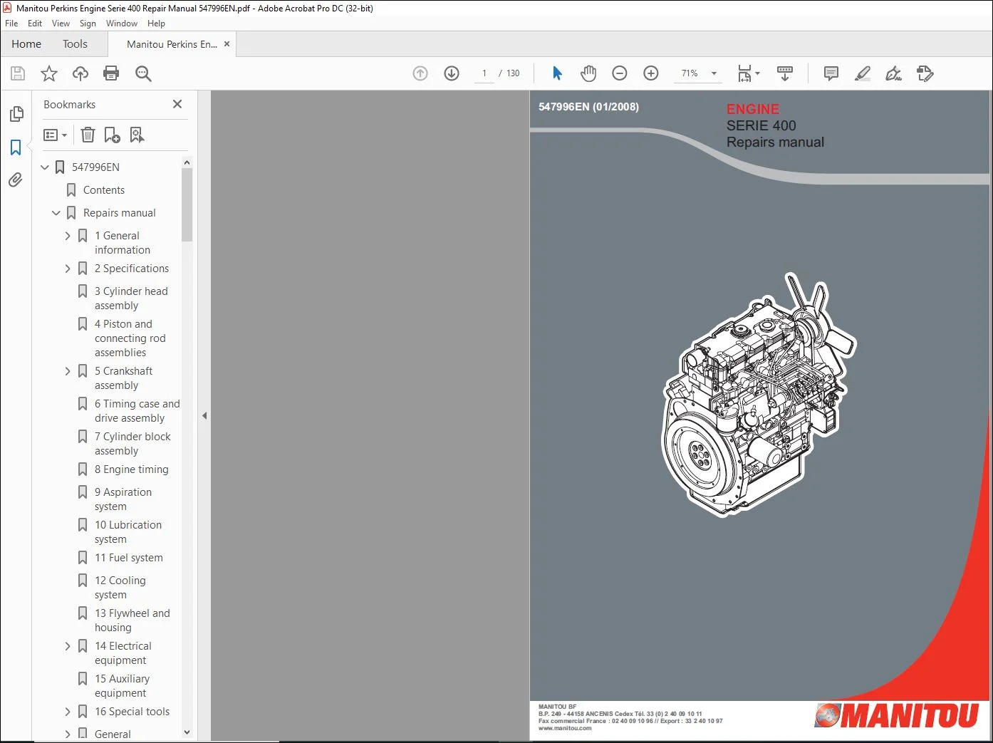
- This workshop manual has been written to provide assistance for technicians who service and overhaul the
Perkins 403C-11, 403C-15, 404C-22 and the 404C-22T engine. The assumption is made that the engine is
removed from the application. - The engine conforms with USA EPA/CARB and EC emissions legislation for agricultural and industrial
applications. - Where the information applies only to certain engine types, this is indicated in the text.
Special tools are available and listed in chapter 16. POWERPART recommended consumable products are
listed in this chapter. There is a reference to the relevant special tools and consumable products at the
beginning of each operation.
TABLE OF CONTENTS:
Manitou Perkins Engine Serie 400 Repair Manual 547996 – PDF DOWNLOAD
1 General information
2 Specifications
3 Cylinder head assembly
4 Piston and connecting rod assemblies
5 Crankshaft assembly
6 Timing case and drive assembly
7 Cylinder block assembly
8 Engine timing
9 Aspiration system
10 Lubrication system
11 Fuel system
12 Cooling system
13 Flywheel and housing
14 Electrical equipment
15 Auxiliary equipment
16 Special tools
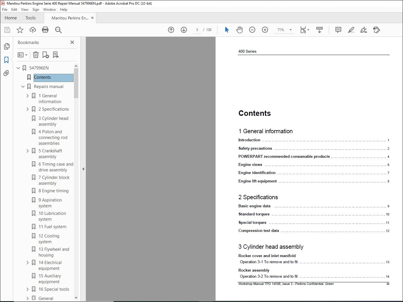
1 General information
Introduction 1
Safety precautions 2
POWERPART recommended consumable products 4
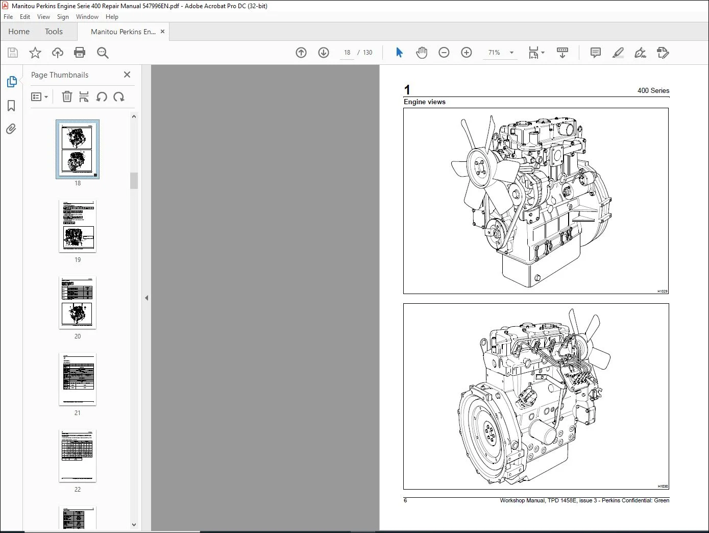
Engine views 6
Engine identification 7
Engine lift equipment 8
2 Specifications
Basic engine data 9
Standard torques 10
Special torques 11
Compression test data 12
3 Cylinder head assembly
Rocker cover and inlet manifold
Operation 3-1 To remove and to fit 13
Rocker assembly
Operation 3-2 To remove and to fit 14
iv Workshop Manual TPD 1458E, issue 3 – Perkins Confidential: Green
400 Series
Operation 3-3 To dismantle and to assemble 15
Operation 3-4 To inspect 16
Exhaust manifold and gasket
Operation 3-5 To remove and to fit 17
Fuel injection pipes / fuel return pipes
Operation 3-6 To remove and to fit 18
Cylinder head setscrews
Operation 3-7 To remove and to fit 19
Cylinder head
Operation 3-8 Tightening sequence 403C-11 and 403C-15 20
Operation 3-9 Tightening sequence 404C-22 and 404C-22T 21
Cylinder head gasket
Operation 3-10 To remove and to fit 22
Operation 3-11 To select the correct thickness of cylinder head gasket 23
Valve and valve spring
Operation 3-12 To remove and to fit 24
Operation 3-13 To inspect – valve spring 25
Operation 3-14 To inspect – valve stem and thickness of valve head 26
Cylinder head to valve stem clearance
Operation 3-15 To inspect 27
Cylinder head
Operation 3-16 To inspect 28
Valve seat width
Operation 3-17 To inspect and to correct 29
Valve depth
Operation 3-18 To check 30
Operation 3-19 To lap the contact face of the valve seat 31
Valve tip clearance
Operation 3-20 To check and to adjust 32
Workshop Manual TPD 1458E, issue 3 – Perkins Confidential: Green v
400 Series
4 Piston and connecting rod assemblies
Big end bearing and cap
Operation 4-1 To remove and to fit 33
Piston and connecting rod
Operation 4-2 To remove and to fit 34
Operation 4-3 To dismantle and to assemble 35
Piston rings
Operation 4-4 To fit 36
Operation 4-5 To measure the piston ring clearance 37
Operation 4-6 To measure the piston ring gap 38
Piston and connecting rod assemblies
Operation 4-7 To dismantle and to assemble 39
Piston and piston ring
Operation 4-8 To inspect 40
Connecting rod
Operation 4-9 To inspect 41
Connecting rod bearing clearance
Operation 4-10 To check 42
Small end bush
Operation 4-11 To remove and to fit 43
5 Crankshaft assembly
Crankshaft pulley
Operation 5-1 To remove and to fit 45
Crankshaft retaining bolts and crankshaft
Operation 5-2 To remove and to fit 46
Crankshaft
Operation 5-3 To inspect for deflection 47
vi Workshop Manual TPD 1458E, issue 3 – Perkins Confidential: Green
400 Series
Main bearings
Operation 5-4 To dismantle and to assemble 49
Bearing holder 50
6 Timing case and drive assembly
Timing cover
Operation 6-1 To remove 51
Operation 6-2 To fit 52
Angleich
Operation 6-3 To remove and to fit 53
Slider
Operation 6-4 To remove and to fit 54
Camshaft retaining plate
Operation 6-5 To remove and to fit 55
Camshaft and tappets
Operation 6-6 To remove and to fit 56
Camshaft assembly
Operation 6-7 To inspect 57
Maximum fuel screw and maximum speed screw
Operation 6-8 Location 58
Front oil seal and PTO cover
Operation 6-9 To remove and to fit 59
Idler gear and oil pump
Operation 6-10 To remove and to fit 60
Idler hub
Operation 6-11 To remove and to fit 61
Gear teeth backlash
Operation 6-12 To check 62
Workshop Manual TPD 1458E, issue 3 – Perkins Confidential: Green vii
400 Series
Oil pump end float
Operation 6-13 To check and adjust 63
Governor springs
Operation 6-14 To inspect 64
7 Cylinder block assembly
Front crankshaft bush
Operation 7-1 To remove and to fit 65
Operation 7-2 To inspect 66
Cylinder block top face
Operation 7-3 To inspect 67
Cylinder bore
Operation 7-4 To inspect 68
8 Engine timing
Operation 8-1 Injection timing 69
Operation 8-2 To check the timing of the fuel injection pump 70
9 Aspiration system
Breather system
Operation 9-1 Closed circuit, naturally aspirated – to clean and to renew 73
Operation 9-2 Closed circuit turbo charged – to clean and to renew 74
Turbocharger
Operation 9-3 To remove and to fit 75
10 Lubrication system
Lubricating oil canister
Operation 10-1 To fit 77
Pressure relief valve
Operation 10-2 To remove and to fit 78
viii Workshop Manual TPD 1458E, issue 3 – Perkins Confidential: Green
400 Series
Lubricating oil sump
Operation 10-3 To remove and to fit 79
Lubricating oil strainer and suction pipe
Operation 10-4 To remove and to fit 80
Lubricating oil pump
Operation 10-5 To remove and to fit 81
Rotor tip clearance
Operation 10-6 To inspect 82
Oil pressure switch
Operation 10-7 To remove and to fit 83
Lubricating oil pipes
Operation 10-8 To remove and to fit 84
11 Fuel system
Atomisers
Operation 11-1 To remove and to fit 85
Fuel lift pump
Operation 11-2 To remove and to fit 87
Fuel injection pump
Operation 11-3 To remove and to fit 88
Operation 11-4 To eliminate air from the fuel system 89
12 Cooling system
Coolant pump
Operation 12-1 To remove and to fit 91
Operation 12-2 To inspect 92
Fan and mounting
Operation 12-3 To remove and to fit 93
Workshop Manual TPD 1458E, issue 3 – Perkins Confidential: Green ix
400 Series
Thermostat
Operation 12-4 To remove and to fit 94
Operation 12-5 To drain the cylinder block 95
Operation 12-6 To test and to inspect 96
13 Flywheel and housing
Flywheel
Operation 13-1 To remove and to fit 97
Operation 13-2 To check for concentricity and alignment of the flywheel housing 98
Operation 13-3 To check for run-out of the flywheel and alignment of the flywheel face 99
Starter ring gear
Operation 13-4 To remove and to fit 100
Backplate and rear oil seal
Operation 13-5 To remove and to fit 101
14 Electrical equipment
Electrical shut off solenoid
Operation 14-1 To remove and to fit 103
Bus-bar / glowplugs
Operation 14-2 To remove and to fit 104
Drive belt
Operation 14-3 To inspect and to adjust 105
Alternator
Operation 14-4 To remove and to fit 106
Starter motor
Operation 14-5 To remove and to fit 107
Wiring diagram 15 amp alternator – 403C-11 108
Wiring diagram 40 amp alternator – 403C-11 109
Wiring diagram 55 amp alternator 403C-15, 404C-22 and 404C-22T 110
Automatic shutdown connector 111
Wiring diagram – automatic shutdown 15 amp alternator – 403C-11 112
x Workshop Manual TPD 1458E, issue 3 – Perkins Confidential: Green
400 Series
Wiring diagram – automatic shutdown 40 amp alternator – 403C-11 113
Wiring diagram – automatic shutdown 55 amp alternator 403C-15, 404C-22
and 404C-22T 114
15 Auxiliary equipment
Operation 15-1 None fitted 115
16 Special tools
Special tools list 117
Need help? Contact: [email protected]
https://vimeo.com/737238510
PLEASE NOTE:
- This is the SAME manual used by the dealers to troubleshoot any faults in your vehicle. This can be yours in 2 minutes after the payment is made.
- Contact us at [email protected] should you have any queries before your purchase or that you need any other service / repair / parts operators manual.
S.V