Manitou Perkins New 1000 Series AJ-AS & YG-YK Workshop Manual – PDF DOWNLOAD
Original price was: $86.95.$29.95Current price is: $29.95.
Manitou Perkins New 1000 Series AJ-AS & YG-YK Workshop Manual – PDF DOWNLOAD
Description
Manitou Perkins New 1000 Series AJ-AS & YG-YK Workshop Manual – PDF DOWNLOAD
IMAGES PREVIEW OF THE MANUAL:
DESCRIPTION:
Manitou Perkins New 1000 Series AJ-AS & YG-YK Workshop Manual – PDF DOWNLOAD
General information :
Introduction:
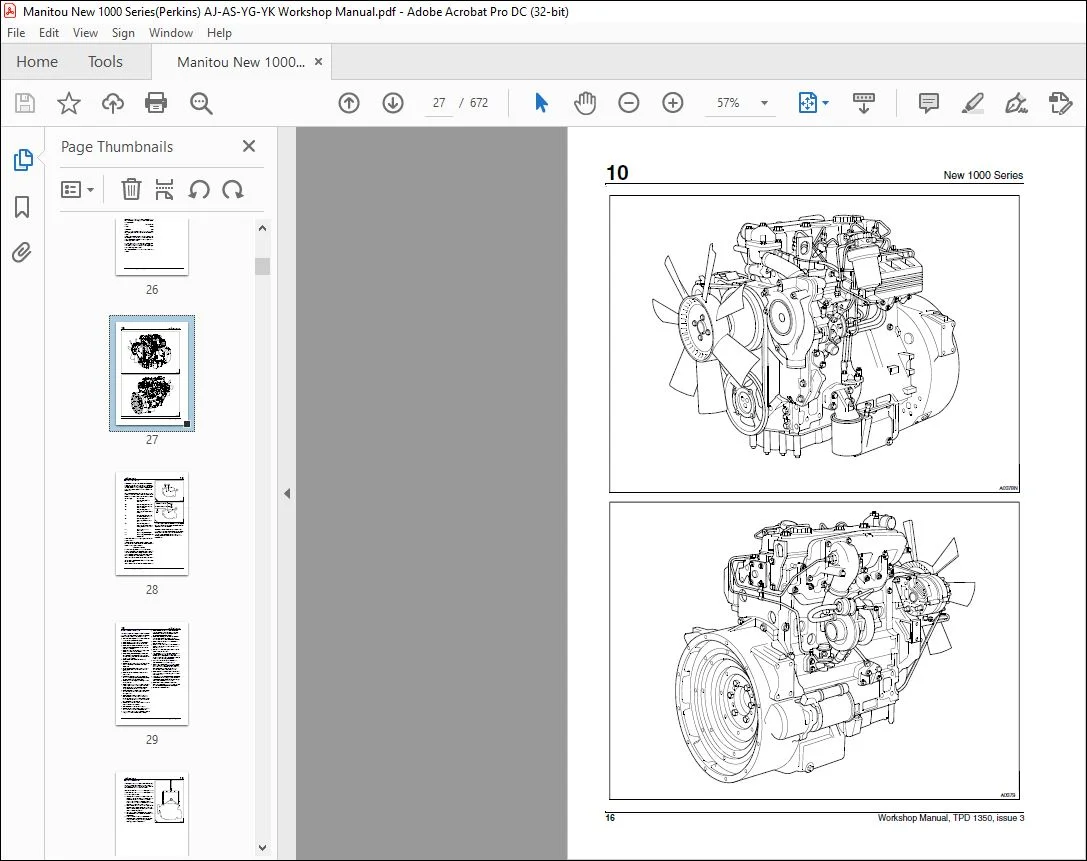
This workshop manual has been written to provide assistance in the service and overhaul of Perkins New 1000 Series engines. For overhaul procedures the assumption is made that the engine is removed from the application.
- The engine conforms with USA (EPA/ CARB) stage 1 and EEC stage 1 emissions legislation for agricultural and industrial applications. Most of the general information which is included in the relevant User’s Handbook (sections 1 to 9) has not been repeated in this workshop manual and the two publications should be used together.
- Where the information applies only to certain engine types, this is indicated in the text. The details of some operations will be different according to the of fuel injection pump which is fitted. The specific pump type used can be found by reference to the manufacturer’s identification plate on the pump body.
TABLE OF CONTENTS:
Manitou Perkins New 1000 Series AJ-AS & YG-YK Workshop Manual – PDF DOWNLOAD
GENERAL INSTRUCTIONS AND SAFETY NOTICE
ENGINE
Group 10 Engine 1
TRANSMISSION
Group 20 GEAR BOX /CONVERTER 311
AXLE ASSEMBLY – AXLE
Group 30 Axle 112 371
Group 30 Pont 212 495
BRAKE
MAST
HYDRAULIC
ELECTRICITY
DRIVER CAB
OPTIONS – ATTACHMENTS
Group 90 OPTIONS – ATTACHMENTS 661
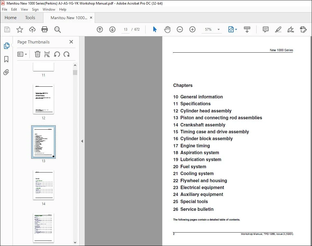
10 General information
11 Specifications
12 Cylinder head assembly
13 Piston and connecting rod assemblies
14 Crankshaft assembly
15 Timing case and drive assembly
16 Cylinder block assembly
17 Engine timing
18 Aspiration system
19 Lubrication system
20 Fuel system
21 Cooling system
22 Flywheel and housing
23 Electrical equipment
24 Auxiliary equipment
25 Special tools
26 Service bulletin
10 General information
Introduction 15
Engine identification 17
General safety precautions 18
Engine lift equipment 19
Viton seals 20
POWERPART recommended consumable products 21
11 Specifications
Basic engine data 23
Thread sealant 24
Standard torque tensions 25
Specific torque tensions 26
Compression test data 29
4 Workshop Manual, TPD 1350, issue 3
New 1000 Series
12 Cylinder head assembly
General description 31
Rocker cover
12-1 To remove and to fit 32
Rocker assembly
12-2 To remove and to fit 33
12-3 To dismantle and to assemble 34
12-4 To inspect and to correct 34
Valve tip clearances
12-5 To check and to adjust 35
Valve springs
12-6 To change the valve springs (with cylinder head fitted) 37
Cylinder head assembly
12-7 To remove and to fit 39
Valves and valve springs
12-8 To remove and to fit 49
12-9 To inspect and to correct 50
Valve guides
12-10 To inspect 51
12-11To remove and to fit 52
Cylinder head
12-12 To inspect and to correct 54
12-13 To correct a valve seat with a valve seat cutter 55
12-14 To fit valve seat inserts 56
Data and dimensions 57
Workshop Manual, TPD 1350, issue 3 5
New 1000 Series
13 Piston and connecting rod assemblies
General description 63
Big end bearing
13-1 To remove and to fit 65
13-2 To inspect 66
Piston and connecting rod
13-3 To remove and to fit 67
13-4 To check the piston height above the cylinder block 70
Piston rings
13-5 To remove and to fit 71
Piston and connecting rod assembly
13-6 To dismantle and to assemble 72
13-7 To check the length of a connecting rod 73
Piston and piston rings
13-8 To inspect 74
Connecting rod
13-9 To inspect 75
Partially finished small end bush
13-10 To remove and to fit 75
Piston cooling jets
13-11 To remove and to fit 76
13-12 To check the jet alignment 76
Data and dimensions 77
6 Workshop Manual, TPD 1350, issue 3
New 1000 Series
14 Crankshaft assembly
General description 79
Crankshaft pulley
14-1 To remove and to fit – four cylinder engines 80
Crankshaft pulley and damper
14-2 To remove and to fit – six cylinder engines 81
14-3 To inspect 83
Rear oil seal assembly
14-4 To remove and to fit 84
14-5 To renew the rear oil seal 85
Thrust washers
14-6 To check crankshaft end-float 86
14-7 To remove and to fit 87
Main bearings
14-8 To remove and to fit (with the crankshaft in position) 89
14-9 To inspect 90
Crankshaft
14-10 To remove and to fit 91
14-11 To inspect 94
Balancer unit
14-12 To remove and to fit 95
14-13 To dismantle and to assemble 96
14-14 To inspect 101
14-15 To remove and to fit the needle roller bearings for the drive shaft 102
14-16 To remove and to fit the bushes for the balance weights 103
Data and dimensions 104
Workshop Manual, TPD 1350, issue 3 7
New 1000 Series
15 Timing case and drive assembly
General description 109
Timing case cover
15-1 To remove and to fit 110
Front oil seal
15-2 To remove and to fit 111
15-3 To fit wear sleeve 112
Idler gear and hub
15-4 To remove and to fit 113
Idler gear and hub for the Bendix compressor
15-5 To remove and to fit 116
Fuel pump gear
15-6 To remove and to fit 118
Camshaft gear
15-7 To remove and to fit 120
Crankshaft gear
15-8 To remove and to fit 121
Timing case
15-9 To remove and to fit 122
Camshaft and tappets
15-10 To remove and to fit 124
Data and dimensions 125
8 Workshop Manual, TPD 1350, issue 3
New 1000 Series
16 Cylinder block assembly
General description 127
Cylinder block
16-1 To dismantle and to assemble 128
16-2 To inspect 129
Cylinder liner
16-3 To inspect 130
16-4 To remove and to fit 131
Cylinder bore, engine types AR and AS
16-5 To inspect 136
Data and dimensions 137
17 Engine timing
General description 141
Engine timing
17-1 To set number 1 piston to TDC on the compression stroke 143
17-2 Another method to set number 1 piston to TDC on the compression stroke 144
17-3 To check the valve timing 144
17-4 To check the timing of the fuel injection pump 145
Data and dimensions 146
18 Aspiration system
General description 147
Turbocharger
18-1 To remove and to fit 149
18-2 To clean the impeller and the compressor casing 151
18-3 To remove and to fit the actuator assembly of the waste-gate unit 152
18-4 To check and adjust the operation of the waste-gate 153
Turbocharger faults 154
Engine breather
18-5 To clean and to renew 156
18-6 To clean and to renew 157
Workshop Manual, TPD 1350, issue 3 9
New 1000 Series
Data and dimensions 158
19 Lubrication system
General description 159
Filter canister
19-1 To renew 163
Filter head
19-2 To remove and to fit 164
Sump
19-3 To remove and to fit 165
Oil strainer and suction pipe
19-4 To remove and to fit 165
16-5 To inspect and to correct 166
Lubricating oil pump
19-6 To remove and to fit 167
19-7 To renew the shaft for the idler gear 169
19-8 To inspect 173
Relief valve
19-9 To remove and to fit 174
19-10 To dismantle and to assemble 175
19-11 To inspect 175
Flexible oil pipes
19-12 To remove, to fit and to inspect 176
Data and dimensions 178
10 Workshop Manual, TPD 1350, issue 3
New 1000 Series
Fuel system
General description 181
Cold start advance unit 183
Typical fuel system 186
Fuel filters 187
Fuel filter element
20-1 To renew 188
Atomisers
20-2 Atomiser fault 191
20-3 To remove and to fit 191
Fuel lift pump
20-4 To remove and to fit 193
20-5 To dismantle and to assemble 194
20-6 To test 195
Bosch fuel injection pump
20-7 To remove and to fit 196
20-8 To adjust 200
20-9 To eliminate air from the fuel system 201
Lucas DP 200 Series fuel injection pump
20-10 To remove to fit 203
20-11 To adjust 207
20-12 To eliminate air from the fuel system Lucas DP200 pump 208
Stanadyne fuel injection pump
20-13 To remove to fit 210
20-14 To adjust 214
20-15 To eliminate air from the fuel system 215
Data and dimensions 217
Workshop Manual, TPD 1350, issue 3 11
New 1000 Series
21 Cooling system
General description 219
Thermostats
21-1 To remove, to fit and to test 220
Coolant pump – early gear driven pumps
21-2 To remove and to fit 221
Coolant pump – latest gear driven pumps
21-3 To remove and to fit 222
Coolant pump – belt driven
21-4 To remove and to fit 224
Coolant pump – belt driven high position
21- 5 To remove and to fit 226
Coolant pump – early gear driven pumps
21-6 To dismantle and to assemble 229
Coolant pump – latest gear driven pumps
21-7 To dismantle and to assemble 232
Coolant pump – belt driven
21-8 To dismantle and to assemble 237
Fan
21-9 To remove and to fit 240
Fan drive (engines with gear driven coolant pumps)
21-10 To remove and to fit 240
Lubricating oil cooler
21-11 To remove and to fit – four cylinder turbocharged engines 241
21-12 To remove and to fit – six cylinder engines 242
21-13 To remove and to fit – pressed steel cover type 243
21-14 To remove and to fit – canister type 245
21-15 To dismantle and to assemble – four cylinder turbocharged engines 246
21-16 To dismantle and to assemble – six cylinder turbocharged engines 247
Cooler by-pass valve
21-17 To remove and to fit 247
21-18 To dismantle and to assemble pressed steel cooler type 248
12 Workshop Manual, TPD 1350, issue 3
New 1000 Series
Intercooler
21-19 To remove and to fit 250
21-20 To clean and to inspect 254
Data and dimensions 255
22 Flywheel and housing
General description 257
Flywheel
22-1 To remove and to fit 258
Ring gear
22-2 To remove and to fit 258
Flywheel housing
22-3 To remove and to fit 259
Data and dimensions 260
Workshop Manual, TPD 1350, issue 3 13
New 1000 Series
23 Electrical equipment
Alternators
General description 261
Precautions 261
Drive belts
23-1 To check 262
23-2 To adjust tension 262
23-3 To remove and to fit 262
Alternator
23-4 To remove and to fit 263
23-5 To maintain 263
Fault diagnosis
Data and dimensions 266
Starter motors
General description 267
Starter motor
23-6 To remove and to fit 268
23-7 To maintain the brush gear and the commutator 269
23-8 To test on the engine 269
Data and dimensions 270
Starting aid
General description 271
Starting aid 271
23-9 To remove and to fit a fuelled starting aid 271
23-10 To remove and to fit a port heater 273
Data and dimensions 274
14 Workshop Manual, TPD 1350, issue 3
New 1000 Series
24 Auxiliary equipment
Compressors
General description 275
Operation 275
Bendix Compressors
24-1 To remove and to fit 276
Data and dimensions 279
Power steering pump
24-2 To remove and to fit 280
Adaptor for a hydraulic pump or a steering pump with a splined drive
24-3 To remove and to fit 281
24-4 To dismantle and to assemble 281
Exhauster
24-5 To remove and to fit 283
25 Special tools
List of special tools 286
Contact us: [email protected]
PLEASE NOTE:
- This is the SAME MANUAL used by the dealerships to diagnose your vehicle
- No waiting for couriers / posts as this is a PDF manual and you can download it within 2 minutes time once you make the payment.
- Your payment is all safe and the delivery of the manual is INSTANT – You will be taken to the DOWNLOAD PAGE.
- So have no hesitations whatsoever and write to us about any queries you may have : heydownloadss @gmail.com
S.V