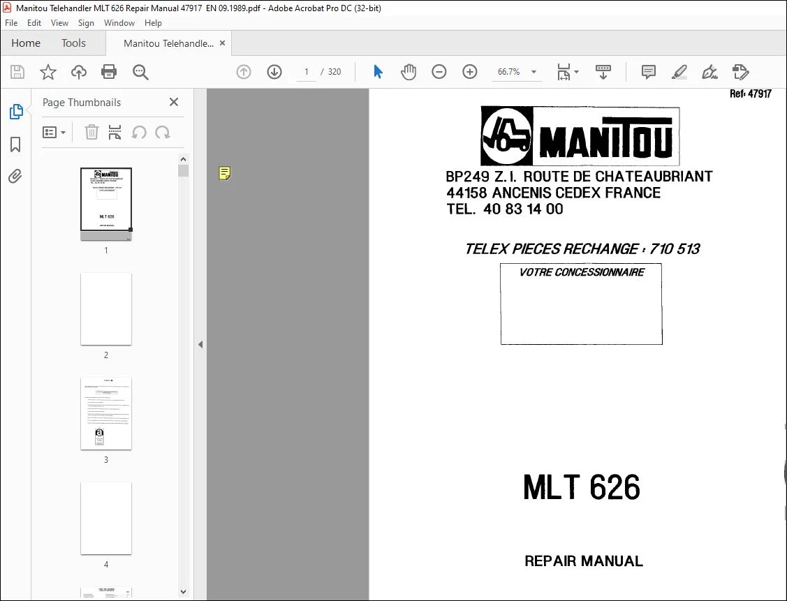
Manitou Telehandler MLT 626 Repair Manual 47917 – PDF DOWNLOAD
Original price was: $86.95.$28.95Current price is: $28.95.
Manitou Telehandler MLT 626 Repair Manual 47917 – PDF DOWNLOAD
Description
Manitou Telehandler MLT 626 Repair Manual 47917 – PDF DOWNLOAD
FILE DETAILS:
Manitou Telehandler MLT 626 Repair Manual 47917 – PDF DOWNLOAD
Language : English
Pages : 320
Downloadable : Yes
File Type : PDF
Size: 8.53 MB
IMAGES PREVIEW OF THE MANUAL:
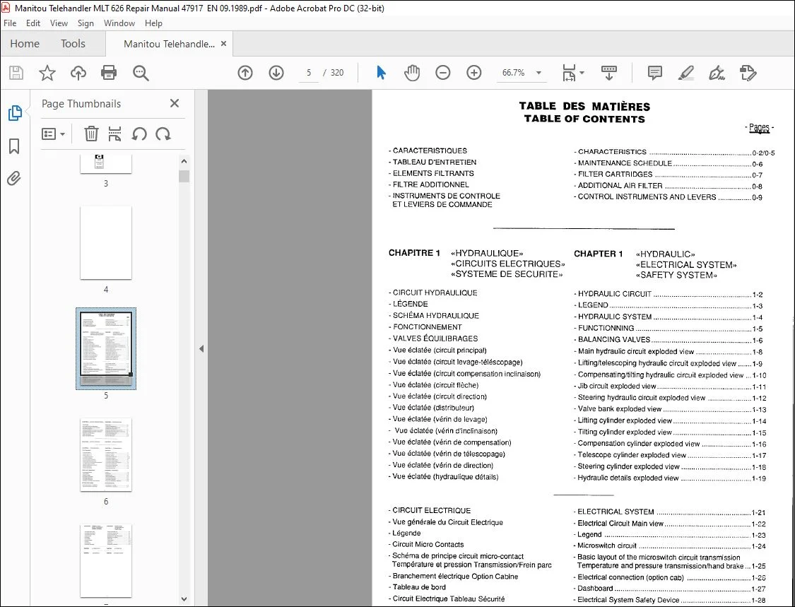
TABLE OF CONTENTS:
Manitou Telehandler MLT 626 Repair Manual 47917 – PDF DOWNLOAD
– CHARACTERISTICS 0-2/0-5
-TABLEAU D’ENTRETIEN – MAINTENANCE SCHEDULE 0-6
– ELEMENTS FILTRANTS – FILTER CARTRIDGES 0-7
– FIL TAE ADDITIONNEL – ADDITIONAL AIR FIL TEA 0-8
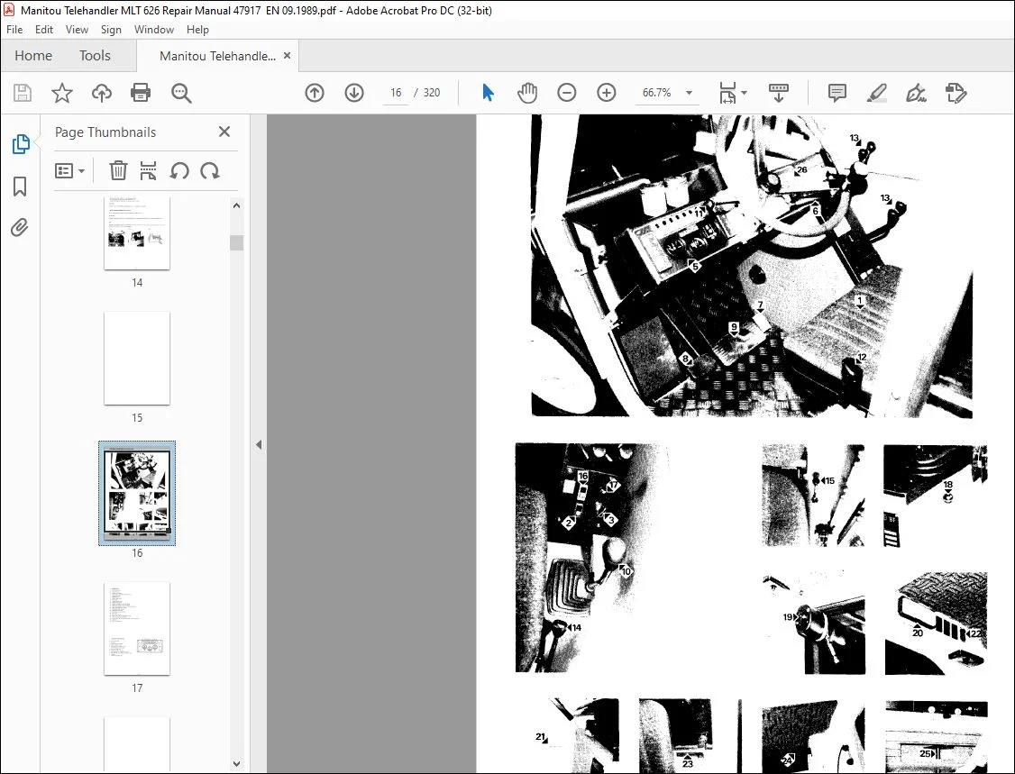
– INSTRUMENTS DE CONTROLE – CONTROL INSTRUMENTS AND LEVERS 0-9
ET LEVIERS DE COMMANDE
CHAPITRE 1 «HYDRAULIOUE» CHAPTER 1 «HYDRAULIC»
«ELECTRICAL SYSTEM»
«SAFETY SYSTEM»
«CIRCUITS ELECTRIQUES»
«SYSTEME DE SECURITE»
– CIRCUIT HYDRAULIQUE – HYDRAULIC CIRCUIT 1-2
– LEGENDE – LEGEND 1-3
– SCHEMA HYDRAULIQUE – HYDRAULIC SYSTEM 1-4
– FONCTIONNEMENT – FUNCTIONNING 1-5
-VALVES EOUILIBRAGES – BALANCING VALVES 1-6
– Vue eclatee (circuit principal) – Main hydraulic circuit exploded view 1-8
– Vue eclatee (circuit levage-telescopage) – Lifting/telescoping hydraulic circuit exploded view 1-9
– Vue eclatee (circuit compensation inclinaison) – Compensating/tilting hydraulic circuit exploded view 1-1 O
– Vue eclatee (circuit fleche) – Jib circuit exploded view 1-11
– Vue eclatee (circuit direction) – Steering hydraulic circuit exploded view 1-12
– Vue eclatee (distributeur) – Valve bank exploded view 1-13
– Vue eclatee (verin de levage) – Lifting cylinder exploded view 1-14
– Vue eclatee (verin d’inclinaison) – Tilting cylinder exploded view 1 · 15
– Vue eclatee (verin de compensation) – Compensation cylinder exploded view 1-16
– Vue eclatee (verin de telescopage) – Telescope cylinder exploded view 1-17
– Vue eclatee (verin de direction) – Steering cylinder exploded view 1-18
– Vue eclatee (hydraulique details) – Hydraulic details exploded view 1-19
– CIRCUIT ELECTRIQUE – ELECTRICAL SYSTEM 1-21
– Vue generale du Circuit Electrique – Electrical Circuit Main view 1-22
– Legende – Legend 1-23
– Circuit Micro Contacts – Microswitch circuit 1-24
– Schema de principe circuit micro-contact – Basic layout of the microswitch circuit transmission
Temperature et pression Transmission/Frein pare Temperature and pressure transmission/hand brake 1-25
– Branchement electrique Option Cabine – Electrical connection (option cab) 1-25
– Tableau de bord – Dashboard 1-27
– Circuit Electrique Tableau Securite – Electrical System Safety Device 1-28
– Schema de principe du systeme de securite – Basic layout of the safety system 1-29
– Notice de fonctionnement et reglage du systeme
de securite
– Safety system (operation and adjustment)
······················································································· 1-31
– Tableau de contr6Ie du dispositif de securite – Control board of the safety device 1-33
– Vue en coupe du systeme de securite – Safety system section view 1-34
– Reglage du systeme de securite – Operation and adjustement of the safety system 1-35
T1
CHAPITRE 2 «FLECHE TELESCOPIQUE» CHAPTER 2 «TELESCOPIC JIB»
– Vue en coupe – Section view 2-2
– Vue eclatee de la fleche telescopique – Telecopic jib exploded view 2-3
– Changement flexibles du verin d’inclinaison – Replacement of tilting cylinder hoses
et du circuit accessoires and attachments circuit hoses 2-4
– Changement flexibles intermediaires dans la fleche – Replacement intermediary hoses in the jib 2-6
– Changement flexibles de la fleche au distributeur – Replacement hoses from the jib to the valve-bank 2-7
– Depose verin de telescopage – Removal telescoping cylinder 2-8
– Depose du telescope – Removal of the telescope 2-10
– Depose de !’ensemble fleche – Removal of the jib assy 2-12
CHAPITRE 3 «MOTEUR PERKINS» CHAPTER 3 «PERKINS ENGINE»
CHAPITRE 4 «TRANSMISSION» CHAPTER 4 «TRANSMISSION»
FONCTIONNEMENT OPERATION
– Coupe transmission – Transmission sectional view 4-1
– Ligne de force M – AV – Power line – Forward 4-2
– Ligne de force M – AR – Power line – Reverse 4-3
– Vue eclatee transmission – Transmission exploded view 4-4/4-6
– Description transmission – Transmission description 4-5/4-7
– Circuit hydraulique transmission – Transmission hydraulic circuit 4-8
– Schema hydraulique transmission – Transmission hydraulic diagram 4-9
– Fonctionnement circuit hydraulique transmission – Transmission hydraulic circuit operation 4-10
– Vue eclatee valve de controle – Control valve exploded view 4-11
– Reperage orifices valve de contr6Ie – Control valve port identification 4-12
– Entretien transmission – Transmission maintenance 4-15
– Contr6Ie des pressions – Checking the pressures 4-,16
DEMONTAGE/REMONTAGE DISASSEMBLY/ REASSEMBLY
– Informations generales – General 4-18
– Outils speciaux – Special tools 4-19
– Couple de serrage – Tightening torque 4-20
– Specifications techniques – Technical specifications 4-21
– De montage transmission – Transmission disassembly 4-22
– Remontage transmission – Transmission reassembly 4-39
– Demontage I re montage valve de contr6Ie – Control valve disassembly I reassembly 4-45
RECHERCHE DE PANNES TROUBLE SHOOTING
– Recherche de pannes – hydrauliques – Troubleshooting – hydraulic 4-48
– Recherche de pannes – mecaniques – Troubleshooting – mechanical 4-52
T2
CHAPITRE 5 «ESSIEU AVANT»
«BOITE TRANSFERT»
«ESSIEU ARRIERE»
– Vue eclatee essieu avant
– Vue eclatee boite transfert
– Vue eclatee essieu arriere
– Purge des !reins
– Specification
– Vue en coupe
– Couple de serrage
– Graissage
– Outils speciaux
– Demontage, remontage
CHAPITRE 6 ALTERNATE UR
CHAPITRE7 DEMARREUR
CHAPTER 5 «FRONT AXLE»
«TRANSFER BOX»
11REAR AXLE,,
– Front axle exploded view 5-1
– Transfer box exploded view 5-2
– Rear axle exploded view 5-3
– Bleeding the ML T 626 braking system 5-4
– Specification and features 5-8
– Section view 5-11
– Torque settings 5-13
– Lubrication 5-14
– Special tools 5-15
– Disassembly, reassembly 5-24
CHAPTER 6 ALTERNATOR
CHAPTER 7 STARTER MOTOR
T3
Questions? Email us: [email protected]
PLEASE NOTE:
- This is the SAME exact manual used by your dealers to fix your vehicle.
- The same can be yours in the next 2-3 mins as you will be directed to the download page immediately after paying for the manual.
- Any queries / doubts regarding your purchase, please feel free to contact [email protected]
S.V