Manitou Telehandler MLT 630, MLT 730 105D 115D ST4 S2 S1 Repair Manual 647699EN – PDF DOWNLOAD
Original price was: $86.95.$28.95Current price is: $28.95.
Manitou Telehandler MLT 630, MLT 730 105D 115D ST4 S2 S1 Repair Manual 647699EN – PDF DOWNLOAD
647699EN (22/05/2019)
MLT 630 105D ST4 S2
MLT 630 105D V ST4 S2
MLT 630 105D V CP ST4 S2
MLT 730 115D V ST4 S1
MLT 730 115D V CP ST4 S1
Description
Manitou Telehandler MLT 630, MLT 730 105D 115D ST4 S2 S1 Repair Manual 647699EN – PDF DOWNLOAD
FILE DETAILS:
Manitou Telehandler MLT 630, MLT 730 105D 115D ST4 S2 S1 Repair Manual 647699EN – PDF DOWNLOAD
Language : English
Pages : 357
Downloadable : Yes
File Type : PDF
Size: 55.7 MB
IMAGES PREVIEW OF THE MANUAL:
Contact us: [email protected]
https://vimeo.com/777553816
DESCRIPTION:
Manitou Telehandler MLT 630, MLT 730 105D 115D ST4 S2 S1 Repair Manual 647699EN – PDF DOWNLOAD
647699EN (22/05/2019)
MLT 630 105D ST4 S2
MLT 630 105D V ST4 S2
MLT 630 105D V CP ST4 S2
MLT 730 115D V ST4 S1
MLT 730 115D V CP ST4 S1
GENERAL INSTRUCTIONS AND SAFETY NOTICE
00.1.1 INTRODUCTION
This chapter deals with the general instructions and safety notice during inspection and maintenance
work.
Other instructions and warnings are indicated in each chapter concerned.
In order to reduce accident risks, make sure to:
– Follow the instructions in the truck operating and maintenance manual.
⇒ This manual should be found in all trucks.
– Please follow all safety instructions.
– Use the appropriate tools for any work to be performed.
– Use original Manitou spare parts.
Any non-compliance increases the risk of accidents occurring which may lead to causing grievous bodily
harm and even death.
An effi cient, dependable and profi table combination will be formed if the operator follows the safety
manual correctly and the machine is serviced properly.
TABLE OF CONTENTS:
Manitou Telehandler MLT 630, MLT 730 105D 115D ST4 S2 S1 Repair Manual 647699EN – PDF DOWNLOAD
647699EN (22/05/2019) – MLT 630 105D ST4 S2 – MLT 630 105D V ST4 S2 – MLT 630 105D V CP ST4 S2 – MLT 730 115D V ST4 S1 – MLT 730 115D V CP ST4 S1 – REPAIR MANUAL …. 1
Sommaire général – General table of content…………………………………………………………………………………………………………… 3
00……………………………………………………………………………………………………………………………………………….. 9
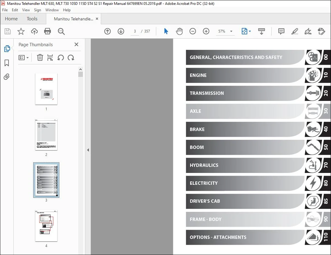
GENERAL, CHARACTERISTICS AND SAFETY………………………………………………………………………………………………………………….. 10
00.1 GENERAL INSTRUCTIONS AND SAFETY NOTICE……………………………………………………………………………………………………….. 10
00.1.1 INTRODUCTION…………………………………………………………………………………………………………………………. 10
00.1.2 SERVICING POSITION……………………………………………………………………………………………………………………. 10
00.1.3 EXPLANATION OF SYMBOLS………………………………………………………………………………………………………………… 11
00.1.4 SERVICING RULES………………………………………………………………………………………………………………………. 12
00.2 GENERAL CHARACTERISTICS AND SPECIFICATIONS……………………………………………………………………………………………………. 15
00.2.1 CHARACTERISTICS………………………………………………………………………………………………………………………. 15
00.2.2 LUBRICANTS AND FUEL…………………………………………………………………………………………………………………… 15
00.2.3 DIMENSIONS…………………………………………………………………………………………………………………………… 16
00.3 GENERAL LOCATION…………………………………………………………………………………………………………………………… 17
00.3.1 LOCATION OF NAME AND IDENTIFICATION PLATE……………………………………………………………………………………………….. 17
00.4 GENERAL CONTROL AND ADJUSTMENT………………………………………………………………………………………………………………. 18
00.4.1 STANDARD TIGHTENING TORQUES……………………………………………………………………………………………………………. 18
00.4.2 METRIC – IMPERIAL UNIT CONVERSION………………………………………………………………………………………………………. 19
10……………………………………………………………………………………………………………………………………………….. 21
ENGINE……………………………………………………………………………………………………………………………………………. 23
10.1 Engine characteristics and specifications…………………………………………………………………………………………………….. 23
10.1.1 Characteristics………………………………………………………………………………………………………………………. 23
10.1.2 Diesel exhaust fluid (DEF)…………………………………………………………………………………………………………….. 23
Characteristics…………………………………………………………………………………………………………………………. 23
Levels…………………………………………………………………………………………………………………………………. 23
Wintering………………………………………………………………………………………………………………………………. 23
10.1.3 Injection cycle………………………………………………………………………………………………………………………. 24
Effects of fuel pre-injection…………………………………………………………………………………………………………….. 24
Effects of fuel post-injection……………………………………………………………………………………………………………. 24
10.1.4 Bosch CP4.1 high pressure pump…………………………………………………………………………………………………………. 25
10.2 Engine Schematic Diagrams…………………………………………………………………………………………………………………… 26
10.2.1 Intake circuit and EGR………………………………………………………………………………………………………………… 26
10.2.2 Lubrication circuit…………………………………………………………………………………………………………………… 27
10.2.3 Cooling circuit………………………………………………………………………………………………………………………. 28
10.2.4 Fuel circuit…………………………………………………………………………………………………………………………. 29
10.2.5 DEF (Diesel Exhaust Fluid) circuit……………………………………………………………………………………………………… 30
10.3 Engine components location………………………………………………………………………………………………………………….. 31
10.3.1 Engine components…………………………………………………………………………………………………………………….. 31
10.3.2 Water and air cooling circuit………………………………………………………………………………………………………….. 33
10.3.3 Diesel fuel circuit…………………………………………………………………………………………………………………… 34
10.3.4 Fuel injection circuit………………………………………………………………………………………………………………… 35
10.3.5 EGR circuit………………………………………………………………………………………………………………………….. 36
10.3.6 DEF circuit………………………………………………………………………………………………………………………….. 37
10.4 Engine controls and adjustments……………………………………………………………………………………………………………… 38
10.4.1 Engine start-up authorization conditions………………………………………………………………………………………………… 38
10.4.2 DEF regeneration……………………………………………………………………………………………………………………… 38
10.4.3 DEF pump cleaning procedure……………………………………………………………………………………………………………. 39
10.4.4 Engine load level…………………………………………………………………………………………………………………….. 43
10.4.5 Fan control………………………………………………………………………………………………………………………….. 44
A – function……………………………………………………………………………………………………………………………. 44
B – principle of operation……………………………………………………………………………………………………………….. 44
C – schematic diagram……………………………………………………………………………………………………………………. 45
D – hydraulic engine description………………………………………………………………………………………………………….. 45
E – conditions of fan control-related components……………………………………………………………………………………………. 46
10.4.6 Orientation of DE suspension silent blocks – mechanical lift truck…………………………………………………………………………. 47
10.4.7 Orientation of DE suspension silent blocks – hydrostatic lift truck………………………………………………………………………… 47
10.4.8 Engine tightening torques……………………………………………………………………………………………………………… 48
10.4.9 Engine suspension tightening torques – mechanical lift truck………………………………………………………………………………. 48
10.4.10 Engine suspension tightening torques – hydrostatic lift truck…………………………………………………………………………….. 49
10.4.11 Diesel fuel circuit tightening torques…………………………………………………………………………………………………. 49
10.4.12 Exhaust and DEF system tightening torques………………………………………………………………………………………………. 50
10.4.13 Cooling system tightening torques……………………………………………………………………………………………………… 51
10.4.14 Heating system tightening torques……………………………………………………………………………………………………… 52
10.5 Engine removal – refitting………………………………………………………………………………………………………………….. 52
10.5.1 Remove the engine ECU…………………………………………………………………………………………………………………. 52
10.5.2 Remove the additional diesel fuel tank………………………………………………………………………………………………….. 52
10.5.3 Remove the DEF tank…………………………………………………………………………………………………………………… 53
10.5.4 Removing the engine cover……………………………………………………………………………………………………………… 54
10.5.5 Remove the expansion tank……………………………………………………………………………………………………………… 54
10.5.6 Remove the SCR……………………………………………………………………………………………………………………….. 55
10.5.7 Remove the mixer tube…………………………………………………………………………………………………………………. 56
Refit………………………………………………………………………………………………………………………………….. 56
10.5.8 Remove the DOC……………………………………………………………………………………………………………………….. 56
10.5.9 Refit the exhaust line………………………………………………………………………………………………………………… 57
10.5.10 Remove the air conditioning compressor…………………………………………………………………………………………………. 57
10.5.11 Remove the engine housing…………………………………………………………………………………………………………….. 57
10.5.12 Remove the engine……………………………………………………………………………………………………………………. 58
10.5.13 Remove the fan motor…………………………………………………………………………………………………………………. 61
Refit………………………………………………………………………………………………………………………………….. 62
10.5.14 Alternator removal…………………………………………………………………………………………………………………… 63
10.5.15 Water pump removal…………………………………………………………………………………………………………………… 63
10.5.16 Turbo-compressor removal……………………………………………………………………………………………………………… 63
10.6 Engine troubleshooting……………………………………………………………………………………………………………………… 63
10.7 Specific engine tooling…………………………………………………………………………………………………………………….. 63
10.7.1 Special engine tooling………………………………………………………………………………………………………………… 63
10.7.2 Electronic tension meter………………………………………………………………………………………………………………. 63
10.7.3 DEF FLUSH KIT………………………………………………………………………………………………………………………… 64
20……………………………………………………………………………………………………………………………………………….. 65
TRANSMISSION………………………………………………………………………………………………………………………………………. 67
20.1 Transmission schematic diagrams……………………………………………………………………………………………………………… 67
20.1.1 MECHANICAL TRANSMISSION compact+ (C+)…………………………………………………………………………………………………… 67
MECHANICAL TRANSMISSION C+ flow diagram……………………………………………………………………………………………………. 67
MECHANICAL TRANSMISSION (C+) operation overview…………………………………………………………………………………………….. 68
20.1.2 HYDROSTATIC TRANSMISSION………………………………………………………………………………………………………………. 69
HYDROSTATIC flow diagram ………………………………………………………………………………………………………………… 69
Hydrostatic operation block diagrams………………………………………………………………………………………………………. 70
20.2 Transmission locations……………………………………………………………………………………………………………………… 71
20.2.1 Mechanical transmission and gear box cooling…………………………………………………………………………………………….. 71
20.2.2 Hydrostatic transmission………………………………………………………………………………………………………………. 72
20.3 Transmission controls and adjustments………………………………………………………………………………………………………… 73
20.3.1 Hydrostatic auto-calibration…………………………………………………………………………………………………………… 73
20.3.2 PRESSURE CONTROL …………………………………………………………………………………………………………………….. 74
Mechanical transmission………………………………………………………………………………………………………………….. 74
Hydrostatic transmission…………………………………………………………………………………………………………………. 74
20.3.3 General authorisation conditions for carriage movement……………………………………………………………………………………. 74
Acquisition conditions…………………………………………………………………………………………………………………… 74
Upkeep conditions……………………………………………………………………………………………………………………….. 74
Loss conditions…………………………………………………………………………………………………………………………. 74
20.3.4 Verification of hydrostatic carriage configurations………………………………………………………………………………………. 74
20.3.5 Eco Mode on hydrostatic carriages………………………………………………………………………………………………………. 74
20.3.6 Adjust the hydrostatic motor sensor…………………………………………………………………………………………………….. 75
Preparation…………………………………………………………………………………………………………………………….. 75
Adjust the sensor……………………………………………………………………………………………………………………….. 75
20.3.7 Mechanical transmission tightening torque……………………………………………………………………………………………….. 78
20.3.8 Hydrostatic transmission tightening torque………………………………………………………………………………………………. 78
20.3.9 Towing procedure……………………………………………………………………………………………………………………… 79
20.4 Transmission removal – refit………………………………………………………………………………………………………………… 79
20.4.1 Remove the engine flywheel damper………………………………………………………………………………………………………. 79
20.4.2 Remove the manual gear box…………………………………………………………………………………………………………….. 79
Refit………………………………………………………………………………………………………………………………….. 80
20.4.3 Remove the angle gear box……………………………………………………………………………………………………………… 80
Refit………………………………………………………………………………………………………………………………….. 81
20.4.4 Remove the hydrostatic pump……………………………………………………………………………………………………………. 81
20.4.5 Remove the hydrostatic motor…………………………………………………………………………………………………………… 82
20.4.6 Remove the transfer box……………………………………………………………………………………………………………….. 83
Refit………………………………………………………………………………………………………………………………….. 85
20.4.7 Take off the gearbox sensors…………………………………………………………………………………………………………… 85
Preparation…………………………………………………………………………………………………………………………….. 85
Take off the gearbox sensors……………………………………………………………………………………………………………… 86
Refit the gearbox sensors………………………………………………………………………………………………………………… 86
20.5 Transmission troubleshooting………………………………………………………………………………………………………………… 87
20.6 Specific transmission tooling……………………………………………………………………………………………………………….. 88
20.6.1 Basic manometer box…………………………………………………………………………………………………………………… 88
20.6.2 Digital manometer box…………………………………………………………………………………………………………………. 89
40……………………………………………………………………………………………………………………………………………….. 91
BRAKE…………………………………………………………………………………………………………………………………………….. 92
40.1 – BRAKE characteristics and specifications……………………………………………………………………………………………………. 92
40.1.1 Brake components characteristics……………………………………………………………………………………………………….. 92
40.1.2 TRAILER BRAKE VALVE…………………………………………………………………………………………………………………… 92
40.2 Brake diagrams…………………………………………………………………………………………………………………………….. 93
40.3 Brake location…………………………………………………………………………………………………………………………….. 93
40.3.1 Hydraulic control…………………………………………………………………………………………………………………….. 93
40.3.2 Mechanical control with sensor…………………………………………………………………………………………………………. 93
Standard tow tractor with cable tension sensor……………………………………………………………………………………………… 94
40.4 Brake control and adjustment………………………………………………………………………………………………………………… 94
40.4.1 Brake valve tightening torque………………………………………………………………………………………………………….. 94
40.4.2 Master valve adjustment and tightening torque……………………………………………………………………………………………. 94
40.4.3 Trailer brake valve tightening torque…………………………………………………………………………………………………… 94
40.4.4 Towing………………………………………………………………………………………………………………………………. 95
40.4.5 Brake valve pressure connector…………………………………………………………………………………………………………. 95
40.4.6 Adjusting the parking brake (Hydrostatic transmission)……………………………………………………………………………………. 95
40.4.7 BRAKE PEDAL ON MLT 630 105 D…………………………………………………………………………………………………………… 96
40.4.8 BRAKE PEDAL ON MLT 630 105D V + CP ST4 S2 / MLT 730 115D V + CP ST4 S1……………………………………………………………………… 97
40.5 Brake removal – refitting…………………………………………………………………………………………………………………… 98
40.5.1 Remove the brake valve………………………………………………………………………………………………………………… 98
Refit………………………………………………………………………………………………………………………………….. 98
50……………………………………………………………………………………………………………………………………………….. 99
BOOM………………………………………………………………………………………………………………………………………………100
50.1 Boom characteristics and specifications……………………………………………………………………………………………………….100
50.1.1 DUPLEX BOOM…………………………………………………………………………………………………………………………..100
50.2 Boom location………………………………………………………………………………………………………………………………101
50.3 Boom control and adjustment………………………………………………………………………………………………………………….101
50.3.1 Mount the boom pads with insert…………………………………………………………………………………………………………101
50.3.2 Secure the pins……………………………………………………………………………………………………………………….101
50.4 Boom removal – refit………………………………………………………………………………………………………………………..101
50.4.1 Remove the telescopic cylinder………………………………………………………………………………………………………….101
70………………………………………………………………………………………………………………………………………………..105
HYDRAULICS…………………………………………………………………………………………………………………………………………106
70.1 Hydraulic characteristics and specifications…………………………………………………………………………………………………..106
70.1.1 Hydraulic component sheets……………………………………………………………………………………………………………..106
BRVI – Reverse ventilation control unit…………………………………………………………………………………………………….106
MV – Master valve (double priority valve)…………………………………………………………………………………………………..110
D – Distributor SDS 140…………………………………………………………………………………………………………………..111
VAF – Brake valve 55 b (MLT 630 MECHANICAL)…………………………………………………………………………………………………113
VAF – Brake valve 80 b (MLT 630/730 V)……………………………………………………………………………………………………..114
70.2 Hydraulic diagrams………………………………………………………………………………………………………………………….115
70.2.1 Keys…………………………………………………………………………………………………………………………………115
70.1.1 Schematic diagrams…………………………………………………………………………………………………………………….116
Flow sharing OPTION………………………………………………………………………………………………………………………116
70.2.2 Diagram – MLT 630 105D ST4 S2…………………………………………………………………………………………………………..117
70.2.3 Diagram – MLT 630 105D V + CP ST4 S2 / MLT 730 115D V + CP ST4 S1…………………………………………………………………………..118
70.3 Hydraulic location………………………………………………………………………………………………………………………….119
70.3.1 General location………………………………………………………………………………………………………………………119
70.3.2 Cooling circuit……………………………………………………………………………………………………………………….119
70.4 Hydraulic control and adjustment……………………………………………………………………………………………………………..120
70.4.1 Accumulator block tightening torque……………………………………………………………………………………………………..120
70.4.2 Distributor tightening torque…………………………………………………………………………………………………………..120
70.4.3 MASTER valve tightening torque………………………………………………………………………………………………………….120
70.4.4 Adjustment of the load valve on the Master valve (Double Priority Valve)…………………………………………………………………….121
70.4.5 Hydraulic pump tightening torque………………………………………………………………………………………………………..121
70.5 Hydraulics removal – refit…………………………………………………………………………………………………………………..122
70.5.1 Remove the hydraulic tank………………………………………………………………………………………………………………122
70.5.2 Remove the hydraulic pump………………………………………………………………………………………………………………123
70.5.3 Control valve removal………………………………………………………………………………………………………………….123
70.6 Hydraulic troubleshooting……………………………………………………………………………………………………………………125
70.6.1 Master valve………………………………………………………………………………………………………………………….125
70.7 Hydraulic specific tooling…………………………………………………………………………………………………………………..127
70.7.1 INFLATION KIT SET……………………………………………………………………………………………………………………..127
70.7.2 BASIC MANOMETER BOX……………………………………………………………………………………………………………………128
70.7.3 DIGITAL MANOMETER BOX………………………………………………………………………………………………………………….129
80………………………………………………………………………………………………………………………………………………..131
Electricity………………………………………………………………………………………………………………………………………..134
80.1 Electricity characteristics and specifications…………………………………………………………………………………………………134
80.1.1 Location of relays and fuses……………………………………………………………………………………………………………134
80.1.2 Screen menus………………………………………………………………………………………………………………………….135
80.1.3 Electrical network architecture…………………………………………………………………………………………………………137
80.1.4 Electrical network architecture details………………………………………………………………………………………………….138
80.1.5 ECU Inputs / Outputs…………………………………………………………………………………………………………………..139
X13 / X25 – SCREEN (A9)…………………………………………………………………………………………………………………..139
X14 – NAVIGATOR (A4)……………………………………………………………………………………………………………………..140
X80 – MAIN ECU SPU 40-26 (A2)……………………………………………………………………………………………………………..141
X81 – MAIN ECU SPU 40-26 (A2)……………………………………………………………………………………………………………..142
X82 – MAIN ECU SPU 40-26 (A2)……………………………………………………………………………………………………………..143
X274 – ENGINE ECU (A2)……………………………………………………………………………………………………………………144
X275 – ENGINE ECU (A2)……………………………………………………………………………………………………………………145
X311 – Transmission ECU V – RC12-10-30 (A10)………………………………………………………………………………………………..146
X312 – Transmission ECU V – rC12-10-30 (A10)………………………………………………………………………………………………..147
X356 – BACK-UP ECU SPU 25-15 (A3)………………………………………………………………………………………………………….148
X357 – BACK-UP ECU SPU 25-15 (A3)………………………………………………………………………………………………………….149
80.1.6 Electricity component sheets……………………………………………………………………………………………………………150
X1/X2 – STARTER IGNITION SWITCH……………………………………………………………………………………………………………150
X10 – LIGHTING COMMUTATOR SWITCH…………………………………………………………………………………………………………..150
X11 / X12 – WIPER STALK…………………………………………………………………………………………………………………..151
X34 – Outside air temperature sensor……………………………………………………………………………………………………….151
X56 – ROTATING BEACON LIGHT……………………………………………………………………………………………………………….152
X74 – ACCELERATOR POTENTIOMETER……………………………………………………………………………………………………………152
X75 / X76 – JSM………………………………………………………………………………………………………………………….153
X77 – BMEP………………………………………………………………………………………………………………………………154
X90 TO X94 – DSB (DOUBLE SWITCH BOARD)……………………………………………………………………………………………………..155
X121 – BRAKE PEDAL ANGLE SENSOR (PS)……………………………………………………………………………………………………….156
X225 – DEF TANK ANALOG GAUGE………………………………………………………………………………………………………………157
X245 – BOOST AIR TEMPERATURE SENSOR………………………………………………………………………………………………………..158
X246 – Oil temperature sensor……………………………………………………………………………………………………………..158
X247 – Hydraulic oil temperature sensor…………………………………………………………………………………………………….159
X252 – VENTILATION CONTROL ELECTROVALVE…………………………………………………………………………………………………….159
X253 – VENTILATION REVERSAL ELECTROVALVE……………………………………………………………………………………………………160
X336 – HYDROSTATIC OIL TEMPERATURE SENSOR ………………………………………………………………………………………………….160
X343 – Main tank FUEL LEVEL SENSOR…………………………………………………………………………………………………………161
X344 – Additional tank FUEL LEVEL SENSOR……………………………………………………………………………………………………161
80.2 Wiring diagrams…………………………………………………………………………………………………………………………….163
80.2.1 MLT 630 105D ST4 S2……………………………………………………………………………………………………………………163
Position by diagram………………………………………………………………………………………………………………………163
Diagram 1 – Starting……………………………………………………………………………………………………………………..169
Diagram 2 – CAN………………………………………………………………………………………………………………………….172
Diagram 3 – Transmission………………………………………………………………………………………………………………….174
Diagram 4 – Hydraulic movements……………………………………………………………………………………………………………176
Diagram 5 – Sensors………………………………………………………………………………………………………………………178
Diagram 6 – Ventilation, wipers and air-conditioning…………………………………………………………………………………………180
Diagram 7 – Automatic air conditioning option……………………………………………………………………………………………….180
Diagram 8 – Options………………………………………………………………………………………………………………………182
Diagram 9 – Lights and signals…………………………………………………………………………………………………………….184
80.2.2 MLT 630 105D V + CP ST4 S2 / MLT 730 115D V + CP ST4 S1……………………………………………………………………………………187
Position by diagram………………………………………………………………………………………………………………………187
Diagram 1 – Starting……………………………………………………………………………………………………………………..193
Diagram 2 – CAN………………………………………………………………………………………………………………………….196
Diagram 3 – Transmission………………………………………………………………………………………………………………….198
Diagram 4 – Hydraulic movements……………………………………………………………………………………………………………200
Diagram 5 – Sensors………………………………………………………………………………………………………………………202
Diagram 6 – Ventilation, wipers and air-conditioning…………………………………………………………………………………………204
Diagram 7 – Automatic air conditioning option……………………………………………………………………………………………….204
Diagram 8 – Options………………………………………………………………………………………………………………………206
Diagram 9 – Lights and signals…………………………………………………………………………………………………………….208
80.3 Electrical location…………………………………………………………………………………………………………………………210
80.3.1 Parts list……………………………………………………………………………………………………………………………210
80.3.2 3D Frame MLT 630 105D V + CP ST4 S2 / MLT 730 115D V + CP ST4 S1……………………………………………………………………………216
80.3.3 3D Frame MLT 630 105D ST4 S2……………………………………………………………………………………………………………217
80.3.4 3D Cab……………………………………………………………………………………………………………………………….218
80.3.5 3D Engine…………………………………………………………………………………………………………………………….219
80.3.6 2D Frame MLT 630 105D V + CP ST4 S2 / MLT 730 115D V + CP ST4 S1……………………………………………………………………………220
80.3.7 2D Frame MLT 630 105D ST4 S2……………………………………………………………………………………………………………221
80.3.8 2D Cab……………………………………………………………………………………………………………………………….222
80.3.9 2D engine…………………………………………………………………………………………………………………………….223
80.3.10 2D Valve Bank………………………………………………………………………………………………………………………..224
80.3.11 2D Diesel Pump……………………………………………………………………………………………………………………….225
80.4 ELECTRICITY REMOVAL-REFIT……………………………………………………………………………………………………………………226
80.4.1 Remove the engine ECU………………………………………………………………………………………………………………….226
80.4.2 Remove the main ECU “SPU 40-26”…………………………………………………………………………………………………………227
80.4.3 Remove the dashboard screen…………………………………………………………………………………………………………….227
80.4.4 Remove – Replace JSM on BMEP……………………………………………………………………………………………………………228
80.4.5 Strain gauge refit…………………………………………………………………………………………………………………….229
Location………………………………………………………………………………………………………………………………..229
Axle preparation…………………………………………………………………………………………………………………………230
Characteristics of products used…………………………………………………………………………………………………………..230
Characteristics of fastening screws………………………………………………………………………………………………………..231
Assembly precautions and tightening torque………………………………………………………………………………………………….231
80.4.6 Adjust the strain gauge………………………………………………………………………………………………………………..234
80.5 Electrical troubleshooting…………………………………………………………………………………………………………………..234
80.5.1 Error codes (DTC)……………………………………………………………………………………………………………………..234
DTC ECU HARMONY screen (X13)………………………………………………………………………………………………………………234
Main ECU DTC SPU 40-26 (X80 – X81 – X82)……………………………………………………………………………………………………235
Engine ECU DTC EDC17CV52 (X274 – X275)……………………………………………………………………………………………………..239
Transmission ECU DTC V+ RC12-10-30 (X311 – X312)…………………………………………………………………………………………….256
Auxiliary ECU DTC SPU 25-15 (X356 – X357)…………………………………………………………………………………………………..287
80.6 Specific electric tooling……………………………………………………………………………………………………………………290
80.6.1 BREAKOUT BOXES………………………………………………………………………………………………………………………..290
80.6.2 Electrovalve adapter…………………………………………………………………………………………………………………..290
80.6.3 DIAGNOSTIC TOOLS………………………………………………………………………………………………………………………291
DIAGNOSTICS CASE…………………………………………………………………………………………………………………………291
CONNECTIONS TO LIFT TRUCK………………………………………………………………………………………………………………..292
ENGINE ADAPTATION KIT…………………………………………………………………………………………………………………….292
85………………………………………………………………………………………………………………………………………………..293
DRIVER’S CAB……………………………………………………………………………………………………………………………………….294
85.1 DRIVER’S CAB CONTROL AND ADJUSTMENT…………………………………………………………………………………………………………..294
85.1.1 TIGHTENING TORQUES…………………………………………………………………………………………………………………….294
CAB SILENT BLOCK…………………………………………………………………………………………………………………………294
AIR CONDITIONING…………………………………………………………………………………………………………………………294
85.2 Driver’s cab removal – refit…………………………………………………………………………………………………………………295
85.2.1 Removing the cabin…………………………………………………………………………………………………………………….295
85.2.2 REMOVING THE WINDSCREEN………………………………………………………………………………………………………………..298
PROCEDURE FOR OPENING THE COMPACT PROTECTIVE GRILLE………………………………………………………………………………………….298
Procedure for opening the standard protective grille…………………………………………………………………………………………299
85.2.3 Cab lower trim removal…………………………………………………………………………………………………………………301
85.2.4 Upper dashboard removal………………………………………………………………………………………………………………..301
85.2.5 Heating block removal………………………………………………………………………………………………………………….303
85.3 Specific cab tooling………………………………………………………………………………………………………………………..304
85.3.1 Cab grill hinge kit …………………………………………………………………………………………………………………..304
110……………………………………………………………………………………………………………………………………………….305
OPTIONS – ATTACHMENTS……………………………………………………………………………………………………………………………….308
110 AIR CONDITIONING OPTION………………………………………………………………………………………………………………………308
110.1 Characteristics and specifications……………………………………………………………………………………………………….308
110.1.1 Description of operation…………………………………………………………………………………………………………..308
110.1.2 Operating principle……………………………………………………………………………………………………………….309
110.1.3 Automatic air conditioning ECU Inputs/Outputs………………………………………………………………………………………..311
110.1.4 Evaporator temperature sensor specifications…………………………………………………………………………………………312
110.2 Locations……………………………………………………………………………………………………………………………..313
110.2.1 Components and tightening torques…………………………………………………………………………………………………..313
110.2.2 HVAC interior components…………………………………………………………………………………………………………..314
110.2.3 HVAC exterior components…………………………………………………………………………………………………………..314
110.2.4 Automatic air conditioning locations………………………………………………………………………………………………..315
Key…………………………………………………………………………………………………………………………………316
110.2.5 Condenser components………………………………………………………………………………………………………………316
110.3 Control and adjustment………………………………………………………………………………………………………………….317
110.3.1 General check points………………………………………………………………………………………………………………317
110.3.2 ASSEMBLY INSTRUCTION………………………………………………………………………………………………………………317
110.3.3 Safety measures for handling the r134a………………………………………………………………………………………………318
110.3.4 Refrigerant fluid load…………………………………………………………………………………………………………….318
110.3.5 Check the evaporator temperature sensor……………………………………………………………………………………………..319
110.4 Removal – refit………………………………………………………………………………………………………………………..321
110.4.1 Compressor belt removal……………………………………………………………………………………………………………321
110.4.2 Compressor belt refit……………………………………………………………………………………………………………..322
110.5 Troubleshooting………………………………………………………………………………………………………………………..323
110.5.1 Temperature faults………………………………………………………………………………………………………………..323
110.5.2 Unusual noise…………………………………………………………………………………………………………………….323
110.5.3 UNPLEASANT SMELL………………………………………………………………………………………………………………….323
110.5.4 X39 (C10) – Automatic air-conditioning error codes (DTC)………………………………………………………………………………324
110.6 Specific tooling……………………………………………………………………………………………………………………….324
110.6.1 Fitting wedge for elastic drive belt………………………………………………………………………………………………..324
110 Intelligent hydraulics OPTION…………………………………………………………………………………………………………………325
110.1 Intelligent hydraulics characteristics and specifications…………………………………………………………………………………..325
110.2 Location of components………………………………………………………………………………………………………………….326
110.2.1 Assembly on 6 or 7 metre boom………………………………………………………………………………………………………326
110.2.2 Assembly on 9 metre boom…………………………………………………………………………………………………………..327
110 Pneumatic trailer braking OPTION………………………………………………………………………………………………………………328
110.1 Characteristics and specifications……………………………………………………………………………………………………….328
110.1.1 Operation………………………………………………………………………………………………………………………..328
110.1.2 Component sheets………………………………………………………………………………………………………………….329
Electrovalve…………………………………………………………………………………………………………………………329
Secondary pressure relief valve………………………………………………………………………………………………………..329
Main pressure relief valve…………………………………………………………………………………………………………….330
Circuit selector……………………………………………………………………………………………………………………..330
Hydraulic trailer control valve………………………………………………………………………………………………………..331
Compressor…………………………………………………………………………………………………………………………..331
Trailer control valve…………………………………………………………………………………………………………………332
110.2 Schematic diagrams……………………………………………………………………………………………………………………..333
110.2.1 Machine off………………………………………………………………………………………………………………………333
110.2.2 Machine on and parking brake applied………………………………………………………………………………………………..334
110.2.3 Machine on unbraked……………………………………………………………………………………………………………….334
110.2.4 Machine on and brake pedal pressed………………………………………………………………………………………………….335
110.2.5 Machine on and parking brake test…………………………………………………………………………………………………..335
110.3 Location………………………………………………………………………………………………………………………………336
110 Optional automatic central greasing……………………………………………………………………………………………………………337
110.1 Characteristics and specifications……………………………………………………………………………………………………….337
110.1.1 The auto greasing system…………………………………………………………………………………………………………..337
110.1.2 The pump…………………………………………………………………………………………………………………………338
Composition of the TriPlus pump unit…………………………………………………………………………………………………..339
X434 – Greasing pump………………………………………………………………………………………………………………….340
110.1.3 Distributors……………………………………………………………………………………………………………………..341
110.1.4 Monitoring/storage of data…………………………………………………………………………………………………………342
110.2 Distributor schematic diagrams…………………………………………………………………………………………………………..342
110.3 Location………………………………………………………………………………………………………………………………343
Key:……………………………………………………………………………………………………………………………………343
110.4 Control and adjustment………………………………………………………………………………………………………………….344
110.4.1 The cab warning light……………………………………………………………………………………………………………..344
110.4.2 The test button…………………………………………………………………………………………………………………..344
110.4.3 System filling and bleeding………………………………………………………………………………………………………..344
110.4.4 Maintenance………………………………………………………………………………………………………………………344
110.4.5 Checks…………………………………………………………………………………………………………………………..344
Tightening torque ……………………………………………………………………………………………………………………345
110.5 Troubleshooting………………………………………………………………………………………………………………………..345
110.5.1 Detect faults…………………………………………………………………………………………………………………….345
110.5.2 Faults table……………………………………………………………………………………………………………………..346
110.5.3 Error codes table…………………………………………………………………………………………………………………347
110 Camera option……………………………………………………………………………………………………………………………….348
110.1 Characteristics and specifications……………………………………………………………………………………………………….348
110.1.1 Front, rear and boom head camera system……………………………………………………………………………………………..348
110.1.2 Operation………………………………………………………………………………………………………………………..348
Component sheets …………………………………………………………………………………………………………………….350
Video source selector box……………………………………………………………………………………………………………..350
Wi-Fi boom head camera………………………………………………………………………………………………………………..351
Wi-Fi box……………………………………………………………………………………………………………………………352
Front or rear camera………………………………………………………………………………………………………………….353
110.2 Location………………………………………………………………………………………………………………………………354
110.3 Control and adjustment………………………………………………………………………………………………………………….355
110.3.1 Dashboard adjustments……………………………………………………………………………………………………………..355
110.3.2 Boom head camera support…………………………………………………………………………………………………………..356
PLEASE NOTE:
- This is the SAME MANUAL used by the dealerships to diagnose your vehicle
- No waiting for couriers / posts as this is a PDF manual and you can download it within 2 minutes time once you make the payment.
- Your payment is all safe and the delivery of the manual is INSTANT – You will be taken to the DOWNLOAD PAGE.
- So have no hesitations whatsoever and write to us about any queries you may have : heydownloadss @gmail.com
S.V