Manitou Telehandler MLT 630, MLT 730 115D ST5 S1V CP Repair Manual 647973EN – PDF DOWNLOAD
Original price was: $86.95.$30.95Current price is: $30.95.
Manitou Telehandler MLT 630, MLT 730 115D ST5 S1V CP Repair Manual 647973EN – PDF DOWNLOAD
MLT 630 115D ST5 S1
MLT 630 115D V ST5 S1
MLT 630 115D V CP ST5 S1
MLT 730 115D V ST5 S1
MLT 730 115D V CP ST5 S1
Description
Manitou Telehandler MLT 630, MLT 730 115D ST5 S1V CP Repair Manual 647973EN – PDF DOWNLOAD
FILE DETAILS:
Manitou Telehandler MLT 630, MLT 730 115D ST5 S1V CP Repair Manual 647973EN – PDF DOWNLOAD
Language : English
Pages : 550
Downloadable : Yes
File Type : PDF
Size: 55.6 MB
IMAGES PREVIEW OF THE MANUAL:
Need help? Contact: [email protected]
https://vimeo.com/777561437
DESCRIPTION:
Manitou Telehandler MLT 630, MLT 730 115D ST5 S1V CP Repair Manual 647973EN – PDF DOWNLOAD
MLT 630 115D ST5 S1
MLT 630 115D V ST5 S1
MLT 630 115D V CP ST5 S1
MLT 730 115D V ST5 S1
MLT 730 115D V CP ST5 S1
distribution, etc., in whole or in part, in any format whatsoever, is prohibited. The diagrams, drawings, images,
comments and indications found in this documentation, and the organization of the document itself, are intellectual
property of MANITOU BF. Any violation of the above is subject to civil and criminal penalties. The logos and visual
identity of the company are property of MANITOU BF and may not be used without express formal authorization. All
rights reserved.
Any reproduction, source code access, decompilation, modification, copy (other than backup copies), correction of
errors, transmission or distribution of any software built into Manitou machines is strictly prohibited.
In the event that the measures above nevertheless prove essential to enable use of the software, in accordance
with its destination, or to obtain the information required for interoperability with other software created
independently, the user should contact Manitou in advance and may, at its sole discretion, take the necessary
measures or give access to only the information strictly necessary for interoperability.
Any breach of these requirements is likely to constitute a counterfeiting offense subject to legal action by Manitou.
Connected Manitou machines are equipped with boxes that collect technical data on the machines (such as geotracking
data or data on component operation). This data, which is organized, processed and enhanced by
algorithms and expertise proprietary to Manitou, constitutes a protected database under Article L.341-1 of the
Intellectual Property Code.
It is strictly forbidden to have access to all or part of this database and to use the data (including in the event of
accidental access) without explicit prior authorization from Manitou. In the event that Manitou authorizes a Manitou
machine user to access all or part of this database, Manitou, as producer of this database, cedes to the user only a
right to personal, non-exclusive, nontransferable use of the database, and only by access to an information
technology platform hosted by a server owned or controlled by Manitou.
TABLE OF CONTENTS:
Manitou Telehandler MLT 630, MLT 730 115D ST5 S1V CP Repair Manual 647973EN – PDF DOWNLOAD
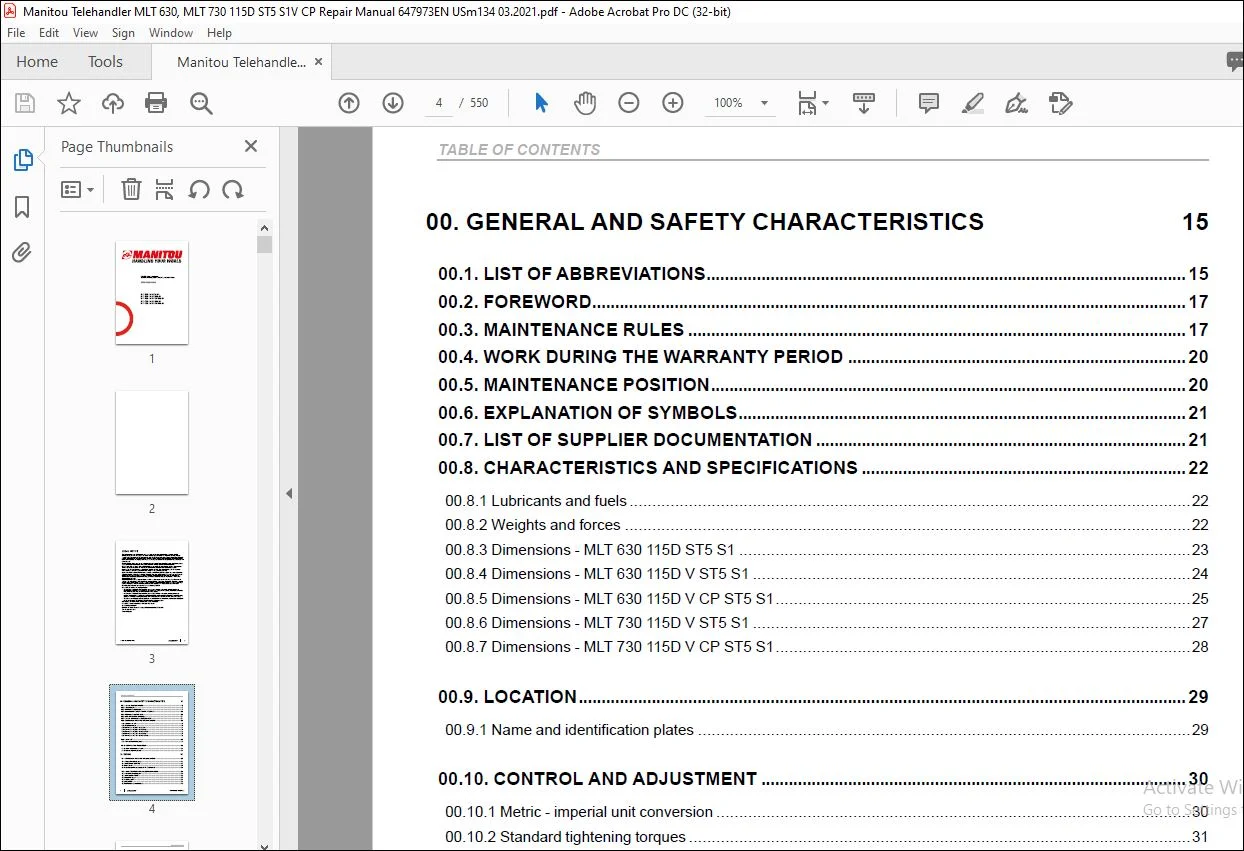
00 GENERAL AND SAFETY CHARACTERISTICS 15
00 1 LIST OF ABBREVIATIONS 15
00 2 FOREWORD 17
00 3 MAINTENANCE RULES 17
00 4 WORK DURING THE WARRANTY PERIOD 20
00 5 MAINTENANCE POSITION 20
00 6 EXPLANATION OF SYMBOLS 21
00 7 LIST OF SUPPLIER DOCUMENTATION 21
00 8 CHARACTERISTICS AND SPECIFICATIONS 22
00 8 1 Lubricants and fuels 22
00 8 2 Weights and forces 22
00 8 3 Dimensions – MLT 630 115D ST5 S1 23
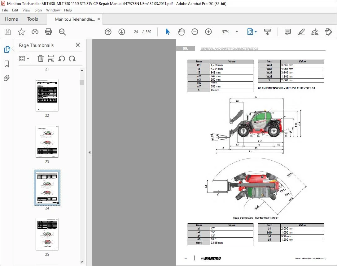
00 8 4 Dimensions – MLT 630 115D V ST5 S1 24
00 8 5 Dimensions – MLT 630 115D V CP ST5 S1 25
00 8 6 Dimensions – MLT 730 115D V ST5 S1 27
00 8 7 Dimensions – MLT 730 115D V CP ST5 S1 28
00 9 LOCATION 29
00 9 1 Name and identification plates 29
00 10 CONTROL AND ADJUSTMENT 30
00 10 1 Metric – imperial unit conversion 30
00 10 2 Standard tightening torques 31
10 ENGINE 33
10 1 CHARACTERISTICS AND SPECIFICATIONS 33
10 1 1 Engine characteristics 115 hp 33
10 1 2 Diesel exhaust fluid (DEF) 33
10 1 3 Fan control 34
10 1 4 Conditions of elements associated with ST5 fan control 34
10 2 FLOW DIAGRAMS AND SCHEMATIC DIAGRAMS 36
10 2 1 Ventilation principle diagram 36
10 2 2 Intake system and EGR 36
10 2 3 Lubrication system 37
10 2 4 Cooling system 38
10 2 5 Fuel system 39
10 2 6 DEF system schematic diagram 40
4 647973EN-USM134(A-03/2021)
TABLE OF CONTENTS
10 2 7 DEF circuit 41
10 3 LOCATION 42
10 3 1 Diesel location system 42
10 3 2 Air intake circuit 44
10 3 3 Exhaust system 45
10 3 4 Water cooling system 46
10 3 5 Engine location 47
10 3 6 Fuel injection circuit 48
10 4 CONTROL AND ADJUSTMENT 49
10 4 1 DEF pump cleaning preparation 49
10 4 2 DEF pump cleaning procedure 49
10 4 3 DEF pump cleaning procedure with the engine diagnostic tool 50
10 4 4 Fan check points 51
10 4 5 Engine load level 51
10 4 6 SCR system bleed time 52
10 4 7 Engine start-up authorization conditions 52
10 4 8 Stationary regeneration authorization conditions 52
10 4 9 Location of exhaust tightening torques 53
10 5 REMOVAL 55
10 5 1 Disconnect the battery 55
10 5 2 Removing the belt casing 55
10 5 3 Remove the air filter 55
10 5 4 Remove the alternator 55
10 5 5 Remove the starter 56
10 5 6 Removing the expansion tank with support 57
10 5 7 Removing the DEF injector 57
10 5 8 Removing the SCR 57
10 5 9 Remove the intermediate tube 58
10 5 10 Remove the DOC-DPF 58
10 5 11 Remove the DOC-DPF converter with support 59
10 5 12 Remove the fan motor 59
10 5 13 Remove the radiator 62
10 5 14 Remove the air conditioning compressor 63
10 5 15 Remove the turbo exhaust outlet tube 63
10 5 16 Removing the turbo 64
10 5 17 Remove the engine 64
10 5 18 Remove the additional fuel tank 67
TABLE OF CONTENTS
647973EN-USM134(A-03/2021) 5
10 6 TROUBLESHOOTING 67
10 6 1 Fault table 67
10 7 SPECIFIC TOOLING 70
10 7 1 DEF flush kit 70
10 7 2 Electronic belt tensiometer 70
20 TRANSMISSION 71
20 1 CHARACTERISTICS AND SPECIFICATIONS 71
20 1 1 Compaq + specifications 71
20 1 2 MPower Box specifications 71
20 1 3 Transfer gearbox characteristics 367 71
20 2 FLOW DIAGRAMS AND SCHEMATIC DIAGRAMS 72
20 2 1 Compact+ (C+) mechanical transmission 72
20 2 2 Hydrostatic transmission diagram 74
20 3 LOCATION 77
20 3 1 Location of mechanical transmission and gearbox cooling 77
20 3 2 Location of Compaq + ports 78
20 3 3 Location of MpowerBox ports 78
20 3 4 Location of hydrostatic transmission 79
20 3 5 Location of ports BT 367 80
20 4 CONTROL AND ADJUSTMENT 80
20 4 1 General authorization conditions for carriage movement 80
20 4 2 Check the machine configurations 80
20 4 3 Hydrostatic auto-calibration 80
20 4 4 ECO Mode on hydrostatic lift truck 81
20 4 5 Adjust the hydrostatic motor sensor 81
20 4 6 Pressure control 83
20 4 7 Checking adjustment of pump A4VG71 series 32 83
20 4 8 Hydrostatic transmission tightening torque 84
20 4 9 Mechanical transmission tightening torque 85
20 4 10 MPower Box tightening torque 85
20 4 11 Towing procedure 86
20 4 12 Free the wheels by removing the universal joints 86
6 647973EN-USM134(A-03/2021)
TABLE OF CONTENTS
20 5 REMOVAL 86
20 5 1 Remove the angle gearbox 86
20 5 2 Remove the manual gearbox 87
20 5 3 Remove the hydrostatic pump 88
20 5 4 Remove the transfer box 89
20 5 5 Remove the hydrostatic motor 91
20 5 6 Remove the engine flywheel damper 92
20 6 TROUBLESHOOTING 92
20 6 1 Transmission troubleshooting 92
20 7 SPECIFIC TOOLING 92
20 7 1 Digital manometer box 92
20 7 2 Basic manometer box 93
30 AXLE 94
30 1 CHARACTERISTICS AND SPECIFICATIONS 94
30 1 1 Characteristics of axle 212 94
30 1 2 Characteristics of axle 212 with service and parking brake 95
30 1 3 Characteristics of axle 212 with service brake 96
30 2 CONTROL AND ADJUSTMENT 96
30 2 1 Check of axle braking discs 96
30 2 2 Axle stop adjustment 96
30 2 3 Axle tightening torques 96
40 BRAKE 97
40 1 CHARACTERISTICS AND SPECIFICATIONS 97
40 1 1 Brake component characteristics 97
40 1 2 Service brake – Specifications of oil bath disc brakes 97
40 1 3 Standard tow tractor with cable tension sensor 98
40 1 4 Trailer pneumatic braking operation 98
40 1 5 Technical sheets for electrical components 99
40 2 FLOW DIAGRAMS AND SCHEMATIC DIAGRAMS 105
40 2 1 Hydraulic diagram of the brakes 105
40 2 2 Schematic diagram of trailer pneumatic braking operation 105
TABLE OF CONTENTS
647973EN-USM134(A-03/2021) 7
40 3 LOCATION 108
40 3 1 Location of the service brake and trailer braking system 108
40 3 2 Location of parking brake components 109
40 3 3 Location of pneumatic braking 110
40 4 CONTROL AND ADJUSTMENT 111
40 4 1 Check of brake disc wear 111
40 4 2 Brake valve tightening torques 111
40 4 3 Settings and tightening torques of the double priority valve 111
40 4 4 Trailer brake valve tightening torques 111
40 4 5 towing procedure 112
40 4 6 Brake valve pressure connector 112
40 4 7 Adjust the parking brake sensor 112
40 4 8 Transmission mechanics MLT 630 113
40 4 9 Hydrostatic transmission (MLT 6/7 V) 115
40 4 10 Bleeding the braking circuit 118
40 5 REMOVAL 119
40 5 1 Remove the brake valve 119
40 6 REFIT 119
40 6 1 Put back the brake valve 119
50 LIFT STRUCTURE 120
50 1 CHARACTERISTICS AND SPECIFICATIONS 120
50 1 1 General characteristics – duplex booms 6 and 7 m 120
50 2 FLOW DIAGRAMS AND SCHEMATIC DIAGRAMS 120
50 2 1 Duplex booms kinematics 6 and 7 m 121
50 3 LOCATION 123
50 3 1 Location of components – duplex boom 6 and 7 m 123
50 4 CONTROL AND ADJUSTMENT 124
50 4 1 Adjust the telescope’s retraction and extension time 124
50 4 2 Adjust the fixed pads using screws and inserts on the duplex boom 124
50 4 3 Chock the boom hinges 125
50 4 4 Duplex boom tightening torques 127
50 4 5 Adjust the limit stop for the single carriage of the duplex boom 129
8 647973EN-USM134(A-03/2021)
TABLE OF CONTENTS
50 5 REMOVAL 130
50 5 1 Prepare for complete boom removal 130
50 5 2 Prepare to remove the internal boom components 130
50 5 3 Remove the telescopic boom cylinder 130
50 5 4 Remove the complete boom 133
50 5 5 Remove the telescope 136
50 6 REFIT 137
50 6 1 Prepare to reinstall the internal boom components 137
50 6 2 Reinstall the telescope 138
50 7 SPECIFIC TOOLING 139
50 7 1 Pipe end pieces 139
70 HYDRAULICS 140
70 1 CHARACTERISTICS AND SPECIFICATIONS 140
70 1 1 List of hydraulic sheets 141
70 1 2 Hydraulic feed block + accumulator 143
70 1 3 Ventilation control unit + inversion PLM20 16 144
70 1 4 4-element hydraulic distributor SDS 140 147
70 1 5 Double priority valve 149
70 1 6 Hydraulic pump KP30 43 150
70 1 7 Dynamic steering pump OSPC 200 151
70 1 8 3/4 position steering distributor 152
70 1 9 Braking valve 55 bar 153
70 1 10 Braking valve 72 bar 155
70 1 11 trailer brake valve 156
70 1 12 Cooling thermostat valve 159
70 2 FLOW DIAGRAMS AND SCHEMATIC DIAGRAMS 160
70 2 1 Hydraulic diagram MLT 630 – 730 161
70 2 2 Hydraulic diagram MLT 630 – 730 V 167
70 3 LOCATION 173
70 3 1 Hydraulic components location – MLT 630 115D ST5 S1 (+ options) 173
70 3 2 Hydraulic components location – MLT 630 115D V ST5 S1 (+ options) 174
70 3 3 Hydraulic components location – MLT 630 115D V CP ST5 S1 (+ options) 176
70 3 4 Hydraulic components location – MLT 730 115D V ST5 S1 (+ options) 177
70 3 5 Hydraulic components location – MLT 730 115D V CP ST5 S1 (+ options) 179
TABLE OF CONTENTS
647973EN-USM134(A-03/2021) 9
70 4 CONTROL AND ADJUSTMENT 180
70 4 1 Purge the air from the hydraulic valve bank 180
70 4 2 Adjust of the load valve on the double priority valve 181
70 4 3 Hydraulic distributor tightening torques 181
70 4 4 Tightening torques of the double priority valve 182
70 4 5 Tightening torques of the hydraulic pump 182
70 4 6 Tightening torques of the hydraulic fluid tank 182
70 4 7 Tightening torque of the fan control bloc + inversion 183
70 4 8 Tightening torque of the cooling thermostat valve (hydrostatic versions only) 183
70 5 REMOVAL 183
70 5 1 Preparing and securing the machine before removal of hydraulic components 183
70 5 2 Remove the hydraulic fluid tank 184
70 5 3 Remove the hydraulic pump 185
70 5 4 Remove the hydraulic distributor 185
70 6 TROUBLESHOOTING 186
70 6 1 Troubleshooting on the double priority / master valve 186
70 7 SPECIFIC TOOLING 189
70 7 1 Basic manometer box 189
70 7 2 Digital manometer box 190
70 7 3 Inflation kit 190
80 ELECTRICITY 191
80 1 CHARACTERISTICS AND SPECIFICATIONS 191
80 1 1 Fuses and Relays 191
80 1 2 ECU Inputs/Outputs 192
80 1 3 Technical sheets for electrical components 205
80 2 FLOW DIAGRAMS AND SCHEMATIC DIAGRAMS 224
80 2 1 Operation overview CAN and LIN – mechanical transmission 224
80 2 2 Operation overview CAN and LIN – hydrostatic transmission 225
80 2 3 Examples of coding on the wiring diagrams 226
80 2 4 Cable marking on an electrical wiring harness 227
80 2 5 Position by diagrams – MLT 630 115D ST5 S1 227
80 2 6 Electrical diagrams – MLT 630 115D ST5 S1 245
80 2 7 Position by diagrams – MLT 6-7 115D VST5 and VCP ST5 S1 269
80 2 8 Electrical diagrams – MLT 6-7 115D VST5 and VCP ST5 S1 285
10 647973EN-USM134(A-03/2021)
TABLE OF CONTENTS
80 3 LOCATION 309
80 3 1 3D chassis electrical location MLT 630 155 D + Options (P362 ST5) 311
80 3 2 2D electrical location – mechanical transmission MLT chassis harness 315
80 3 3 3D Electrical Location New MECA Cab + Options 317
80 3 4 2D electrical location – Cabin harness 323
80 3 5 3D Electrical Location Motor MLT 6-7 + Options (P360 ST5) 329
80 3 6 2D electrical location – Motor harness 331
80 3 7 3D Electrical location Boom 6M P360` 335
80 3 8 3D chassis electrical location MLT 630-730 115 D V + Options (P361 ST5) 337
80 3 9 3D chassis electrical location el3D MLT 630-730 115 D VCP ST5 + Options (P361 CP) 341
80 3 10 2D electrical location- MLT V chassis harness 345
80 3 11 3D electrical location New Cabin V + Options 349
80 3 12 2D electrical location – Cabin harness 353
80 3 13 3D Electrical Location Motor MLT 6-7 + Options (P360 ST5) 359
80 3 14 2D electrical location – Motor harness 361
80 3 15 3D Electrical location Boom 7M P360 365
80 3 16 2D electrical location – Valve bank harness 367
80 4 CONTROL AND ADJUSTMENT 369
80 4 1 Tightening torques of the engine harness components 369
80 4 2 Harmony display tightening torques 370
80 4 3 JSM tightening torques 370
80 5 REMOVAL 370
80 5 1 Remove the cabin’s fuse and relay access panel 370
80 5 2 Remove the engine fuse and relay access panel 370
80 5 3 Remove the dashboard screen 371
80 5 4 Removing the main ECU 371
80 5 5 Removing the strain gage 372
80 5 6 Removing the BMEP JSM 372
80 6 REFIT 372
80 6 1 Refitting the strain gage 372
80 6 2 Refit the JSM on BMEP 376
80 7 TROUBLESHOOTING 377
80 7 1 Correspondence of injector fault codes 377
80 7 2 Engine error code 378
80 7 3 Error code transmission RC 12–10–30 399
80 7 4 Automatic air conditioning error codes 476
80 7 5 DSB faults 478
TABLE OF CONTENTS
647973EN-USM134(A-03/2021) 11
80 8 SPECIFIC TOOLING 479
80 8 1 Electrovalve adapter 479
80 8 2 Breakout boxes 479
85 OPERATOR STATION 480
85 1 CHARACTERISTICS AND SPECIFICATIONS 480
85 1 1 Description of air conditioning operation 480
85 2 FLOW DIAGRAMS AND SCHEMATIC DIAGRAMS 481
85 2 1 Schematic diagrams 481
85 3 LOCATION 483
85 3 1 Localisations générales 483
85 3 2 Specific air conditioning locations 485
85 4 CONTROL AND ADJUSTMENT 488
85 4 1 General controls and adjustments 488
85 4 2 Air conditioning controls and adjustments 492
85 5 REMOVAL 496
85 5 1 Removing the cab 496
85 5 2 Removing the windshield with standard grille 498
85 5 3 Removing the windshield with compact grille 499
85 5 4 Removing the door window winder 501
85 5 5 Remove the cab door 504
85 5 6 Removing the windshield wiper motor 505
85 5 7 Removing the cab lower trim 507
85 5 8 Removing the upper dashboard 507
85 5 9 Removing the driver’s seat 509
85 5 10 Removing the armrest block 510
85 5 11 Removing the heating unit 511
85 5 12 Removing the dashboard switches 513
85 6 REFIT 514
85 6 1 Removing the door window winder 514
85 6 2 Air conditioning assembly instructions 516
85 7 TROUBLESHOOTING 517
85 7 1 Troubleshooting on the air conditioning system 517
12 647973EN-USM134(A-03/2021)
TABLE OF CONTENTS
85 8 SPECIFIC TOOLING 518
85 8 1 Cab grille hinge kit 518
90 CHASSIS 519
90 1 REMOVAL 519
90 1 1 Remove the engine hood 519
90 1 2 Removing the rear casing 519
90 1 3 Removing the engine housing 519
110 ADDITIONAL EQUIPMENT 521
110 1 MANUAL CENTRAL GREASING 521
110 1 1 Location of the manual central lubrication system 521
110 2 AUTOMATIC CENTRAL GREASING 522
110 2 1 Automatic greasing characteristics and specifications 522
110 2 2 Schematic diagram of the distributors 526
110 2 3 Location of automatic central greasing components 527
110 2 4 Automatic central greasing controls and adjustments 528
110 2 5 Tightening torques of automatic central greasing connections 530
110 2 6 Troubleshooting 530
110 2 7 Error codes table 532
110 3 CAMERA 533
110 3 1 Front, rear and boom head camera system 533
110 3 2 Technical sheets for electrical components 535
110 3 3 3D location of the camera system components 541
110 3 4 Camera system adjustments 542
110 4 INTELLIGENT HYDRAULICS 543
110 4 1 Intelligent Hydraulics system overview 543
110 4 2 Location of Intelligent Hydraulics system components on 6/7 m boom 544
TABLE OF CONTENTS
647973EN-USM134(A-03/2021) 13
120 DIAGNOSTIC TOOLS AND SOFTWARE 546
120 1 DIAGNOSTICS CASE KIT 546
120 2 USB LINK 2 BOX 547
120 3 COMPONENT DIAGNOSTICS BOX 548
120 4 CABLE PLUG OBD – PLUG DEUTZ 548
120 5 CABLE NETWORK M12/RJ45 548
PLEASE NOTE:
- This is not a physical manual but a digital manual – meaning no physical copy will be couriered to you. The manual can be yours in the next 2 mins as once you make the payment, you will be directed to the download page IMMEDIATELY.
- This is the same manual used by the dealers inorder to diagnose your vehicle of its faults.
- Require some other service manual or have any queries: please WRITE to us at [email protected]
S.V