Manitou Telehandler MLT 635,MLT 733,MLT 737,MLT 741,MLT 940 ST4 S1 Repair Manual 647603EN – PDF DOWNLOAD
Original price was: $74.95.$29.95Current price is: $29.95.
Manitou Telehandler MLT 635,MLT 733,MLT 737,MLT 741,MLT 940 ST4 S1 Repair Manual 647603EN – PDF DOWNLOAD
647603EN (11/09/2020)
MLT 635 130 PS D ST4 S1
MLT 733 105 D ST4 S1
MLT 733 105 D ST4 S1 TRACT
MLT 733 105 D ST4 S1 TRACT LSU
MLT 737 130 PS D ST4 S1
MLT 635 140 V PLUS D ST4 S1
MLT 741 140 V PLUS D ST4 S1
MLT 940 140 V PLUS D ST4 S1
Description
Manitou Telehandler MLT 635,MLT 733,MLT 737,MLT 741,MLT 940 ST4 S1 Repair Manual 647603EN – PDF DOWNLOAD
FILE DETAILS:
Manitou Telehandler MLT 635,MLT 733,MLT 737,MLT 741,MLT 940 ST4 S1 Repair Manual 647603EN – PDF DOWNLOAD
Language : English
Pages : 414
Downloadable : Yes
File Type : PDF
Size: 66.3 MB
IMAGES PREVIEW OF THE MANUAL:
Customer Support: [email protected]
https://vimeo.com/777550859
DESCRIPTION:
Manitou Telehandler MLT 635,MLT 733,MLT 737,MLT 741,MLT 940 ST4 S1 Repair Manual 647603EN – PDF DOWNLOAD
647603EN (11/09/2020)
MLT 635 130 PS D ST4 S1
MLT 733 105 D ST4 S1
MLT 733 105 D ST4 S1 TRACT
MLT 733 105 D ST4 S1 TRACT LSU
MLT 737 130 PS D ST4 S1
MLT 635 140 V PLUS D ST4 S1
MLT 741 140 V PLUS D ST4 S1
MLT 940 140 V PLUS D ST4 S1
GENERAL INSTRUCTIONS AND SAFETY NOT ICE
00.1.1 PREAMBLE:
This chapter deals with the general instructions and safety notice during inspection and maintenance
work.
Other instructions and warnings are indicated in each chapter concerned.
In order to reduce accident risks, make sure to:
– Follow the instructions in the truck operating and maintenance manual.
⇒ This manual should be found in all trucks.
– Please follow all safety instructions.
– Use the appropriate tools for any work to be performed.
– Use original Manitou spare parts.
Any non-compliance increases the risk of accidents occurring which may lead to causing grievous bodily
harm and even death.
An effi cient, dependable and profi table combination will be formed if the operator follows the safety
manual correctly and the machine is serviced properly.
TABLE OF CONTENTS:
Manitou Telehandler MLT 635,MLT 733,MLT 737,MLT 741,MLT 940 ST4 S1 Repair Manual 647603EN – PDF DOWNLOAD
Page de garde / Front page…………………………………………………………………………. 1
Sommaire général – General table of content………………………………………………………….. 3
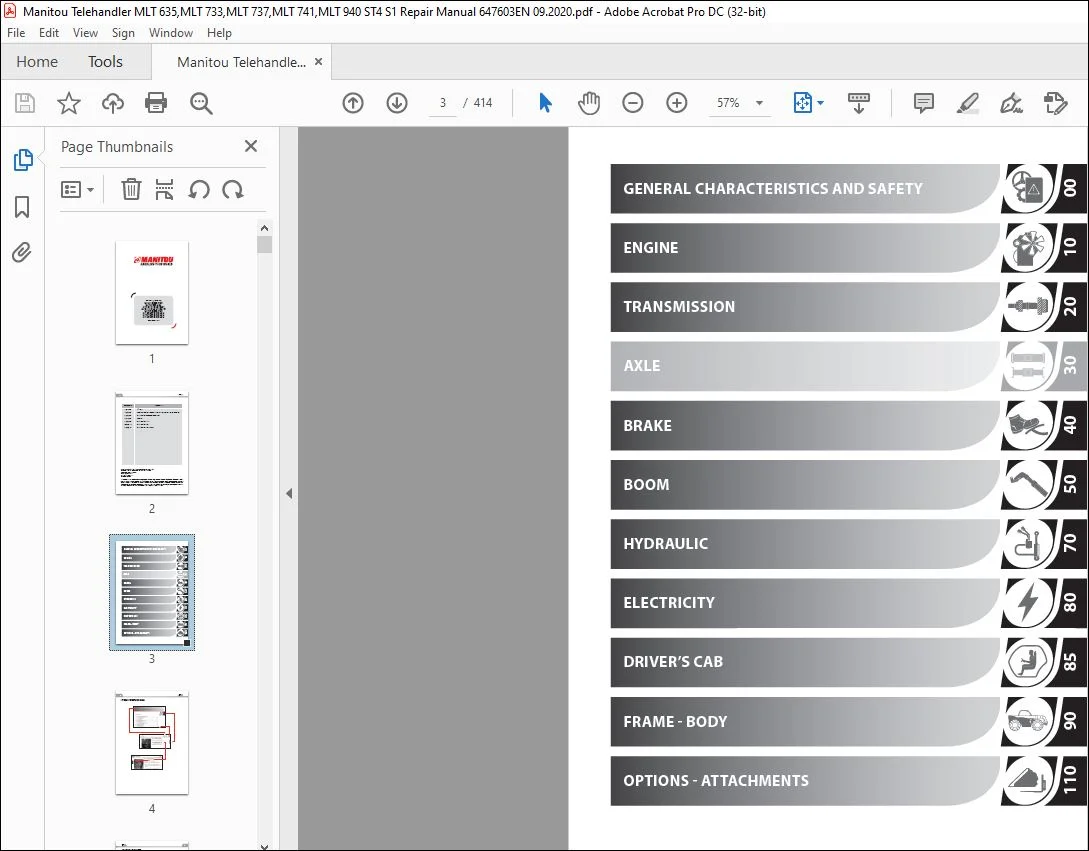
00………………………………………………………………………………………………. 9
GENERAL, CHARACTERISTICS AND SAFETY…………………………………………………………………. 10
00.1 GENERAL INSTRUCTIONS AND SAFETY NOTICE………………………………………………………. 10
00.1.1 PREAMBLE……………………………………………………………………………. 10
00.1.2 SERVICING POSITION…………………………………………………………………… 10
00.1.3 EXPLANATION OF SYMBOLS……………………………………………………………….. 11
00.1.4 SERVICING RULES……………………………………………………………………… 12
00.2 GENERAL CHARACTERISTICS AND SPECIFICATIONS…………………………………………………… 15
00.2.1 CHARACTERISTICS……………………………………………………………………… 15
00.2.2 LUBRICANTS AND FUEL………………………………………………………………….. 15
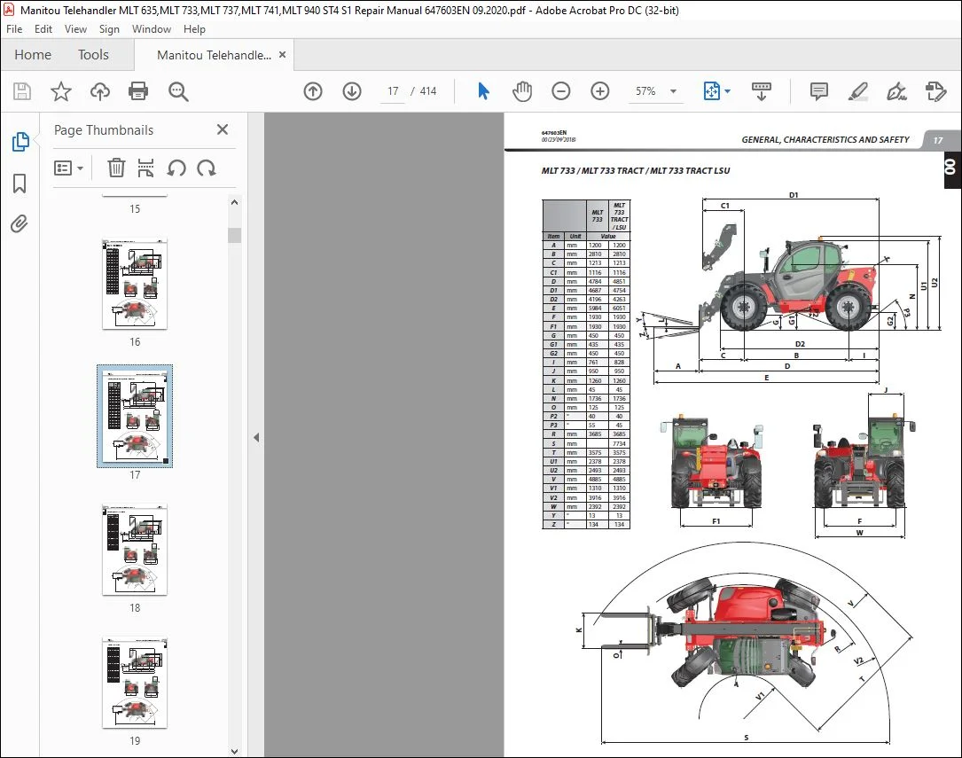
00.2.3 DIMENSIONS………………………………………………………………………….. 16
MLT 635 / MLT 737………………………………………………………………………. 16
MLT 733 / MLT 733 TRACT / MLT 733 TRACT LSU ………………………………………………. 17
MLT 635 / MLT 741 – 140 V PLUS…………………………………………………………… 18
MLT 940 – 140 V PLUS……………………………………………………………………. 19
00.3 GENERAL LOCATION………………………………………………………………………….. 20
00.3.1 NAME AND IDENTIFICATION PLATE…………………………………………………………. 20
00.4 GENERAL CONTROL AND ADJUSTMENT……………………………………………………………… 21
00.4.1 STANDARD TIGHTENING TORQUES…………………………………………………………… 21
00.4.2 METRIC – IMPERIAL UNIT CONVERSION……………………………………………………… 22
10………………………………………………………………………………………………. 23
ENGINE SPECIFICATION………………………………………………………………………………. 25
10.1 Engine characteristics and specifications……………………………………………………. 25
10.1.1 Characteristics……………………………………………………………………… 25
10.1.2 Diesel exhaust fluid (DEF)……………………………………………………………. 25
Characteristics………………………………………………………………………… 25
Levels………………………………………………………………………………… 25
Wintering……………………………………………………………………………… 25
10.1.3 Injection cycle……………………………………………………………………… 26
Effects of fuel pre-injection……………………………………………………………. 26
Effects of fuel post-injection…………………………………………………………… 26
10.1.4 Bosch CP4.1 high pressure pump………………………………………………………… 27
10.2 Engine Schematic Diagrams………………………………………………………………….. 28
10.2.1 Air intake circuit and EGR (Exhaust Gas Recirculation)…………………………………… 28
10.2.2 Lubrication circuit………………………………………………………………….. 29
10.2.3 Cooling circuit……………………………………………………………………… 30
10.2.4 Fuel circuit………………………………………………………………………… 31
10.2.5 DEF (Diesel Exhaust Fluid) circuit…………………………………………………….. 32
10.3 Engine components location…………………………………………………………………. 33
10.3.1 Engine components……………………………………………………………………. 33
10.3.2 Water and air cooling circuit…………………………………………………………. 35
10.3.3 Ventilation hydraulic circuit…………………………………………………………. 36
10.3.4 Diesel circuit………………………………………………………………………. 37
10.3.5 Fuel injection circuit……………………………………………………………….. 38
10.3.6 EGR (Exhaust Gas Recirculation) circuit………………………………………………… 39
10.3.7 DEF (Diesel Exhaust Fluid) circuit…………………………………………………….. 40
10.4 Engine controls and adjustments…………………………………………………………….. 41
10.4.1 Engine start-up authorization conditions……………………………………………….. 41
10.4.2 DEF regeneration…………………………………………………………………….. 41
10.4.3 DEF pump……………………………………………………………………………. 41
10.4.4 Engine load level……………………………………………………………………. 41
10.4.5 Ventilation regulation (MLT 733 as option)……………………………………………… 42
A – function…………………………………………………………………………… 42
B – principle of operation………………………………………………………………. 42
C – schematic diagram…………………………………………………………………… 43
D – description of hydraulic engine with control…………………………………………… 43
E – Conditions of fan adjustment components……………………………………………….. 44
10.4.6 Silent block tightening torques……………………………………………………….. 45
10.4.7 Engine tightening torques…………………………………………………………….. 45
10.4.8 Diesel fuel circuit tightening torques…………………………………………………. 46
10.4.9 Exhaust circuit tightening torques…………………………………………………….. 47
10.4.10 Cooling circuit tightening torques……………………………………………………. 49
10.4.11 Heating circuit tightening torques……………………………………………………. 50
10.5 Engine removal – refit…………………………………………………………………….. 50
10.5.1 Engine ECU removal – refit……………………………………………………………. 50
10.5.2 Air filter assembly removal…………………………………………………………… 51
10.5.3 Starter Removal……………………………………………………………………… 54
10.5.4 DOC exhaust pipe removal……………………………………………………………… 55
10.5.5 Remove the “SCR” pipe………………………………………………………………… 56
10.5.6 DEF injector removal…………………………………………………………………. 57
10.5.7 DEF tank removal…………………………………………………………………….. 58
DEF gauge removal………………………………………………………………………. 59
10.5.8 Cooler removal………………………………………………………………………. 60
Removing the upper part…………………………………………………………………. 60
Separation of cooler from engine…………………………………………………………. 62
Option 1: removal of pump and grill………………………………………………………. 65
Option 2: removal of cooler assembly……………………………………………………… 66
10.5.9 Remove the engine……………………………………………………………………. 67
Engine hose and connector removal………………………………………………………… 68
Remove the transmission universal joint (engine/angle transmission)………………………….. 70
10.5.10 ATTACHMENT BELT REMOVAL……………………………………………………………… 71
10.5.11 Engine refit……………………………………………………………………….. 72
10.5.12 Alternator removal………………………………………………………………….. 72
10.5.13 Water pump removal………………………………………………………………….. 72
10.5.14 Turbo-compressor removal. …………………………………………………………… 72
10.6 Engine troubleshooting…………………………………………………………………….. 73
10.7 Specific engine tooling……………………………………………………………………. 73
10.7.1 Special engine tooling……………………………………………………………….. 73
10.7.2 Electronic tension meter……………………………………………………………… 73
10.7.3 DEF FLUSH KIT……………………………………………………………………….. 73
20………………………………………………………………………………………………. 75
TRANSMISSION……………………………………………………………………………………… 77
20.1 Transmission schematic diagrams…………………………………………………………….. 77
20.1.1 Compact+ (C+) manual gearbox………………………………………………………….. 77
C+ DRIVE TRAIN…………………………………………………………………………. 77
C+ OPERATION OVERVIEWS………………………………………………………………….. 78
Summary table of connectors concerned by functions (C+)…………………………………….. 79
20.1.2 POWERSHIFT (PS – PG 115) gearbox………………………………………………………. 79
PS DRIVE TRAIN…………………………………………………………………………. 79
PS OPERATION OVERVIEWS………………………………………………………………….. 80
Summary table of connectors concerned by functions (PS)…………………………………….. 81
20.1.3 Hydrostatic gearbox (zf 2 HC 85)………………………………………………………. 82
DRIVE TRAIN……………………………………………………………………………. 82
OPERATION OVERVIEWS (ZF 2 hc 85)…………………………………………………………. 83
pressure connectors…………………………………………………………………….. 84
20.2 Transmission locations…………………………………………………………………….. 84
20.2.1 MECHANICAL TRANSMISSION AND GEARBOX COOLING…………………………………………….. 84
20.2.2 POWERSHIFT (PG 115) GEARBOX COMPONENTS…………………………………………………. 85
20.2.3 Hydrostatic TRANSMISSION (zf 2 HC 85)………………………………………………….. 86
20.3 Transmission controls and adjustments……………………………………………………….. 88
20.3.1 Hydrostatic auto-calibration………………………………………………………….. 88
PREPARATION……………………………………………………………………………. 88
Explanation and operation of the auto-calibration cycle…………………………………….. 88
Flow chart…………………………………………………………………………….. 88
20.3.2 Verification of machine configurations…………………………………………………. 89
20.3.3 General authorisation conditions for carriage movement…………………………………… 89
Acquisition conditions………………………………………………………………….. 89
Upkeep conditions………………………………………………………………………. 89
Loss conditions………………………………………………………………………… 89
20.3.4 Powershift – PG115 gearbox……………………………………………………………. 90
E.C.U. Transmission (X322)………………………………………………………………. 90
Automatic gear change mode………………………………………………………………. 90
Table of maximum speeds per gear…………………………………………………………. 90
SHAFT AND CLUTCH……………………………………………………………………….. 91
GEAR ASSEMBLY………………………………………………………………………….. 91
DRIVE TRAIN……………………………………………………………………………. 92
TABLE OF PRESSURES……………………………………………………………………… 93
PRESSURE TEST PORT LOCATIONS…………………………………………………………….. 94
20.3.5 Hydrostatic gearbox (zf 2 HC 85)………………………………………………………. 95
Operating mode – 2 HC 85………………………………………………………………… 96
Key for HYDROSTATIC CIRCUITS 2 HC-85……………………………………………………… 98
Diagram: Neutral……………………………………………………………………….. 99
Diagram: drive range 1…………………………………………………………………..100
Diagram: drive range 2…………………………………………………………………..101
Diagram: drive range 3…………………………………………………………………..102
20.3.6 TRANSMISSION TIGHTENING TORQUES………………………………………………………..103
MLT 635 – 737 PS………………………………………………………………………..103
MLT 733………………………………………………………………………………..104
MLT 635 – 741 – 940 V PLUS……………………………………………………………….105
20.3.7 Changing to freewheel mode (Mechanical transmission)……………………………………..105
20.3.8 Changing to freewheel mode (Hydrostatic transmission)…………………………………….105
After towing……………………………………………………………………………106
20.4 Transmission removal – refit………………………………………………………………..106
20.4.1 Powershift gearbox removal…………………………………………………………….106
PREPARATION AND SAFETY INSTRUCTIONS……………………………………………………….106
Specific tools………………………………………………………………………….106
20.4.2 Removal of the manual gearbox assembly – angle transmission……………………………….109
PREPARATION AND SAFETY INSTRUCTIONS……………………………………………………….109
Specific tools………………………………………………………………………….109
20.4.3 Remove the hydrostatic gearbox (zf 2 HC 85)……………………………………………..114
Replace the gear box…………………………………………………………………….117
20.4.4 Remove the hydrostatic pump……………………………………………………………117
Remove the hydraulic pump………………………………………………………………..117
Remove the hydrostatic pump………………………………………………………………118
20.5 Specific transmission tooling……………………………………………………………….120
20.5.1 BASIC MANOMETER BOX…………………………………………………………………..120
20.5.2 DIGITAL MANOMETER BOX…………………………………………………………………121
40……………………………………………………………………………………………….123
BRAKE…………………………………………………………………………………………….124
40.1 Brake characteristics and specifications……………………………………………………..124
40.1.1 Service brake………………………………………………………………………..124
40.1.2 Parking brake………………………………………………………………………..124
Hydrostatic transmission – cable on axle with adjustment of the sleeve………………………..124
Mechanical transmission – brake calliper at gearbox outlet…………………………………..125
40.2 Service brake schematic diagrams…………………………………………………………….125
40.3 Brake locations……………………………………………………………………………126
40.3.1 Trailer brake location………………………………………………………………..126
40.4 Brake controls and adjustment……………………………………………………………….126
40.4.1 TRAILER BRAKE VALVE TIGHTENING TORQUE…………………………………………………..126
40.4.2 Adjust brake pedal on MLT 733 105 D…………………………………………………….127
40.4.3 Adjust brake pedal on MLT 635/737 130 PS – MLT 733 105 D Tract…………………………….128
40.4.4 Adjust brake pedal on MLT 635/741/940 140 v plus…………………………………………129
40.4.5 Calibrate the inching pedal……………………………………………………………129
40.4.6 Adjusting the parking brake calliper (Mechanical transmission)…………………………….130
Adjusting the connecting rod travel……………………………………………………….130
Adjust the stop…………………………………………………………………………131
Adjust the cable tension…………………………………………………………………131
40.4.7 Adjusting the parking brake (Hydrostatic transmission)……………………………………132
40.4.8 Bleed the brakes……………………………………………………………………..133
40.4.9 Taking brake pressure on MLT 140 V PLUS…………………………………………………134
40.4.10 Towing the lift truck………………………………………………………………..134
Mechanical transmission (620.3.7 Changing to freewheel mode (Mechanical transmission), 5 105)……134
Hydrostatic transmission (620.3.8 Changing to freewheel mode (Hydrostatic transmission), 5 105)….134
40.5 Brake removal – refit………………………………………………………………………135
40.5.1 Brake master cylinder on mlt ps………………………………………………………..135
40.6 Specific brake tooling……………………………………………………………………..136
40.6.1 Hydraulic brake bleeder……………………………………………………………….136
50……………………………………………………………………………………………….137
BOOM……………………………………………………………………………………………..138
50.1 BOOM CHARACTERISTICS AND SPECIFICATIONS………………………………………………………138
50.1.1 DUPLEX BOOMS…………………………………………………………………………138
50.1.2 TRIPLEX BOOMS………………………………………………………………………..138
50.2 BOOM location……………………………………………………………………………..139
50.2.1 DUPLEX BOOM (6 and 7 m)……………………………………………………………….139
50.2.2 TRIPLEX BOOM (9 m)……………………………………………………………………140
50.3 BOOM CONTROL AND ADJUSTMENT…………………………………………………………………141
50.3.1 TELESCOPIC BOOM EXTENSION AND RETRACTION ADJUSTMENT PROCEDURE……………………………..141
TELESCOPE EXTENSION SPEED ADJUSTMENT (TRIPLEX BOOM)…………………………………………141
TELESCOPE RETRACTION SPEED ADJUSTMENT (DUPLEX AND TRIPLEX BOOM)………………………………141
INNER TELESCOPE RETRACTION DE-SYNCHRONIZATION (TRIPLEX BOOM)…………………………………141
50.3.2 RECOMMENDATION FOR FITTING SHIMS AND LUBRICATION…………………………………………142
50.3.3 Duplex TIGHTENING TORQUE AND LUBRICATION………………………………………………..143
50.3.4 Triplex TIGHTENING TORQUE AND LUBRICATION……………………………………………….144
50.4 Duplex boom removal – refit…………………………………………………………………145
50.4.1 Telescope removal…………………………………………………………………….145
50.4.2 Telescope removal…………………………………………………………………….147
Fitting of boom slide inserts…………………………………………………………….148
50.4.3 Telescopic Cylinder Removal……………………………………………………………148
Refit:…………………………………………………………………………………150
50.5 Triplex boom removal – refit………………………………………………………………..151
50.5.1 PREPARATION AND SAFETY INSTRUCTIONS…………………………………………………….151
Specific tooling:……………………………………………………………………….151
50.5.2 Telescoping circuit removal……………………………………………………………151
50.5.3 BOOM HEAD TELESCOPE T2 REMOVAL…………………………………………………………155
50.5.4 INTERMEDIATE TELESCOPE T1 REMOVAL………………………………………………………156
50.6 Special boom tools…………………………………………………………………………157
50.6.1 PIPE END PIECES………………………………………………………………………157
50.6.2 MAGNETIC LIFTER………………………………………………………………………157
70……………………………………………………………………………………………….159
HYDRAULICS………………………………………………………………………………………..161
70.1 Hydraulic characteristics and specifications………………………………………………….161
70.1.1 Dynamic steering operation…………………………………………………………….161
70.1.2 Hydraulic component sheets ……………………………………………………………163
Accumulator block……………………………………………………………………….163
OSPC 200 LS steering block……………………………………………………………….165
Pilot safety valve………………………………………………………………………167
Pilot safety valve………………………………………………………………………169
Distributor RS 14……………………………………………………………………….171
Distributor SDS 140……………………………………………………………………..177
FAN REGULATOR MOTOR (FAN DRIVE)…………………………………………………………..178
Casappa MVP 60 – 63 pump…………………………………………………………………182
Steering selector……………………………………………………………………….185
Automatic steering selector………………………………………………………………186
70.2 Hydraulic schematic diagrams………………………………………………………………..187
70.2.1 Key…………………………………………………………………………………187
70.2.2 Diagram MLT 635-737 130 PS D ST4 S1…………………………………………………….189
70.2.3 Diagram MLT 733 105 D ST4 S1…………………………………………………………..190
70.2.4 Diagram MLT 733 105 D ST4 S1 TRACT……………………………………………………..191
70.2.5 Diagram MLT 733 105 d ST4 S1 TRACT LSU………………………………………………….192
70.2.6 Diagram MLT 635 – 741 – 940 V Plus……………………………………………………..193
70.3.1 Key…………………………………………………………………………………194
70.3 Hydraulic component locations……………………………………………………………….194
70.4 Hydraulics removal – refit………………………………………………………………….195
70.4.1 Remove the hydraulic pump……………………………………………………………..195
70.4.2 Lifting cylinder removal………………………………………………………………197
70.4.3 Remove the distributor………………………………………………………………..198
70.5 Hydraulic specific tooling………………………………………………………………….201
70.5.1 Square bracket……………………………………………………………………….201
70.5.2 Distributor lifting device…………………………………………………………….201
70.5.3 DIGITAL MANOMETER BOX…………………………………………………………………202
70.5.4 BASIC MANOMETER BOX…………………………………………………………………..203
70.5.5 INFLATION KIT SET…………………………………………………………………….204
80……………………………………………………………………………………………….205
ELECTRICITY……………………………………………………………………………………….209
80.1 Electricity characteristics and specifications………………………………………………..209
80.1.1 Location of relays and fuses…………………………………………………………..209
80.1.2 Screen menus…………………………………………………………………………210
80.1.3 Electrical network architecture………………………………………………………..213
80.1.4 Electrical network architecture details…………………………………………………214
80.1.5 ECU Inputs/Outputs……………………………………………………………………215
X13/X25 – screen (A9)……………………………………………………………………215
X14 – Navigator (A4)…………………………………………………………………….216
X39-C10 – Air-conditioning ECU (A17)………………………………………………………216
X80 – Main ECU SPU 40-26 (A2) ……………………………………………………………217
X81 – Main ECU SPU 40-26 (A2) ……………………………………………………………218
X82 – Main ECU SPU 40-26 (A2) ……………………………………………………………219
X274 – Engine ECU EDC17CV52 (A19)…………………………………………………………220
X275 – Engine ECU EDC17CV52 (A19)…………………………………………………………221
X322 – Powershift gearbox ECU PG115 (A10) …………………………………………………222
X356 – Auxiliary ECU SPU 25-15 (A3) ………………………………………………………223
X357 – Auxiliary ECU SPU 25-15 (A3) ………………………………………………………224
X400 – Gearbox ECU ZF – 2HC85 _ Box CVT (A10)………………………………………………225
X401 – Gearbox ECU ZF – 2HC85 _ Box CVT (A10)………………………………………………226
80.1.6 Technical sheets for electrical components………………………………………………227
X1/X2 – starter ignition switch (A12)……………………………………………………..227
X10 – lighting commutator switch (S5)……………………………………………………..227
X11 / 12 – windscreen wiper commutator switch (S4)………………………………………….228
X34 – Outside air temperature sensor………………………………………………………228
X56 – Rotating beacon light (e15)………………………………………………………..229
X72 – Brake fluid level switch (S11)……………………………………………………..229
X74 – Accelerator potentiometer (B18)……………………………………………………..230
X75/X76 – JSM (A12)……………………………………………………………………..231
X77 – BMEP (A11)………………………………………………………………………..232
X78 – Manual accelerator…………………………………………………………………233
X79 – Stop pressure switch (B8)………………………………………………………….233
X90 to X94 – DSB (Double Switch Board) (S61 to S76)…………………………………………234
X121 – Brake pedal angular sensor (PS) (B47)……………………………………………….235
X225 – DEF tank gauge (B53)………………………………………………………………236
X245 – Supercharged air cooler temperature sensor…………………………………………..237
X246 – Transmission oil cooler temperature sensor…………………………………………..237
X247 – Hydraulic fluid cooler temperature sensor……………………………………………238
X252 – VENTILATION CONTROL ELECTROVALVE……………………………………………………238
X253 – VENTILATION inversion ELECTROVALVE………………………………………………….239
X265 – Fuel level sensor (R2)…………………………………………………………….239
X300 – Angle boom potentiometer (B23)……………………………………………………..240
X334 – Telescope retracted position sensor (S34)……………………………………………241
X382 – Brake circuit pressure switch (B30)…………………………………………………241
80.2 Wiring diagrams……………………………………………………………………………242
80.2.1 Examples of coding on the wiring diagrams ………………………………………………242
80.2.2 Cable marking on an electrical wiring harness……………………………………………243
80.2.3 MLT 635/737 130 PS D ST4 S1……………………………………………………………244
Positions of connectors by diagram………………………………………………………..244
Diagram 1 – Starting…………………………………………………………………….246
Diagram 2 – Networks (CAN & lin)………………………………………………………….248
Diagram 3 – Transmission…………………………………………………………………250
Diagram 4 – Hydraulics…………………………………………………………………..252
Diagram 5 – Sensor………………………………………………………………………254
Diagram 6 – Ventilation, wipers and air-conditioning………………………………………..256
Diagram 7 – Options……………………………………………………………………..258
Diagram 8 – Signalling and lighting……………………………………………………….260
80.2.4 MLT 733 105 D ST4 S1 + TRACT + LSU……………………………………………………..262
Positions of connectors by diagram………………………………………………………..262
Diagram 1 – Starting…………………………………………………………………….264
Diagram 2 – Networks (CAN & lin)………………………………………………………….266
Diagram 3 – Transmission…………………………………………………………………268
Diagram 4 – Hydraulics…………………………………………………………………..270
Diagram 5 – Sensor………………………………………………………………………272
Diagram 6 – Ventilation, wipers and air-conditioning………………………………………..274
Diagram 7 – Options……………………………………………………………………..276
Diagram 8 – Signalling and lighting……………………………………………………….278
80.2.5 MLT 635/741/940 140 V plus d ST4 S1……………………………………………………280
Positions of connectors by diagram………………………………………………………..280
Diagram 1 – Starting…………………………………………………………………….282
Diagram 2 – CAN & lin networks……………………………………………………………284
Diagram 3 – Transmission…………………………………………………………………286
Diagram 4 – Hydraulics…………………………………………………………………..288
Diagram 5 – Sensor………………………………………………………………………290
Diagram 6 – Ventilation, wipers and air-conditioning………………………………………..292
Diagram 7 – Options……………………………………………………………………..294
Diagram 8 – Signalling and lighting……………………………………………………….296
80.3 Electricity locations………………………………………………………………………298
80.3.1 MLT mechanical transmission……………………………………………………………298
Key……………………………………………………………………………………298
Frame 3D PS Harness……………………………………………………………………..301
Frame 3D Mechanical Harness ……………………………………………………………..302
Cab 3D mechanical & PS harness……………………………………………………………303
Engine 3D MLT mechanical & PS harness……………………………………………………..304
Deutz engine 3D harness………………………………………………………………….305
Frame 2D PS Harness……………………………………………………………………..306
Frame 2D Mechanical Harness………………………………………………………………307
Cab 2D PS harness……………………………………………………………………….308
Cab 2D mechanical harness………………………………………………………………..309
Engine 2D harness……………………………………………………………………….310
Distributor 2D harness…………………………………………………………………..311
80.3.2 MLT V plus…………………………………………………………………………..312
Key……………………………………………………………………………………312
Frame 3D V plus MLT 6 & 7 harness…………………………………………………………315
Frame 3D V plus MLT 9 harness…………………………………………………………….316
Cab 3D v plus harness …………………………………………………………………..317
Engine 3D MLT V plus harness……………………………………………………………..318
Deutz engine 3D harness………………………………………………………………….319
Frame 2D V plus harness………………………………………………………………….320
Distributor 2D harness…………………………………………………………………..321
80.4 Electrical removal – refit………………………………………………………………….322
80.4.1 Remove the battery……………………………………………………………………322
80.4.2 Remove the engine ECU…………………………………………………………………323
Refit………………………………………………………………………………….323
80.4.3 Remove the main ECU “SPU 40-26”………………………………………………………..324
80.4.4 Remove the transmission ECU……………………………………………………………324
Powershift “pg115”………………………………………………………………………324
Hydrostatic “ZF EC2 B”…………………………………………………………………..324
80.4.5 Remove the auxiliary ECU “SPU 25-15”……………………………………………………324
80.4.6 Remove the dashboard screen……………………………………………………………325
80.4.7 Remove – Replace JSM on BMEP…………………………………………………………..326
80.4.8 Replace the strain gauge………………………………………………………………327
Location……………………………………………………………………………….327
Axle preparation………………………………………………………………………..328
Characteristics of products used………………………………………………………….328
Characteristics of the fixing screws………………………………………………………329
Assembly precautions and tightening torque…………………………………………………329
80.5 Electrical troubleshooting………………………………………………………………….332
80.5.1 Error codes (DTC)…………………………………………………………………….332
Air-conditioning ECU DTC (X39-C10)………………………………………………………..332
Main SPU ECU DTC 40-26 (X80 – X81 – X82) …………………………………………..333
Engine ECU DTC EDC17CV52 (X274 – X275)…………………………………………………….337
Transmission ECU DTC PS+ PowershifT PG115 (X322)……………………………………………354
Auxiliary ECU DTC SPU 25-15 (X356 – X357)………………………………………………….355
Transmission ECU DTC CVT (X400 – X401 – 2HC85)……………………………………………..358
80.6 Specific electric tooling…………………………………………………………………..360
80.6.1 Spark gap boxes………………………………………………………………………360
80.6.2 Electrovalve adapter………………………………………………………………….360
80.6.3 Diagnostic tools……………………………………………………………………..361
DIAGNOSTICS CASE………………………………………………………………………..361
CONNECTIONS TO THE LIFT TRUCK…………………………………………………………….362
ENGINE ADAPTATION KIT……………………………………………………………………362
85……………………………………………………………………………………………….363
DRIVER’S CAB………………………………………………………………………………………364
85.1 Driver’s cab control and adjustment………………………………………………………….364
85.1.1 Tightening torques……………………………………………………………………364
Cab silent block………………………………………………………………………..364
Air-conditioning………………………………………………………………………..364
85.2 Removal – refitting driver’s cab…………………………………………………………….365
85.2.1 Cab removal………………………………………………………………………….365
85.2.2 Windscreen removal……………………………………………………………………368
Procedure for opening the protective grille………………………………………………..368
85.2.3 Door winder removal…………………………………………………………………..370
Door trim panel removal………………………………………………………………….370
Removal of door interior…………………………………………………………………371
Refit………………………………………………………………………………….373
85.2.4 Cab door removal……………………………………………………………………..376
85.2.5 Windscreen wiper motor removal…………………………………………………………377
85.2.6 Cab lower trim removal………………………………………………………………..379
85.2.7 Upper dashboard removal……………………………………………………………….380
85.2.8 Heating block removal…………………………………………………………………382
85.2.9 Driver’s seat removal…………………………………………………………………385
85.2.10 Armrest removal……………………………………………………………………..386
85.2.11 Dashboard switch removal……………………………………………………………..387
85.3 Specific cab tooling……………………………………………………………………….388
85.3.1 Cab grille hinge kit………………………………………………………………….388
90……………………………………………………………………………………………….389
FRAME – BODYWORK…………………………………………………………………………………..390
90.1 Removal – refitting frame – bodywork…………………………………………………………390
90.1.1 Removing the engine cover……………………………………………………………..390
110……………………………………………………………………………………………… 0
110 AIR-CONDITIONING OPTION…………………………………………………………………………393
110.1 Air conditioning characteristics and specifications…………………………………………..393
110.1.1 Description of operation……………………………………………………………..393
110.1.2 Operating principle………………………………………………………………….394
110.1.3 Air-conditioning ECU Inputs/Outputs……………………………………………………396
110.1.4 Evaporator temperature probe characteristics……………………………………………397
110.2 Schematic diagram of automatic air-conditioning………………………………………………398
110.2.1 Schematic diagram …………………………………………………………………..398
110.3 Air-conditioning locations…………………………………………………………………399
110.3.1 Location and tightening torques……………………………………………………….399
110.3.2 HVAC interior components……………………………………………………………..400
110.3.3 HVAC exterior components……………………………………………………………..400
110.3.4 Automatic air-conditioning locations…………………………………………………..401
Key to locations of automatic air-conditioning……………………………………………..402
110.3.5 Condenser components…………………………………………………………………402
110.4 Air conditioning controls and adjustments……………………………………………………403
110.4.1 General check points…………………………………………………………………403
110.4.2 ASSEMBLY INSTRUCTIONS FOR AIR-CONDITIONING CIRCUIT………………………………………403
110.4.3 Safety measures for handling r134a…………………………………………………….404
110.4.4 Refrigerant fluid load for the air conditioning circuit………………………………….404
110.4.5 Check the evaporator temperature sensor………………………………………………..405
110.5 Air conditioning removal – refit……………………………………………………………407
110.5.1 Air-conditioning belt removal…………………………………………………………407
110.5.2 Air conditioning belt refit…………………………………………………………..408
110.6 Air conditioning troubleshooting……………………………………………………………409
110.6.1 Temperature TROUBLESHOOTING…………………………………………………………..409
110.6.2 ABNORMAL NOISE ON A/C SYSTEM………………………………………………………….409
110.6.3 UNPLEASANT SMELL…………………………………………………………………….409
110.6.4 X39 (C10) – Automatic air-conditioning error codes (DTC)…………………………………410
110.7 Specific air conditioning tooling…………………………………………………………..410
110.7.1 Fitting wedge for elastic drive belt…………………………………………………..410
110 Intelligent hydraulics OPTION……………………………………………………………………411
110.1 Intelligent hydraulics characteristics and specifications……………………………………..411
110.2 Location of components…………………………………………………………………….412
110.2.1 Assembly on 6 or 7 metre boom…………………………………………………………412
110.2.2 Assembly on 9 metre boom……………………………………………………………..413
PLEASE NOTE:
- This is the SAME exact manual used by your dealers to fix your vehicle.
- The same can be yours in the next 2-3 mins as you will be directed to the download page immediately after paying for the manual.
- Any queries / doubts regarding your purchase, please feel free to contact [email protected]
S.V