Manitou Telehandler MLT635, MLT733, MLT737, MLT741, MLT940 PLUS ST5 S1 Repair Manual 647867EN – PDF DOWNLOAD
Original price was: $77.95.$31.95Current price is: $31.95.
Manitou Telehandler MLT635, MLT733, MLT737, MLT741, MLT940 PLUS ST5 S1 Repair Manual 647867EN – PDF DOWNLOAD
MLT 635 130 PS D ST5 S1
MLT 635 140 V PLUS D ST5 S1
MLT 733 115 D ST5 S1
MLT 733 115 D ST5 S1 TRACT LSU
MLT 737 130 PS D ST5 S1
MLT 741 140 V PLUS D ST5 S1
MLT 940 140 V PLUS D ST5 S1
Description
Manitou Telehandler MLT635, MLT733, MLT737, MLT741, MLT940 PLUS ST5 S1 Repair Manual 647867EN – PDF DOWNLOAD
FILE DETAILS:
Manitou Telehandler MLT635, MLT733, MLT737, MLT741, MLT940 PLUS ST5 S1 Repair Manual 647867EN – PDF DOWNLOAD
Language : English
Pages : 690
Downloadable : Yes
File Type : PDF
Size: 78.4 MB
IMAGES PREVIEW OF THE MANUAL:
Contact us: [email protected]
https://vimeo.com/777551446
DESCRIPTION:
Manitou Telehandler MLT635, MLT733, MLT737, MLT741, MLT940 PLUS ST5 S1 Repair Manual 647867EN – PDF DOWNLOAD
MLT 635 130 PS D ST5 S1
MLT 635 140 V PLUS D ST5 S1
MLT 733 115 D ST5 S1
MLT 733 115 D ST5 S1 TRACT LSU
MLT 737 130 PS D ST5 S1
MLT 741 140 V PLUS D ST5 S1
MLT 940 140 V PLUS D ST5 S1
This brochure is provided for information only. Any reproduction, copy, representation, recording, transfer,
distribution, etc., in whole or in part, in any format whatsoever, is prohibited. The diagrams, drawings, images,
comments and indications found in this documentation, and the organization of the document itself, are intellectual
property of MANITOU BF. Any violation of the above is subject to civil and criminal penalties. The logos and visual
identity of the company are property of MANITOU BF and may not be used without express formal authorization. All
rights reserved.
Any reproduction, source code access, decompilation, modification, copy (other than backup copies), correction of
errors, transmission or distribution of any software built into Manitou machines is strictly prohibited.
In the event that the measures above nevertheless prove essential to enable use of the software, in accordance
with its destination, or to obtain the information required for interoperability with other software created
independently, the user should contact Manitou in advance and may, at its sole discretion, take the necessary
measures or give access to only the information strictly necessary for interoperability.
Any breach of these requirements is likely to constitute a counterfeiting offense subject to legal action by Manitou.
Connected Manitou machines are equipped with boxes that collect technical data on the machines (such as geotracking
data or data on component operation). This data, which is organized, processed and enhanced by
algorithms and expertise proprietary to Manitou, constitutes a protected database under Article L.341-1 of the
Intellectual Property Code.
TABLE OF CONTENTS:
Manitou Telehandler MLT635, MLT733, MLT737, MLT741, MLT940 PLUS ST5 S1 Repair Manual 647867EN – PDF DOWNLOAD
00. GENERAL AND SAFETY CHARACTERISTICS 14
00.1. FOREWORD…………………………………………………………………………………………………………………. 14
00.2. LIST OF ABBREVIATIONS…………………………………………………………………………………………… 14
00.3. WORK DURING THE WARRANTY PERIOD ……………………………………………………………….. 16
00.4. MAINTENANCE POSITION………………………………………………………………………………………….. 16
00.5. EXPLANATION OF SYMBOLS…………………………………………………………………………………….. 16
00.6. MAINTENANCE RULES ………………………………………………………………………………………………. 17
00.7. LIST OF SUPPLIER DOCUMENTATION ……………………………………………………………………… 20
00.8. CHARACTERISTICS AND SPECIFICATIONS …………………………………………………………….. 20
00.8.1 Weights and forces …………………………………………………………………………………………………………….20
00.8.2 Lubricants and fuels ……………………………………………………………………………………………………………21
00.8.3 Dimensions – MLT 635 130 PS D ST5 S1 ………………………………………………………………………………..22
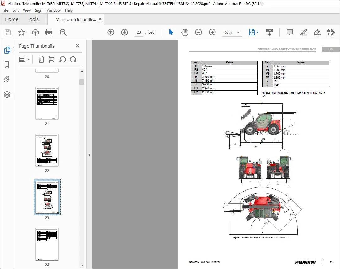
00.8.4 Dimensions – MLT 635 140 V PLUS D ST5 S1………………………………………………………………………….23
00.8.5 Dimensions – MLT 733 115 D ST5 S1, MLT 733 115 D ST5 S1 TRACT LSU…………………………………….25
00.8.6 Dimensions – MLT 737 130 PS D ST5 S1 ………………………………………………………………………………..27
00.8.7 Dimensions – MLT 741 140 V PLUS D ST5 S1 ………………………………………………………………………….28
00.8.8 Dimensions – MLT 940 140 V PLUS D ST5 S1………………………………………………………………………….30
00.9. LOCATION……………………………………………………………………………………………………………………. 31
00.9.1 Name and identification plates ………………………………………………………………………………………………31
00.10. CONTROL AND ADJUSTMENT ………………………………………………………………………………… 32
00.10.1 Standard tightening torques ………………………………………………………………………………………………..32
00.10.2 Metric – imperial unit conversion …………………………………………………………………………………………..34
10. ENGINE 35
10.1. CHARACTERISTICS AND SPECIFICATIONS …………………………………………………………….. 35
10.1.1 Engine characteristics 115 hp ……………………………………………………………………………………………….35
10.1.2 Engine characteristics 130 hp ……………………………………………………………………………………………….35
10.1.3 Engine characteristics 140 hp ……………………………………………………………………………………………….35
10.1.4 Diesel exhaust fluid (DEF) ……………………………………………………………………………………………………36
10.1.5 Fan control ……………………………………………………………………………………………………………………….36
10.1.6 Conditions of fan control components ……………………………………………………………………………………..37
10.2. FLOW DIAGRAMS AND SCHEMATIC DIAGRAMS…………………………………………………….. 39
10.2.1 Ventilation principle diagram …………………………………………………………………………………………………39
10.2.2 Intake system and EGR……………………………………………………………………………………………………….39
10.2.3 Lubrication system ……………………………………………………………………………………………………………..40
4 647867EN-USM134(A-12/2020)
TABLE OF CONTENTS
10.2.4 Cooling system ………………………………………………………………………………………………………………….41
10.2.5 Fuel system………………………………………………………………………………………………………………………41
10.2.6 DEF circuit ……………………………………………………………………………………………………………………….42
10.3. LOCATION……………………………………………………………………………………………………………………. 44
10.3.1 Engine location ………………………………………………………………………………………………………………….44
10.3.2 Water cooling system ………………………………………………………………………………………………………….46
10.3.3 Air intake circuit …………………………………………………………………………………………………………………46
10.3.4 Diesel fuel circuit………………………………………………………………………………………………………………..46
10.3.5 Fuel injection circuit…………………………………………………………………………………………………………….47
10.3.6 Exhaust system …………………………………………………………………………………………………………………48
10.4. CONTROL AND ADJUSTMENT…………………………………………………………………………………… 48
10.4.1 Engine start-up authorization conditions ………………………………………………………………………………….48
10.4.2 Stationary regeneration authorization conditions ……………………………………………………………………….48
10.4.3 DEF pump cleaning preparation …………………………………………………………………………………………….49
10.4.4 DEF pump cleaning procedure………………………………………………………………………………………………49
10.4.5 Engine load level ……………………………………………………………………………………………………………….51
10.4.6 Fan check points………………………………………………………………………………………………………………51
10.4.7 Engine suspension tightening torques …………………………………………………………………………………….52
10.4.8 V plus coupling tightening torques ………………………………………………………………………………………….52
10.4.9 Gearbox coupling torques…………………………………………………………………………………………………….52
10.5. REMOVAL…………………………………………………………………………………………………………………….. 53
10.5.1 Remove the engine hood……………………………………………………………………………………………………..53
10.5.2 Remove the upper rear casing ………………………………………………………………………………………………53
10.5.3 Remove the lower rear casing……………………………………………………………………………………………….53
10.5.4 Disconnect the battery…………………………………………………………………………………………………………53
10.5.5 Removing the belt casing……………………………………………………………………………………………………..54
10.5.6 Removing the expansion tank ……………………………………………………………………………………………….54
10.5.7 Removing the DEF injector …………………………………………………………………………………………………..55
10.5.8 Remove the DOC-DPF pot …………………………………………………………………………………………………..55
10.5.9 Remove the thermal engine (hydrostatic machine) …………………………………………………………………….55
10.5.10 Remove the intermediate exhaust pipe ………………………………………………………………………………….60
10.5.11 Remove the SCR pot…………………………………………………………………………………………………………60
10.5.12 Remove the starter……………………………………………………………………………………………………………61
10.5.13 Remove the alternator ……………………………………………………………………………………………………….62
10.5.14 Remove the air filter ………………………………………………………………………………………………………….62
10.5.15 Removing the turbo …………………………………………………………………………………………………………..62
10.5.16 Removing the engine ECU………………………………………………………………………………………………….63
10.5.17 Removing the air conditioning compressor belt………………………………………………………………………..63
TABLE OF CONTENTS
647867EN-USM134(A-12/2020) 5
10.6. REFIT……………………………………………………………………………………………………………………………. 64
10.6.1 Removing the air conditioning compressor belt………………………………………………………………………….64
10.7. TROUBLESHOOTING………………………………………………………………………………………………….. 64
10.7.1 Fault table ………………………………………………………………………………………………………………………..64
10.8. SPECIFIC TOOLING…………………………………………………………………………………………………….. 67
10.8.1 DEF flush kit ……………………………………………………………………………………………………………………..67
10.8.2 Electronic belt tensiometer……………………………………………………………………………………………………67
10.8.3 Fitting wedge for elastic drive belt…………………………………………………………………………………………..67
20. TRANSMISSION 68
20.1. CHARACTERISTICS AND SPECIFICATIONS …………………………………………………………….. 68
20.1.1 Gearbox PG115 (PS+) ………………………………………………………………………………………………………..68
20.2. FLOW DIAGRAMS AND SCHEMATIC DIAGRAMS…………………………………………………….. 71
20.2.1 Gearbox Compaq+ (C+) ………………………………………………………………………………………………………71
20.2.2 Gearbox PG115 (PS+) ………………………………………………………………………………………………………..74
20.2.3 Gearbox DANA CVT 318 (V+)……………………………………………………………………………………………….79
20.3. LOCATION……………………………………………………………………………………………………………………. 83
20.3.1 Mechanical transmission Compaq+ (C+)………………………………………………………………………………….83
20.3.2 Mechanical transmission PG115 (PS+)……………………………………………………………………………………84
20.3.3 Hydrostatic transmission Dana CVT 318 (V+)……………………………………………………………………………88
20.4. CONTROL AND ADJUSTMENT…………………………………………………………………………………… 90
20.4.1 Check the machine configurations………………………………………………………………………………………….90
20.4.2 General authorization conditions for carriage movement ……………………………………………………………..91
20.4.3 Free the wheels by removing the universal joints ……………………………………………………………………….91
20.4.4 Transmission PG115 (PS+)…………………………………………………………………………………………………..92
20.4.5 Transmission Compaq+ (C+) ………………………………………………………………………………………………..93
20.4.6 Transmission Dana CVT 318 (V+) ………………………………………………………………………………………….93
20.5. REMOVAL…………………………………………………………………………………………………………………….. 99
20.5.1 Preparation and safety instructions…………………………………………………………………………………………99
20.5.2 Remove the boom shaft casing …………………………………………………………………………………………… 100
20.5.3 Transmission MLT 733 (C+) ……………………………………………………………………………………………….. 100
20.5.4 Transmission MLT PS+ …………………………………………………………………………………………………….. 105
20.5.5 Transmission Dana CVT 318 (V+) ……………………………………………………………………………………….. 107
6 647867EN-USM134(A-12/2020)
TABLE OF CONTENTS
20.6. SPECIFIC TOOLING…………………………………………………………………………………………………… 117
20.6.1 Basic manometer box……………………………………………………………………………………………………….. 117
20.6.2 Digital manometer box………………………………………………………………………………………………………. 117
30. AXLE 118
30.1. CHARACTERISTICS AND SPECIFICATIONS …………………………………………………………… 118
30.1.1 Characteristics of axle 212 with negative brake ………………………………………………………………………. 118
30.1.2 Characteristics of axle 212…………………………………………………………………………………………………. 119
30.2. LOCATION…………………………………………………………………………………………………………………..120
30.2.1 Location of axles……………………………………………………………………………………………………………… 120
30.3. CONTROL AND ADJUSTMENT………………………………………………………………………………….120
30.3.1 Rear axle pin adjustment clearance……………………………………………………………………………………… 120
30.3.2 Transmission tightening torques………………………………………………………………………………………….. 120
40. BRAKE 122
40.1. CHARACTERISTICS AND SPECIFICATIONS ……………………………………………………………122
40.1.1 Service brake – Specifications of oil bath disc brakes ……………………………………………………………….. 122
40.1.2 Functional principle of the accumulator load valve (VACA) ………………………………………………………… 122
40.2. LOCATION…………………………………………………………………………………………………………………..123
40.2.1 Location of brake circuit MLT 733 ………………………………………………………………………………………… 123
40.2.2 Location of brake circuit MLT PS+ ……………………………………………………………………………………….. 124
40.2.3 Location of brake circuit MLT V+………………………………………………………………………………………….. 124
40.2.4 Location of trailer hydraulic brake MLT V+……………………………………………………………………………… 125
40.2.5 Location of pressure connectors for brake circuits …………………………………………………………………… 126
40.2.6 Location of the trailer pneumatic brake …………………………………………………………………………………. 127
40.3. CONTROL AND ADJUSTMENT………………………………………………………………………………….129
40.3.1 Pressure connector tightening torque — rear axle …………………………………………………………………… 129
40.3.2 Pressure connector tightening torque — front axle…………………………………………………………………… 129
40.3.3 Adjusting the service brake pedal MLT 733 ……………………………………………………………………………. 129
40.3.4 Adjusting the service brake pedal MLT PS+ & MLT V+ ……………………………………………………………… 130
40.3.5 Adjusting the inching potentiometer on the brake pedal…………………………………………………………….. 130
40.3.6 Calibrating the inching function …………………………………………………………………………………………… 131
40.3.7 Calibrating the inching point……………………………………………………………………………………………….. 131
40.3.8 Towing the machine …………………………………………………………………………………………………………. 131
TABLE OF CONTENTS
647867EN-USM134(A-12/2020) 7
40.3.9 Bleeding the service brakes ……………………………………………………………………………………………….. 131
40.3.10 Bleeding the parking brakes……………………………………………………………………………………………… 132
40.3.11 Bleed the trailer brake circuit (CL) ………………………………………………………………………………………. 132
40.3.12 Purging the trailer brake circuit valve ………………………………………………………………………………….. 132
40.3.13 Freewheel the axle with the negative brake ………………………………………………………………………….. 133
40.4. SPECIFIC TOOLING……………………………………………………………………………………………………134
40.4.1 Basic manometer box……………………………………………………………………………………………………….. 134
40.4.2 Digital manometer box………………………………………………………………………………………………………. 134
50. LIFTING STRUCTURE 135
50.1. CHARACTERISTICS AND SPECIFICATIONS ……………………………………………………………135
50.1.1 Duplex Boom………………………………………………………………………………………………………………….. 135
50.1.2 Triplex boom…………………………………………………………………………………………………………………… 136
50.2. FLOW DIAGRAMS AND SCHEMATIC DIAGRAMS……………………………………………………136
50.2.1 Duplex Boom………………………………………………………………………………………………………………….. 136
50.2.2 Triplex boom…………………………………………………………………………………………………………………… 139
50.3. LOCATION…………………………………………………………………………………………………………………..143
50.3.1 Duplex Boom………………………………………………………………………………………………………………….. 143
50.3.2 Triplex boom…………………………………………………………………………………………………………………… 144
50.4. CONTROL AND ADJUSTMENT………………………………………………………………………………….146
50.4.1 Chock the boom hinges …………………………………………………………………………………………………….. 146
50.4.2 Duplex Boom………………………………………………………………………………………………………………….. 146
50.4.3 Triplex boom…………………………………………………………………………………………………………………… 153
50.5. REMOVAL……………………………………………………………………………………………………………………161
50.5.1 Duplex Boom………………………………………………………………………………………………………………….. 161
50.5.2 Triplex boom…………………………………………………………………………………………………………………… 168
50.6. REFIT…………………………………………………………………………………………………………………………..177
50.6.1 Duplex Boom………………………………………………………………………………………………………………….. 177
50.7. SPECIFIC TOOLING……………………………………………………………………………………………………179
50.7.1 Pipe end pieces ………………………………………………………………………………………………………………. 179
50.7.2 Magnetic lifter …………………………………………………………………………………………………………………. 179
8 647867EN-USM134(A-12/2020)
TABLE OF CONTENTS
70. HYDRAULICS 180
70.1. CHARACTERISTICS AND SPECIFICATIONS ……………………………………………………………180
70.1.1 Steering pump & steering unit OSPR LS ……………………………………………………………………………….. 180
70.2. FLOW DIAGRAMS AND SCHEMATIC DIAGRAMS……………………………………………………182
70.2.1 Hydraulic schematic diagram — MLT 635/737 130 PS D ST5 S1 ………………………………………………… 183
70.2.2 Hydraulic schematic diagram – MLT 635/741/940 140 v plus D ST5 S1…………………………………………. 187
70.2.3 Hydraulic schematic diagram — MLT 733 115 D ST5 S1 …………………………………………………………… 191
70.2.4 Hydraulic schematic diagram — MLT 733 115 D ST5 S1 TRACT LSU………………………………………….. 195
70.3. LOCATION…………………………………………………………………………………………………………………..199
70.3.1 Location of hydraulic components – MLT 635 130 PS D ST5 S1 ………………………………………………….. 199
70.3.2 Location of hydraulic components – MLT 635 140 V PLUS D ST5 S1……………………………………………. 201
70.3.3 Location of hydraulic components – MLT 733 115 D ST5 S1 ………………………………………………………. 203
70.3.4 Location of hydraulic components – MLT 733 115 D ST5 S1 TRACT LSU ……………………………………… 204
70.3.5 Location of hydraulic components – MLT 737 130 PS D ST5 S1 ………………………………………………….. 205
70.3.6 Location of hydraulic components – MLT 741 140 V PLUS D ST5 S1……………………………………………. 207
70.3.7 Location of hydraulic components – MLT 940 140 V PLUS D ST5 S1……………………………………………. 208
70.4. CONTROL AND ADJUSTMENT………………………………………………………………………………….209
70.4.1 Purge the air in the distributor SDS140 (MLT 733 115 D ST5 S1) ………………………………………………… 209
70.4.2 Tightening torques for hydraulic system fasteners …………………………………………………………………… 210
70.4.3 Tightening torques for the hydraulic pump tank suction hose clamps……………………………………………. 211
70.4.4 Tightening torques for the double pump 44.2/22.9 cm³ ……………………………………………………………… 212
70.4.5 Tightening torques for the double pump 63/22.46 cm³ ………………………………………………………………. 213
70.4.6 Tightening torques for counterbalance valve flap (triplex intermediate boom cylinder) ……………………… 213
70.4.7 Tightening torques for counterbalance valve flap (boom lifting cylinder)………………………………………… 214
70.4.8 Tightening torques for counterbalance valve flap (boom lifting cylinder and duplex telescopic boom
cylinder)…………………………………………………………………………………………………………………. 214
70.4.9 Tightening torques for counterbalance valve flap (duplex boom tilting cylinder) ………………………………. 214
70.5. REMOVAL……………………………………………………………………………………………………………………214
70.5.1 Preparation and safety instructions………………………………………………………………………………………. 214
70.5.2 Drain the hydraulic tank …………………………………………………………………………………………………….. 215
70.5.3 Remove the auxiliary hydraulic pump …………………………………………………………………………………… 215
70.5.4 Remove the main hydraulic pump ……………………………………………………………………………………….. 215
70.5.5 Remove the distributor ……………………………………………………………………………………………………… 216
70.5.6 Remove the lifting cylinder…………………………………………………………………………………………………. 217
TABLE OF CONTENTS
647867EN-USM134(A-12/2020) 9
70.6. REFIT…………………………………………………………………………………………………………………………..220
70.6.1 Install the tilting cylinder hoses……………………………………………………………………………………………. 220
70.7. SPECIFIC TOOLING……………………………………………………………………………………………………220
70.7.1 Square bracket ……………………………………………………………………………………………………………….. 220
70.7.2 Valve bank lifting device ……………………………………………………………………………………………………. 221
70.7.3 Basic manometer box……………………………………………………………………………………………………….. 221
70.7.4 Digital manometer box………………………………………………………………………………………………………. 221
70.7.5 Inflation kit……………………………………………………………………………………………………………………… 222
80. ELECTRICITY 223
80.1. CHARACTERISTICS AND SPECIFICATIONS ……………………………………………………………223
80.1.1 Electrical component sheets ………………………………………………………………………………………………. 223
80.1.2 ECU Inputs / Outputs ……………………………………………………………………………………………………….. 233
80.2. FLOW DIAGRAMS AND SCHEMATIC DIAGRAMS……………………………………………………241
80.2.1 Electrical diagrams – MLT 733 …………………………………………………………………………………………….. 243
80.2.2 Electrical diagrams – MLT PS ……………………………………………………………………………………………… 267
80.2.3 Electrical diagrams – MLT V+ ……………………………………………………………………………………………… 289
80.3. LOCATION………………………………………………………………………………………………………………….. 311
80.3.1 Location of relays and fuses……………………………………………………………………………………………….. 311
80.3.2 Electrical locations MLT 635 130 PS D ST5……………………………………………………………………………. 313
80.3.3 Electrical locations MLT 737 130 PS D ST5……………………………………………………………………………. 339
80.3.4 Electrical locations MLT 635 140 V PLUS D ST5 …………………………………………………………………….. 365
80.3.5 Electrical locations MLT 741 140 V PLUS D ST5……………………………………………………………………… 391
80.3.6 Electrical locations MLT 940 140 V PLUS D ST5 …………………………………………………………………….. 417
80.3.7 Locations of electrical MLT 733 115 D ST5…………………………………………………………………………….. 445
80.3.8 Electrical locations MLT 733 115 D Trac LSU ST5 …………………………………………………………………… 467
80.3.9 Automatic air conditioning location ………………………………………………………………………………………. 489
80.4. CONTROL AND ADJUSTMENT………………………………………………………………………………….490
80.4.1 Tightening torques of the engine wiring harness components – MLT 635/737 130 PS………………………. 490
80.4.2 Tightening torques of the engine wiring harness components – MLT 635/741/940 140 V PLUS………….. 491
80.4.3 Tightening torques of the engine wiring harness components – MLT 733 115 (& TRACT LSU) …………… 492
80.4.4 Tightening torques of the chassis wiring harness components – MLT 635/737 130 PS and MLT 733
115 (+ TRACT LSU)………………………………………………………………………………………………….. 493
80.4.5 Tightening torques of the chassis wiring harness components – MLT 635/741/940 140 V PLUS…………. 493
80.4.6 JSM tightening torques……………………………………………………………………………………………………… 494
80.4.7 Harmony display tightening torques……………………………………………………………………………………… 494
10 647867EN-USM134(A-12/2020)
TABLE OF CONTENTS
80.5. REMOVAL……………………………………………………………………………………………………………………494
80.5.1 Removing the battery ……………………………………………………………………………………………………….. 494
80.5.2 Removing the engine ECU…………………………………………………………………………………………………. 495
80.5.3 Removing the main ECU …………………………………………………………………………………………………… 496
80.5.4 Remove the PowerShift transmission ECU (MLT 635/737 130 PS) ……………………………………………… 496
80.5.5 Remove the hydrostatic transmission ECU (MLT 635/741/940 140 V PLUS)………………………………….. 497
80.5.6 Removing the auxiliary ECU (option) ……………………………………………………………………………………. 497
80.5.7 Remove the dashboard screen …………………………………………………………………………………………… 498
80.5.8 Removing/Refitting the JSM……………………………………………………………………………………………….. 498
80.5.9 Removing the strain gage ………………………………………………………………………………………………….. 499
80.6. REFIT…………………………………………………………………………………………………………………………..500
80.6.1 Refitting the strain gage…………………………………………………………………………………………………….. 500
80.6.2 Refitting the engine ECU …………………………………………………………………………………………………… 503
80.7. TROUBLESHOOTING…………………………………………………………………………………………………504
80.7.1 DTC ECU Harmony screen………………………………………………………………………………………………… 504
80.7.2 DTC Main ECU (SPU 40-26)………………………………………………………………………………………………. 505
80.7.3 DTC auxiliary ECU (SPU 25-15-STD2) or (SPU 40-26 PWM) …………………………………………………….. 513
80.7.4 Error code transmission RC 12–10–30 …………………………………………………………………………………. 519
80.7.5 Correspondence of injector fault codes …………………………………………………………………………………. 597
80.7.6 Engine error code ……………………………………………………………………………………………………………. 597
80.7.7 Automatic air conditioning error codes ………………………………………………………………………………….. 618
80.7.8 Error codes table …………………………………………………………………………………………………………….. 619
80.8. SPECIFIC TOOLING……………………………………………………………………………………………………620
80.8.1 Breakout boxes……………………………………………………………………………………………………………….. 620
80.8.2 Electrovalve adapter ………………………………………………………………………………………………………… 621
85. OPERATOR STATION 622
85.1. CHARACTERISTICS AND SPECIFICATIONS ……………………………………………………………622
85.1.1 Description of air conditioning operation………………………………………………………………………………… 622
85.2. FLOW DIAGRAMS AND SCHEMATIC DIAGRAMS……………………………………………………623
85.2.1 Schematic diagrams…………………………………………………………………………………………………………. 623
85.3. LOCATION…………………………………………………………………………………………………………………..625
85.3.1 Operator station general locations ……………………………………………………………………………………….. 625
85.3.2 Specific air conditioning locations………………………………………………………………………………………… 628
TABLE OF CONTENTS
647867EN-USM134(A-12/2020) 11
85.4. CONTROL AND ADJUSTMENT………………………………………………………………………………….632
85.4.1 General controls and adjustments ……………………………………………………………………………………….. 632
85.4.2 Air conditioning controls and adjustments ……………………………………………………………………………… 637
85.5. REMOVAL……………………………………………………………………………………………………………………642
85.5.1 Removing the cab ……………………………………………………………………………………………………………. 642
85.5.2 Removing the windshield with standard grille …………………………………………………………………………. 645
85.5.3 Removing the door window winder ………………………………………………………………………………………. 647
85.5.4 Remove the cab door ……………………………………………………………………………………………………….. 650
85.5.5 Removing the windshield wiper motor…………………………………………………………………………………… 651
85.5.6 Removing the cab lower trim………………………………………………………………………………………………. 653
85.5.7 Removing the upper dashboard ………………………………………………………………………………………….. 654
85.5.8 Removing the armrest block ………………………………………………………………………………………………. 656
85.5.9 Removing the driver’s seat…………………………………………………………………………………………………. 656
85.5.10 Removing the heating unit ……………………………………………………………………………………………….. 657
85.5.11 Removing the dashboard switches …………………………………………………………………………………….. 660
85.6. REFIT…………………………………………………………………………………………………………………………..660
85.6.1 Removing the door window winder ………………………………………………………………………………………. 660
85.6.2 Air conditioning assembly instructions ………………………………………………………………………………….. 663
85.7. TROUBLESHOOTING…………………………………………………………………………………………………664
85.7.1 Troubleshooting on the air conditioning system ………………………………………………………………………. 664
85.8. SPECIFIC TOOLING……………………………………………………………………………………………………665
85.8.1 Cab grille hinge kit……………………………………………………………………………………………………………. 665
90. CHASSIS 666
110. ADDITIONAL EQUIPMENT 667
110.1. MANUAL CENTRAL GREASING………………………………………………………………………………667
110.1.1 Manual central greasing system tightening torques ………………………………………………………………… 667
110.2. AUTOMATIC CENTRAL GREASING ………………………………………………………………………..668
110.2.1 Automatic greasing characteristics and specifications …………………………………………………………….. 668
110.2.2 Schematic diagram of the distributors …………………………………………………………………………………. 672
110.2.3 Location of automatic central greasing components – MLT 635…………………………………………………. 675
110.2.4 Location of automatic central greasing components – MLT 733/737/741……………………………………… 677
110.2.5 Location of automatic central greasing components – MLT 940…………………………………………………. 679
12 647867EN-USM134(A-12/2020)
TABLE OF CONTENTS
110.2.6 Automatic central greasing controls and adjustments ……………………………………………………………… 681
110.2.7 Tightening torques of automatic central greasing connections…………………………………………………… 682
110.2.8 Troubleshooting …………………………………………………………………………………………………………….. 682
110.3. SEMI-AUTOMATIC WHEEL ALIGNMENT ………………………………………………………………..685
110.3.1 Location of semi-auto wheel realignment……………………………………………………………………………… 685
120. DIAGNOSTIC TOOLS AND SOFTWARE 686
120.1. DIAGNOSTICS CASE ……………………………………………………………………………………………….686
120.2. COMPONENT DIAGNOSTICS BOX………………………………………………………………………….687
120.3. CABLE PLUG OBD – PLUG DEUTZ………………………………………………………………………….687
120.4. DIAGNOSTIC TOOL FOR THE HYDROSTATIC TRANSMISSION …………………………..687
120.5. CABLE NETWORK M12/RJ45 ………………………………………………………………………………….688
PLEASE NOTE:
- This is the same manual used by the dealers to diagnose and troubleshoot your vehicle
- You will be directed to the download page as soon as the purchase is completed. The whole payment and downloading process will take anywhere between 2-5 minutes
- Need any other service / repair / parts manual, please feel free to contact [email protected] . We still have 50,000 manuals unlisted
S.V