Manitou Telehandler MT1135,MT1335 100D ST5 S1 Repair Manual 647802EN-USM134 – PDF DOWNLOAD
Original price was: $78.00.$28.95Current price is: $28.95.
Manitou Telehandler MT1135,MT1335 100D ST5 S1 Repair Manual 647802EN-USM134 – PDF DOWNLOAD
Description
Manitou Telehandler MT1135 MT1335 100D ST5 S1 Repair Manual 647802EN-USM134 – PDF DOWNLOAD
IMAGES PREVIEW OF THE MANUAL:
DESCRIPTION:
Manitou Telehandler MT1135 MT1335 100D ST5 S1 Repair Manual 647802EN-USM134 – PDF DOWNLOAD
00.1. FOREWORD
This chapter deals with the general instructions and safety notice during servicing checks and work. The other instructions and warning texts are indicated in the chapters concerned
In order to reduce the risk of accidents, please:
• Follow the instructions in the operator’s manual and
the truck servicing instructions.
• > This manual should be found in all trucks.
• Please follow the safety instructions.
• Use the appropriate tools for all work to be carried
out.
• Use original Manitou spare parts.
If these instructions are not followed there is a risk of accidents occurring, the severity of which could go as far as causing death. A person who follows the safety instructions and a wellserviced machine make a safe, effective and profitable combination
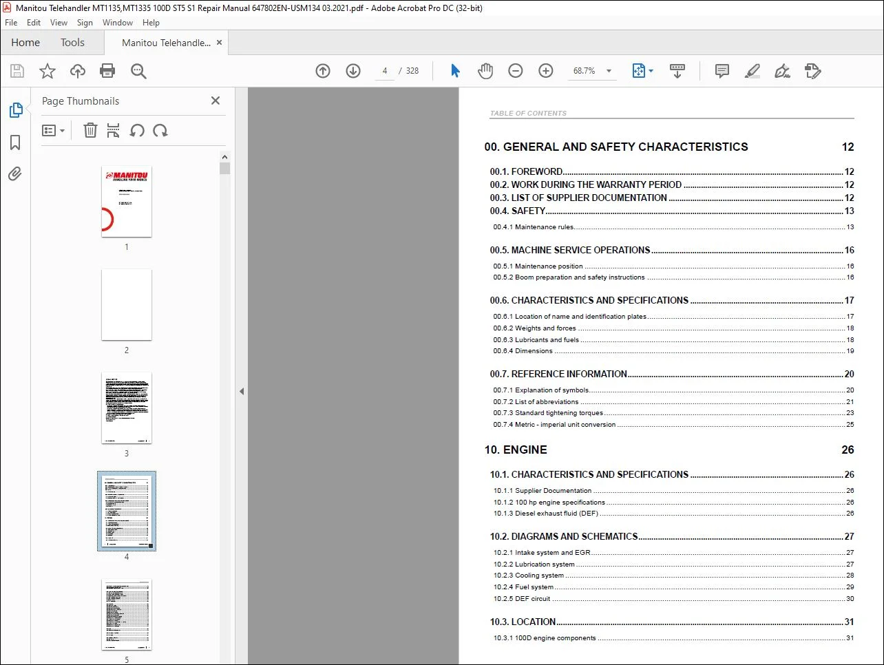
TABLE OF CONTENTS:
Manitou Telehandler MT1135 MT1335 100D ST5 S1 Repair Manual 647802EN-USM134 – PDF DOWNLOAD
Legal disclaimer 3
Foreword 12
Intervention during the warranty period 12
Supplier Documentation List 12
Safety 13
Servicing Rules 13
Machine Service Operations 16
Servicing position 16
Preparation and safety instructions for the boom 16
Characteristics and specifications 17
Location of name & identification plates 17
Location of name and identification plates 17
Mass & stress 18
Lubricants & fuel 18
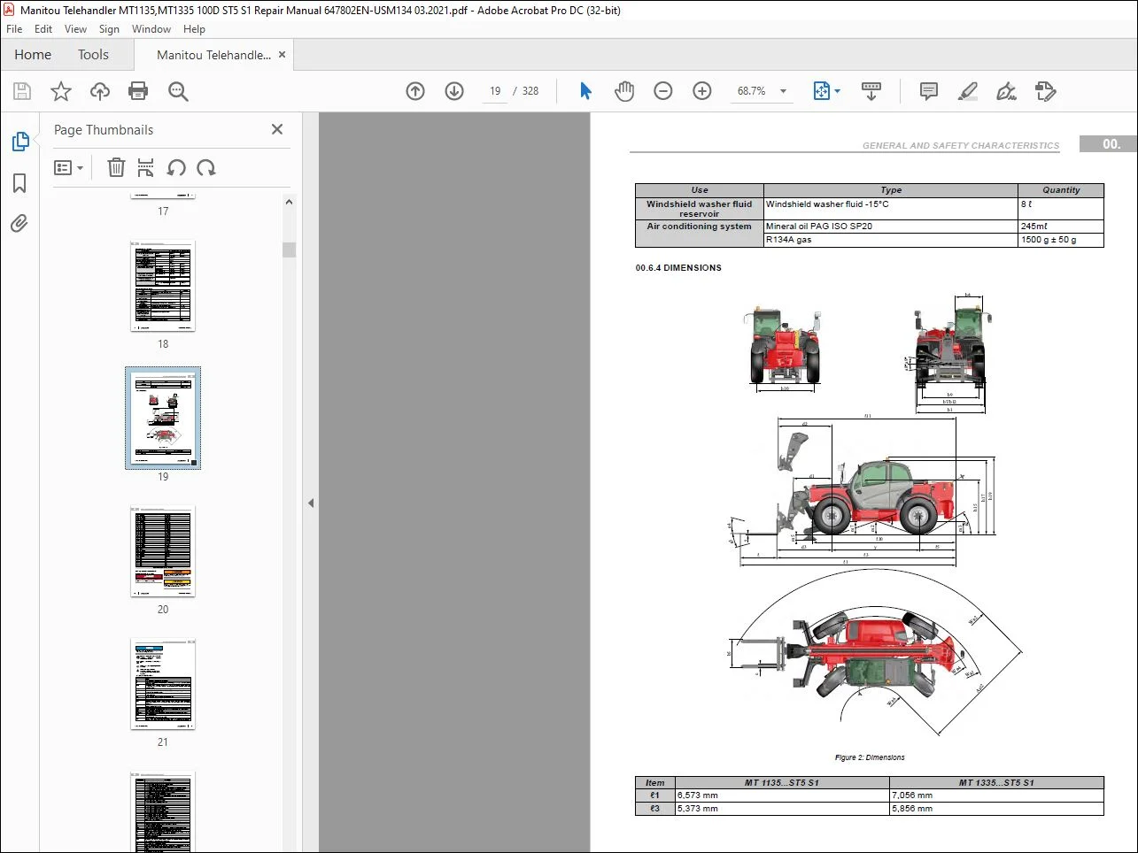
Dimensions 19
Dimensions 19
Reference information 20
Explanation of symbols 20
List of Abbreviations 21
Standard tightening torques 23
Metric – imperial unit conversion 25
Characteristics and specifications 26
Supplier documentation 26
Engine Specifications (3 6L 100 hp) 26
Diesel exhaust fluid (DEF) 26
Diagrams and schematics 27
Intake and EGR circuit 27
Intake system and EGR 27
Key 27
Lubrication circuit 27
Lubrication system 28
Key 28
Cooling system 28
Cooling system 29
Key 29
Fuel circuit 29
Fuel system 30
Key 30
DEF circuit 30
Location 31
Location of engine components Deutz 3 6L 100D ST5 31
100D engine components 31
Key 31
3D Location of cooling circuit components 100D 32
Location of cooling system components MT 100D) 32
3D Diesel fuel circuit MT 100D 32
3D Diesel fuel system MT 100D 33
3D Diesel fuel system MT 100D 33
3D Diesel Exhaust Fluid line MT 100D 34
3D Diesel Exhaust Fluid line MT 100D 34
3D Diesel Exhaust Fluid line MT 100D 34
Control and adjustment 35
Tightening torques for exhaust 100D 35
Exhaust assembly tightening torques 35
Permission condition for engine start 35
Regeneration conditions and constraints 35
Prepare DEF pump cleaning 36
Removing the rear cab casing 36
Disconnecting the hoses connected to the DEF pump 36
DEF pump cleaning procedure 36
Hoses connected between the pump and the tank 37
Hoses connected between the pump and the tank 37
Hoses connected between the pump and the tank 37
Hoses connected between the pump and the tank 37
Circuit priming 37
Inducement levels 37
Fan drive Check point 38
Removal 38
Remove the starter 75/100D 38
Removing the diesel filter and disconnecting the connector 39
Disconnecting the battery + 39
Removing the starter 39
Remove the belt guard 75/100D 39
Removing the belt casing 39
Remove the accessory belt 75/100D 39
Removing the attachment belt 40
Remove the air conditioning belt 75/100D 40
Removing the air conditioning belt 40
Remove the alternator 75/100D 40
Remove the alternator 40
Remove the diesel filter 75/100D 40
Removing the fuel filter 41
Remove air conditioning compressor 75/100D 41
Remove the 2 access panels 41
Remove exhaust pipe 100D 42
Removing the cover from the engine housing 42
Disconnecting the SCR connectors 42
Removing the angle piece 43
Remove the muffler 43
Remove DOC-DPF assembly 100D 43
Removing the insulation 43
Removing the angle piece 43
Disconnecting the DEF 44
Unscrewing the DOC-DPF bracket 44
Removing the DOC-DPF assembly 44
Remove the exhaust line 100D 44
Disconnecting the DEF 44
Disconnecting the SCR connectors 44
Unscrewing the exhaust mount pad 44
Undoing the DOC-DPF clamp 45
Undoing the 6 screws from the exhaust line bracket 45
Removing the coolant tank 45
Slinging from the exhaust line bracket rings 45
Removing the exhaust line bracket assembly 45
Remove the expansion tank 75/100D 45
Undoing the tank support screws 46
Removing the hoses 46
Remove the radiator 100D 46
Removing the radiator hoses 46
Disconnecting the supercharged air cooling hoses 46
Removing the radiator support bracket fasteners 47
Undoing the lower radiator tie rod 47
Sling the radiator 47
Remove the hydraulic engine-fan assembly 100D 47
Disconnecting the supercharged air cooling hose 47
Remove fuel tank 48
Draining the fuel tank 48
Battery cover removal 48
Removing the battery and the step 48
Unscrewing the front cab casing 49
Disconnecting the windshield washer hose 49
Removing casing under fuel and oil tanks 49
Disconnecting the fuel hoses and pipes 49
Removing the two fuel tank retaining screws on the chassis 49
Removing the fuel tank screws on the hydraulic tank 49
Removing the fuel tank support screw from the front of the chassis 50
Remove the engine housing 50
Removing the engine housing rear access panel and supports 50
Removing the engine housing front access panel and supports 50
Unscrewing the lower radiator tie rod 50
Remove the engine 100D MECH 51
Disconnecting the engine connectors 51
Unclipping the wiring harness 51
Disconnecting the engine ground X122 51
Removing the glow plug power supply X257 52
Disconnecting the alternator X179 and the ground 52
Disconnecting the 2 heating hoses 52
Disconnecting the cooler hoses 52
Removing the 13 gearbox exterior fastening screws 52
Removing the 4 screws from the converter 53
Sling the engine 53
Removing the 3 exhaust side support screws 53
Removing the 3 radiator side support screws 53
Refit 53
Refit the exhaust line 100D 53
Refitting the exhaust line 54
Troubleshooting 54
Engine troubleshooting procedure 54
Specific tooling 57
Cleaning DEF kit 57
DEF flush kit 57
Electronic belt tensiometer 57
Electronic belt tensiometer 57
Characteristics and specifications 58
Supplier documentation 58
Diagrams and schematics 58
Mechanical transmission 58
Transmission drive chain MECH 58
Kinematic chain of transmission assembly (100 hp) 58
Key 58
Gearbox 58
Front and rear axles 59
35 km/h option front and rear axles 59
Transmission operation schematic MECH 59
Neutral schematic diagram 59
Forward gear schematic diagram 60
Reverse gear schematic diagram 60
Transmission synoptic MECH 61
Operation overview – mechanical transmission 61
Location 62
Mechanical transmission 62
Location of ports on PSR09 gearbox 62
Location of gearbox ports 62
Control and adjustment 62
Mechanical transmission 62
Tightening torques for transmission 100D/100P 62
Tightening torques for transmission assembly – 100 hp (with tilt) 62
Tightening torques for gearbox coupling MECH 63
Gearbox/engine coupling tightening torques 63
Adjustment values for pressure ports MECH 63
Location of pressure connectors – mechanical transmission 63
Locking the 4th gear PSR09 gearbox 64
Gearbox plug 64
Gearbox screw 64
Removal 64
Mechanical transmission 64
Removing the gearbox ST5 non-HA 64
Cover plate 65
Draining the gearbox 65
Gearbox universal joint 65
Hose support 65
Gearbox coupling cover 66
Alternator casing 66
Engine/gearbox coupling 66
Hose support 66
Hose support 67
Hose support 67
Connectors on gearbox 67
Gearbox control lever 67
Gearbox outlet hose 68
Parking brake hose 68
Gearbox inlet hose 68
Pallet truck under the engine-gearbox assembly 68
Gearbox mounting 69
Gearbox attachment bolts 69
Gearbox fastening screws 69
Gearbox fastening screws 69
Mount and gearbox fastening screws 70
Gearbox fastening screws 70
Pallet truck under the engine-gearbox assembly 70
Engine/gearbox assembly 70
Gearbox fastening screws 71
Gearbox fastening screws 71
Gearbox only 71
Troubleshooting 71
DTC for transmission 71
Specific tooling 71
Digital manometer kit 71
Digital manometer box 71
Basic manometer kit 72
Basic manometer box — overview 72
Machined socket (50 mm diameter) 72
Machined 50 mm socket 72
Characteristics and specifications 73
Supplier documentation 73
Control and adjustment 73
Tightening torques of the tilt correction plate 73
Frame leveling plate tightening torques 73
Bleeding the axle blocking cylinder 73
Characteristics and specifications 75
Master Cylinder specifications 75
Service brake specifications 75
Parking brake specifications 75
Diagrams and schematics 77
Mechanical transmission 77
Service brake diagram 77
Service brake schematic diagram 77
Parking brake diagram 78
Parking brake schematic diagram 78
Location 79
Location of service brake components 79
Location of service brake components 79
Control and adjustment 80
Mechanical transmission 80
Tightening torques for brake circuit ST5 80
Braking circuit tightening torques 80
Adjusting the service brake ST5 80
Adjustment of the service brake pedal stop 80
Bleeding the service brake circuit ST5 81
Adjusting the parking brake 82
Bleeding the parking brake circuit 82
Freewheeling MECH 83
Removal 84
General safety measures before brake removal operations 84
Removing the parking brake 84
Removing the master cylinder 85
Specific tooling 87
Hydraulic brake bleed kit 554019 87
Hydraulic brake bleed kit 87
Parking brake bleeding harness 265865 87
Parking brake bleeder harness 87
Characteristics and specifications 88
Boom description 11/13 m 88
Triplex boom slinging point 88
Location 89
Location of components for boom 89
Location of 11 m and 13 m boom components 89
Control and adjustment 89
Adjusting telescope extension/retraction time on triplex boo 89
Outer telescoping valve 90
Inner telescoping valve 90
Pads and greasing areas 90
Triplex boom pads and lubrication zones 91
Boom pads with straight edges 92
Boom pads with beveled edges 92
Tightening torques and greasing areas 93
Boom tightening torque 93
Removal 95
Removing the complete boom 95
Compensating cylinder pin 95
Lifting cylinder pin 95
Rear casing 95
Clamps 95
Boom position sensor attachment 96
Connectors X134 and X262 96
Hoses to be removed 96
Clamp 96
Boom head cylinder supply hose 97
Boom pin 97
Boom slinging rings 97
Removing the boom circuit 98
Boom 98
Rear casing 98
Clamps 98
Connectors X100 and X134 99
Boom retraction sensor switch attachment 99
Boom angle sensor attachment 99
Boom head supply hoses 99
Internal cylinder telescoping supply hoses 100
Boom head access panel 100
Tilting and attachment supply hoses 100
Tilting cylinder upper pin 100
Telescopic boom cylinder retaining nut 101
Fixing screw 101
Strap around the telescopic boom cylinder foot 101
Hydraulic assembly extended 101
Removing the telescope T1 and T2 101
Pad cover plates and cages 102
Strap on telescope T2 102
Telescope T2 stand and strap 102
Telescope T1 cylinder attachment 102
Refit 103
Installing the complete boom 103
Installing the telescope T1 103
Lower pads 103
Telescope T1 in the boom foot 103
Cages and lower pads 104
Retraction of telescope T1 into the boom foot 104
T1 front upper pads 104
RH side pads 104
Pad cover plates 105
Telescope T1 cylinder sliding surfaces and washer 105
Rear upper pads, right rear side pads and crowbar 105
Left side pads and upper cover plates 105
Installing the telescope T2 106
Lower pads 106
Cages and lower pads 106
RH side pads 106
Pad cover plates 107
Magnet, pad cover plate and hose guide 107
Rear upper pads and left side pads 107
Upper pad cover plate 107
Magnet, pad cover plate and hose guide 108
Washer and nut 108
Installing the boom circuit 108
Flat of the cylinder rod vertical 108
Hoses in the upper channels 109
Attaching the flange 109
Screws (4), screws (5) and washers (6) 109
Cylinder head fastener 109
Tilting cylinder axle 110
Hoses on attachment circuit pipes 110
Tilting cylinder hoses 110
Telescope head closing panel 110
Pipes, screws and washers 111
Boom foot hoses 111
Attaching the potentiometer 111
Boom retracted switch attachment 111
Rear-view mirror and rear casing 112
Specific tooling 112
Pipe end pieces 112
Pipe end piece 112
Magnetic lifter 112
Magnetic lifter 113
Characteristics and specifications 114
List of hydraulic components MT1135/1335 100D ST5 114
FP HP hydraulic supply unit 52624601 114
3D representation of the FP HP feed block with remote accumulator 115
3D representation of the FP HP feed block with connected accumulator 115
Location of FP HP feed block components 116
Hydraulic diagram of FP HP feed block 116
AVBSOSE33CCAP-FC2-5,4 single safety valve 52523724 118
3D representation 118
Cross-sectional view of single safety valve 119
Hydraulic diagram 119
AVBSOSE-33 single safety valve 303310 119
3D representation of the CSP 119
Sectional representation of the CSP 119
Hydraulic diagram of the CSP 119
VBSODE-42 dual safety valve 311172 120
3D representation of the CSPD 120
Sectional representation of the CSPD 120
Hydraulic diagram of the CSPD 120
VBSODENN-38 dual safety valve 285635 120
3D representation of the CSPD 120
Hydraulic diagram of the CSPD 120
AVBSODE-30 dual safety valve 52525895 120
3D representation of the CSPD 121
Hydraulic diagram of the CSPD 121
SD 8/7 control valve 52607672 121
3D representation of the valve bank SD 8/7 121
Hydraulic diagram of valve bank SD 8/7 122
Main diagram of the inlet element (EE) 122
Schematic diagram of the tilting element (EI) 123
Schematic diagram of the lifting element (EL) 124
Main diagram of the left stabilizer element (ESG) 124
Main diagram of the slope corrector component (ECD) 125
Main diagram of the attachment element (EA) 126
Boosted master cylinder 52627389 126
3D representation of power-assisted brake master cylinder 126
Location of assisted braking master cylinder components 126
Hydraulic diagram of the power-assisted brake master cylinder 127
LAGU 250/125 140B direction pump 311437 128
3D representation of the steering pump and connector correspondence 128
Hydraulic diagram of the steering pump 129
Location of internal steering pump elements 130
3-Position steering selector 131
3D view of 3-position steering selector 131
Hydraulic diagram of the 3-position steering selector 131
Discharge valve 103007MAN02 (276214) 131
3D representation of the discharge valve 132
Exploded view of the discharge valve 132
Hydraulic diagram of the discharge valve 132
Flow regulation valve 288003 132
3D representation of the flow rate control valve 132
Hydraulic diagram of the flow rate control valve 132
Hydraulic diagram (max flow rate) 133
Hydraulic diagram (flow rate X%) 133
Diagrams and schematics 133
Hydraulic schematic – MT 100D 135
Key to diagram abbreviations 135
Key to items 136
Key to values 137
Hydraulic diagram 1 139
Hydraulic diagram 2 140
Hydraulic diagram 3 141
Location 143
Location of hydraulic components – MT 11/13 100D ST5 143
Location of hydraulic components – MT 11/13 100D ST5 143
Control and adjustment 144
Checking service brake hydraulic circuit FP HP supply unit 144
Check the service brake circuit 144
Service brake circuit pressure fault 144
Operation of the isolation valve (VIC) 144
Pressure ports on hydraulic circuit MT 11/13 100D ST5 145
Pressure connections of the hydraulic assembly 145
Tightening torques for main distributor (except for A) 146
Main distributor tightening torques 146
Tightening torques for accumulator block (except for A) 146
Tightening torques of the braking/steering hydraulic block (100D) 146
Removal 147
Securing the machine before hydraulic removal operations 147
Remove the main distributor 147
Removing the flap support cover 147
Remove the boom shaft access panel 147
Removing the JSM case 148
Disconnecting the distributor_1 148
Disconnecting the distributor hoses 148
Disconnect connectors X71, X72, X75, X77, X78 and X81 to X86 148
Removing the 3 distributor fastening bolts 149
Remove the hydraulic pump 149
Removing the seat assembly and its support bracket 149
Disconnecting the 2 hoses at the rear of the pump 149
Disconnect the hoses 149
Remove the accumulator block 150
Removing the boom shaft casing 150
Disconnecting the hoses, coupling and connectors 150
Removing the accumulator block 150
Remove the axle lock cylinder 150
Remove a stabilizer cylinder 150
Removing the stabilizer electrovalve cover 151
Disconnect the stabilizer electrovalve 151
Removing the stabilizer pins 151
Removing the stabilizer 151
Remove the tilt correction cylinder 151
Lower the stabilizers and place a container under the leveling cylinder 152
Disconnect the two leveling cylinder hoses 152
Remove the mountings and the cylinder pin 152
Specific tooling 153
Basic manometer kit 153
Basic manometer box — overview 153
Digital manometer kit 153
Digital manometer box 153
Characteristics and specifications 154
Fuses and Relays 154
Fuses and relays in the cab 154
List of fuses in the cab 154
List of relays in the cab 155
Motor fuses and relays 100D 155
List of fuses under the engine hood 155
List of relays under the engine hood 155
ECU Inputs/Outputs 156
Input/Output Harmony ECU 156
Harmony screen 156
Connector X13 156
Connector X14 156
Input/Output SPU 40-26 ECU Mech 157
Key 157
Connector X112 157
Key 158
Connector X113 158
Key 159
Connector X114 160
Input/Output ECM engine control unit 100 D 161
Connector X174 161
Connector X175 162
Input/Output SPU 40-26 ECU PWM 164
Key 164
Connector X148 165
Key 165
Connector X149 166
Key 166
Connector X150 167
Input/Output SPU 25-15 Std2 168
Key 168
Connector X148 168
Key 168
Connector X149 169
Air conditioning auto ECU IN/OUT 169
Connector C10 169
Technical sheets for electrical components 170
Table of Electricals Technicals DataSheets 170
Ignition switch 172
Rotating beacon light-554935 172
Wiper combination switch 173
air filter clogging indicator 174
Lighting combination switch 174
Reverse warning 175
Front horn 175
DSB 176
switch_746448 177
12V socket 177
Electrovalve transmission 178
transmission pressure switch 178
transmission temperature sensor 179
fuel water sensor 179
transmission speed sensor 180
Fuel gage 315265-320410 180
JSM 181
12-pin connector 181
2-pin connector 182
4-pin connector 182
Pressure switch 52502269 182
Spool position sensor 183
Safety electrovalve 184
Angle sensor_288253 184
Angle of potentiometer (1) depending on voltage (2) 185
Centering of the adjustment range 185
contact position 186
emergency stop 186
BMEP 187
Diagram 187
Electrovalve PVEH 188
Electrovalve PVEA 188
Throttle pedal angle sensor (52500209) 189
release valve 189
water level sensor 190
Strain gage 52506420 190
Flow regulation valve 288003 191
Diagrams and schematics 192
CAN synoptic MECH 192
CAN and LIN operating diagram 192
Electrical Diagram Codification 193
Example of an electrical diagram 193
Electrical marking of cables 194
Cable marking on an electrical wiring harness 194
Position by Schematic – MT…100D 194
Electrical Schematics – MT…100D 209
Diag 1: Start-up electrical diagram – MT 100D 209
Diag 1: Start-up electrical diagram – MT 100D 211
Diag 2: Electrical diagram, Networks (CAN / ECU ) – MT 100D 212
Diag 2: Electrical diagram, Networks (CAN / ECU ) – MT 100D 214
Diag 3: Electrical diagram Transmission – ML 100D 215
Diag 3: Electrical diagram Transmission – ML 100D 217
Diag 4: Electrical diagram, Hydraulic Movements – MT 100D 218
Diag 4: Electrical diagram, Hydraulic Movements – MT 100D 220
Diag 5: Electrical diagram, Sensors – MT 100D 221
Diag 5: Electrical diagram, Sensors – MT 100D 223
Diag 6: Electrical diagram, Ventilation, Wipers and Air-conditioning – MT 100D 224
Diag 6: Electrical diagram, Ventilation, Wipers and Air-conditioning – MT 100D 226
Diag 7: Electrical diagram options – MT 100D 227
Diag 7: Electrical diagram options – MT 100D 228
Diag 8: Electrical diagram, Lights and Signals – MT 100D 229
Diag 8: Electrical diagram, Lights and Signals – MT 100D 231
Location 233
Electrical locations MT 100D 235
3D location of electrical components – MT 100D 235
3D location of electrical components – MT 100D 236
2D location of engine electrical components – MT 100D 237
2D location of engine electrical components – MT 100D 239
3D location of chassis electrical components – MT 100D 240
3D location of chassis electrical components – MT 100D 242
2D location of chassis electrical components – MT 100D 243
2D location of chassis electrical components – MT 100D 246
3D location of cabin electrical components – MT 100D 247
3D location of cabin electrical components – MT 100D 249
2D location of cabin electrical components – MT 100D 250
2D location of cabin electrical components – MT 100D 252
Control and adjustment 253
Adjusting the boom sensor 253
Work zone 253
Adjusting the longitudinal stability warning and limiting 253
Checking the cut-off of aggravating hydraulic movements 254
Calibrate the angle sensor boom 254
Lifting the boom 254
Adjustment values to be obtained 254
Boom lowering 254
Removal 254
Remove the fuses and relays cab cover 254
Access panel 255
Remove the fuses and relays engine cover 100 D 255
Engine fuse and relay box cover 255
Remove the engine control unit 75/100D 255
Disconnect the ECU connectors 255
Remove the fastening screws 256
Remove the cab control unit 256
Rear housing 256
Connectors X112, X113 and X114 256
Remove combined instrument panel 256
Fastening screws and connectors 256
Remove the strain gage localization 256
Location of the strain gage 257
Removing the JSM from the BMEP 257
Refit 257
Install the strain gage localization 257
Contact surface cleaning 258
Contact zone sanding 258
Result of sanding 258
Jack under the rear axle 258
Stands under rear axle 259
Stands positioned under the rear axle 259
Gage identification 259
Glue on the gage 259
Tightening the screws 260
Knocking the screws 260
Marking the screws 260
Installing the protective cover 260
Verification of marks 260
Install JSM on the BMEP 260
Tightening the locknut 261
Example 1 261
Example 2 261
Troubleshooting 261
DTC Motor Deutz ST5 261
DTC Main ECU (SPU 40-26-PWM) P350-New Ag) 282
DTC Auxiliary calculator (SPU 25-15 STD2) 291
Air conditioning error codes (DTC) 297
Specific tooling 298
Solenoid valve adapter 298
Electrovalve adapter 298
Breakout boxes 298
Breakout boxes 298
Characteristics and specifications 299
Safety measures for handling the R134a 299
Air conditioning description of operation 299
Diagrams and schematics 300
Air conditioning operating principle 300
Air conditioning schematic diagram 300
Location 302
Location air conditioning 302
HVAC interior components 302
Key to interior components 302
HVAC exterior components 303
Key to HVAC exterior components 303
Location automatic air conditioning 304
Automatic air conditioning unit 304
Key to automatic air conditioning unit 304
Location condenser components 305
Condenser 305
Control and adjustment 305
Safety measures for handling the R134a 305
Air conditioning check the evap temp sensor 306
Automatic air conditioning connector 306
Manual air conditioning connector 306
Evaporator temperature measurement 306
Sensor position on the evaporator 306
Tester on automatic air conditioning unit temperature sensor 307
Tester on manual air conditioning unit temperature sensor 307
Air conditioning control 307
Air conditioning assembly instructions 307
Tightening torque old cab 308
Air conditioning components tightening torques on cab 308
Tightening torques for the cabin shocks mounts 309
Cab suspension silent block tightening torques 309
General check point air conditioning 309
Removal 310
Remove the condenser 310
Remove the cab lower trim 310
Lower dashboard trim panel 310
Remove the front cab cover 310
Front cab casing 310
Remove the electric windows system Cab 310
Motor and door window assembly 310
Door trim panel removal 311
Window up support fastener 311
Window up motor connector 311
Window up motor removal 311
Remove the rear cab cover 311
Rear cab casing 312
Remove the cab 312
Side flap 312
Condenser casing 312
Air conditioning hose casing 312
Condenser unit 313
Cab and ECU connectors 313
Rear harness clip 313
Front cab metal casing 313
Front cab ground 314
Hoses on the orbitrol 314
Fuel gage 314
Heating and air conditioning hoses 314
Door cylinder and fuse box casing 315
Fuse box power supply 315
Side console 315
Side console casing 315
Joystick bellows 316
Cab console with armrest 316
Gear lever ring 316
Steering selector 317
Cab rear fastening screws 317
Cab front fastening screws 317
Boom side cab front fastening screws 317
Remove the HVAC block 318
Heating and air conditioning hoses 318
Heating and air conditioning unit 318
Refit 319
Install the electric windows system Cab 319
Window up motor insertion 319
Window up motor connector 319
Window up support fastener 319
Checking trim clip condition 319
Trim panel and handle attachment 320
Troubleshooting 320
Air conditioning unusual noise 320
Air conditioning unpleasant smell 320
Air conditioning temperature faults 321
Air conditioning error codes 321
Control and adjustment 322
Tightening torque for the counter weight 322
Counterweight tightening torque 322
Removal 322
Remove the engine cover 322
Removing the cover 323
intentionally left blank 324
Diagnostics case 325
Diagnostics case 325
Example of connection to the machine 326
Accessories 326
Contact us: [email protected]
https://vimeo.com/738919317
PLEASE NOTE:
- This is the SAME manual used by the dealers to troubleshoot any faults in your vehicle. This can be yours in 2 minutes after the payment is made.
- Contact us at [email protected] should you have any queries before your purchase or that you need any other service / repair / parts operators manual.
S.m