Manitou Telehandler MT1440,MT1840 EASY 100D A HA ST5 S1 Repair Manual 6647793EN – PDF DOWNLOAD
Original price was: $78.95.$31.95Current price is: $31.95.
Manitou Telehandler MT1440,MT1840 EASY 100D A HA ST5 S1 Repair Manual 6647793EN – PDF DOWNLOAD
Description
Manitou Telehandler MT1440,MT1840 EASY 100D A HA ST5 S1 Repair Manual 6647793EN – PDF DOWNLOAD
FILE DETAILS:
Manitou Telehandler MT1440,MT1840 EASY 100D A HA ST5 S1 Repair Manual 6647793EN – PDF DOWNLOAD
Language : English
Pages : 678
Downloadable : Yes
File Type : PDF
Size: 97.5 MB
IMAGES PREVIEW OF THE MANUAL:
Questions? Email us: [email protected]
https://vimeo.com/777566432
DESCRIPTION:
Manitou Telehandler MT1440,MT1840 EASY 100D A HA ST5 S1 Repair Manual 6647793EN – PDF DOWNLOAD
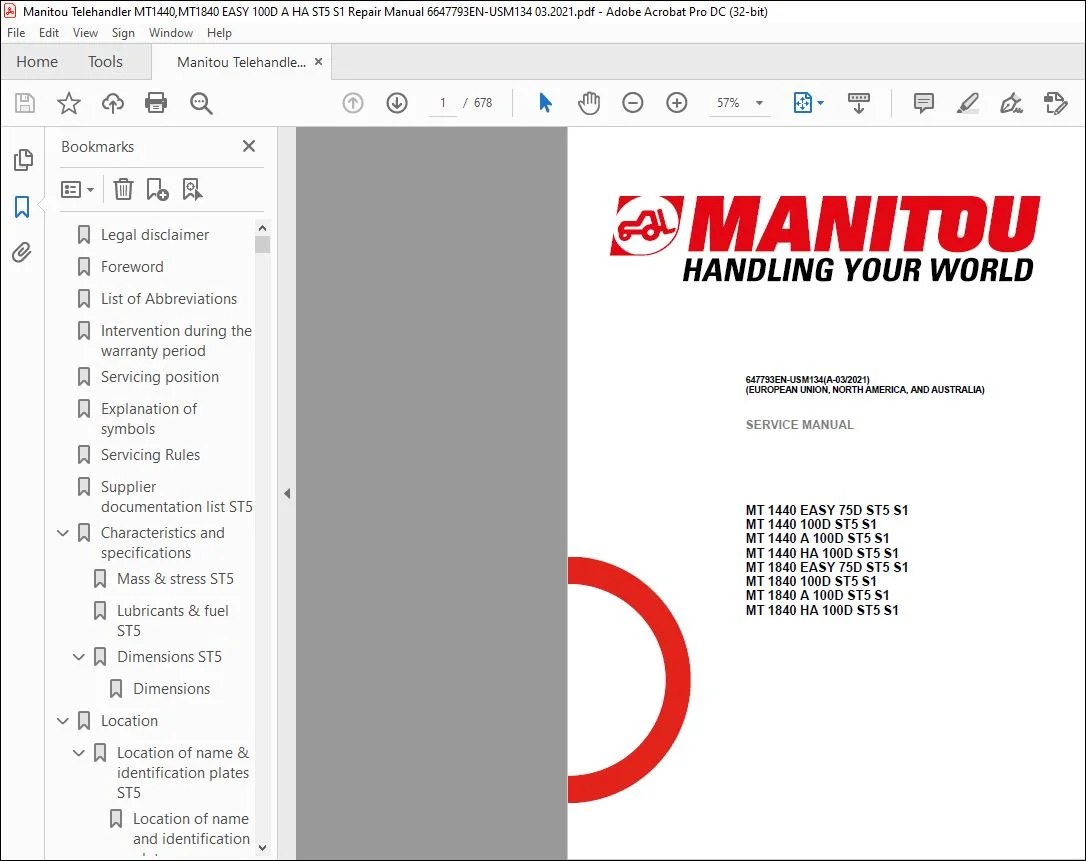
MT 1440 EASY 75D ST5 S1
MT 1440 100D ST5 S1
MT 1440 A 100D ST5 S1
MT 1440 HA 100D ST5 S1
MT 1840 EASY 75D ST5 S1
MT 1840 100D ST5 S1
MT 1840 A 100D ST5 S1
MT 1840 HA 100D ST5 S1
distribution, etc., in whole or in part, in any format whatsoever, is prohibited. The diagrams, drawings, images,
comments and indications found in this documentation, and the organization of the document itself, are intellectual
property of MANITOU BF. Any violation of the above is subject to civil and criminal penalties. The logos and visual
identity of the company are property of MANITOU BF and may not be used without express formal authorization. All
rights reserved.
Any reproduction, source code access, decompilation, modification, copy (other than backup copies), correction of
errors, transmission or distribution of any software built into Manitou machines is strictly prohibited.
In the event that the measures above nevertheless prove essential to enable use of the software, in accordance
with its destination, or to obtain the information required for interoperability with other software created
independently, the user should contact Manitou in advance and may, at its sole discretion, take the necessary
measures or give access to only the information strictly necessary for interoperability.
Any breach of these requirements is likely to constitute a counterfeiting offense subject to legal action by Manitou.
Connected Manitou machines are equipped with boxes that collect technical data on the machines (such as geotracking
data or data on component operation). This data, which is organized, processed and enhanced by
algorithms and expertise proprietary to Manitou, constitutes a protected database under Article L.341-1 of the
Intellectual Property Code.
It is strictly forbidden to have access to all or part of this database and to use the data (including in the event of
accidental access) without explicit prior authorization from Manitou. In the event that Manitou authorizes a Manitou
machine user to access all or part of this database, Manitou, as producer of this database, cedes to the user only a
right to personal, non-exclusive, nontransferable use of the database, and only by access to an information
technology platform hosted by a server owned or controlled by Manitou.
TABLE OF CONTENTS:
Manitou Telehandler MT1440,MT1840 EASY 100D A HA ST5 S1 Repair Manual 6647793EN – PDF DOWNLOAD
00. GENERAL AND SAFETY CHARACTERISTICS 13
00.1. FOREWORD…………………………………………………………………………………………………………………. 13
00.2. LIST OF ABBREVIATIONS…………………………………………………………………………………………… 13
00.3. WORK DURING THE WARRANTY PERIOD ……………………………………………………………….. 15
00.4. MAINTENANCE POSITION………………………………………………………………………………………….. 15
00.5. EXPLANATION OF SYMBOLS…………………………………………………………………………………….. 15
00.6. MAINTENANCE RULES ………………………………………………………………………………………………. 16
00.7. LIST OF SUPPLIER DOCUMENTATION ……………………………………………………………………… 19
00.8. CHARACTERISTICS AND SPECIFICATIONS …………………………………………………………….. 19
00.8.1 Weights and forces …………………………………………………………………………………………………………….19
00.8.2 Lubricants and fuels ……………………………………………………………………………………………………………20
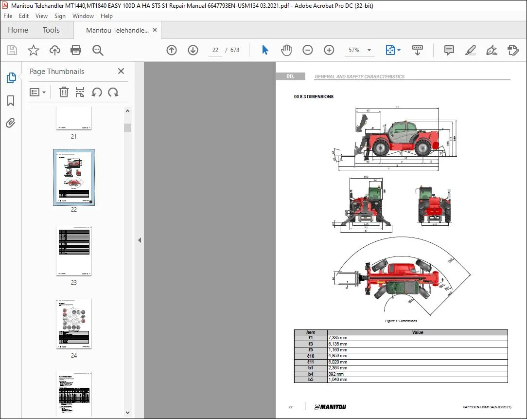
00.8.3 Dimensions ………………………………………………………………………………………………………………………22
00.9. LOCATION……………………………………………………………………………………………………………………. 24
00.9.1 Location of name and identification plates………………………………………………………………………………..24
00.10. CONTROL AND ADJUSTMENT ………………………………………………………………………………… 25
00.10.1 Standard tightening torques ………………………………………………………………………………………………..25
00.10.2 Metric – imperial unit conversion …………………………………………………………………………………………..26
10. ENGINE 28
10.1. CHARACTERISTICS AND SPECIFICATIONS …………………………………………………………….. 28
10.1.1 Supplier Documentation ………………………………………………………………………………………………………28
10.1.2 Fan control and reversal (HA versions) ……………………………………………………………………………………28
10.1.3 Conditions of fan control components ……………………………………………………………………………………..28
10.1.4 75D versions …………………………………………………………………………………………………………………….30
10.1.5 100D versions …………………………………………………………………………………………………………………..30
10.2. DIAGRAMS AND SCHEMATICS………………………………………………………………………………….. 31
10.2.1 Intake system and EGR……………………………………………………………………………………………………….31
10.2.2 Lubrication system ……………………………………………………………………………………………………………..32
10.2.3 Cooling system ………………………………………………………………………………………………………………….33
10.2.4 Fuel system………………………………………………………………………………………………………………………34
10.3. LOCATION……………………………………………………………………………………………………………………. 36
10.3.1 75D versions …………………………………………………………………………………………………………………….36
10.3.2 100D versions …………………………………………………………………………………………………………………..39
10.3.3 All versions……………………………………………………………………………………………………………………….41
4 647793EN-USM134(A-03/2021)
TABLE OF CONTENTS
10.4. CONTROL AND ADJUSTMENT…………………………………………………………………………………… 42
10.4.1 75D versions …………………………………………………………………………………………………………………….42
10.4.2 100D versions …………………………………………………………………………………………………………………..43
10.4.3 All versions……………………………………………………………………………………………………………………….45
10.5. REMOVAL…………………………………………………………………………………………………………………….. 50
10.5.1 75D versions …………………………………………………………………………………………………………………….50
10.5.2 100D versions …………………………………………………………………………………………………………………..56
10.5.3 All versions……………………………………………………………………………………………………………………….66
10.6. REFIT……………………………………………………………………………………………………………………………. 72
10.6.1 Refitting the 100D exhaust line………………………………………………………………………………………………72
10.6.2 Perform checks after refitting engine……………………………………………………………………………………….72
10.7. TROUBLESHOOTING………………………………………………………………………………………………….. 72
10.7.1 Engine assembly error codes………………………………………………………………………………………………..72
10.7.2 Ignition switching test ………………………………………………………………………………………………………….72
10.7.3 Engine start-up authorization conditions ………………………………………………………………………………….73
10.7.4 Lack of engine power ………………………………………………………………………………………………………….73
10.7.5 Fault table ………………………………………………………………………………………………………………………..73
10.8. SPECIFIC TOOLING…………………………………………………………………………………………………….. 76
10.8.1 DEF flush kit ……………………………………………………………………………………………………………………..76
10.8.2 Electronic belt tensiometer……………………………………………………………………………………………………76
20. TRANSMISSION 77
20.1. CHARACTERISTICS AND SPECIFICATIONS …………………………………………………………….. 77
20.1.1 Supplier Documentation ………………………………………………………………………………………………………77
20.2. DIAGRAMS AND SCHEMATICS………………………………………………………………………………….. 77
20.2.1 Mechanical transmission ……………………………………………………………………………………………………..77
20.2.2 Hydrostatic transmission (HA versions)……………………………………………………………………………………81
20.3. LOCATION……………………………………………………………………………………………………………………. 95
20.3.1 Mechanical transmission ……………………………………………………………………………………………………..95
20.3.2 Hydrostatic transmission (HA versions)……………………………………………………………………………………98
20.4. CONTROL AND ADJUSTMENT………………………………………………………………………………….101
20.4.1 Mechanical transmission …………………………………………………………………………………………………… 101
TABLE OF CONTENTS
647793EN-USM134(A-03/2021) 5
20.4.2 Hydrostatic transmission (HA versions)…………………………………………………………………………………. 104
20.5. REMOVAL…………………………………………………………………………………………………………………… 115
20.5.1 Mechanical transmission …………………………………………………………………………………………………… 115
20.5.2 Hydrostatic transmission (HA versions)…………………………………………………………………………………. 122
20.6. TROUBLESHOOTING…………………………………………………………………………………………………127
20.6.1 General authorization conditions for carriage movement …………………………………………………………… 127
20.6.2 Transmission DTC error codes……………………………………………………………………………………………. 127
20.7. SPECIFIC TOOLING……………………………………………………………………………………………………128
20.7.1 Basic manometer box……………………………………………………………………………………………………….. 128
20.7.2 Digital manometer box………………………………………………………………………………………………………. 128
20.7.3 Machined 50 mm socket……………………………………………………………………………………………………. 128
30. AXLE 130
30.1. CHARACTERISTICS AND SPECIFICATIONS ……………………………………………………………130
30.1.1 Supplier Documentation ……………………………………………………………………………………………………. 130
30.2. CONTROL AND ADJUSTMENT………………………………………………………………………………….130
30.2.1 Bleeding the axle locking cylinder………………………………………………………………………………………… 130
30.2.2 Adjusting the axle stops when installing wider tires ………………………………………………………………….. 130
40. BRAKE 133
40.1. CHARACTERISTICS AND SPECIFICATIONS ……………………………………………………………133
40.1.1 Specifications of the master cylinder…………………………………………………………………………………….. 133
40.1.2 Service brake specifications……………………………………………………………………………………………….. 133
40.1.3 Parking brake specifications ………………………………………………………………………………………………. 133
40.2. DIAGRAMS AND SCHEMATICS…………………………………………………………………………………135
40.2.1 Mechanical transmission …………………………………………………………………………………………………… 135
40.2.2 Hydrostatic transmission (HA versions)…………………………………………………………………………………. 137
40.3. LOCATION…………………………………………………………………………………………………………………..139
40.3.1 Location of service brake components ………………………………………………………………………………….. 139
6 647793EN-USM134(A-03/2021)
TABLE OF CONTENTS
40.4. CONTROL AND ADJUSTMENT………………………………………………………………………………….140
40.4.1 Mechanical transmission …………………………………………………………………………………………………… 140
40.4.2 Hydrostatic transmission (HA versions)…………………………………………………………………………………. 145
40.5. REMOVAL……………………………………………………………………………………………………………………146
40.5.1 Preparation and safety instructions before removal operations on the braking system. …………………….. 146
40.5.2 Removing the parking brake ………………………………………………………………………………………………. 147
40.5.3 Removing the master cylinder …………………………………………………………………………………………….. 147
40.5.4 Remove the braking assistance ………………………………………………………………………………………….. 148
40.6. SPECIFIC TOOLING……………………………………………………………………………………………………148
40.6.1 Hydraulic brake bleed valve ……………………………………………………………………………………………….. 148
40.6.2 Parking brake bleeder harness……………………………………………………………………………………………. 149
50. LIFT STRUCTURE 150
50.1. CHARACTERISTICS AND SPECIFICATIONS ……………………………………………………………150
50.1.1 Triplex boom MT 14 …………………………………………………………………………………………………………. 150
50.1.2 Quadruplex boom MT 18 …………………………………………………………………………………………………… 150
50.2. DIAGRAMS AND SCHEMATICS…………………………………………………………………………………150
50.2.1 Triplex 14 m boom kinematics …………………………………………………………………………………………….. 151
50.2.2 Quadruplex 18 m boom kinematics………………………………………………………………………………………. 153
50.3. LOCATION…………………………………………………………………………………………………………………..155
50.3.1 Location of components of 14 m triplex boom…………………………………………………………………………. 157
50.3.2 Location of 18 m quadruplex boom components……………………………………………………………………… 159
50.4. CONTROL AND ADJUSTMENT………………………………………………………………………………….161
50.4.1 Triplex boom…………………………………………………………………………………………………………………… 161
50.4.2 Quadruplex boom ……………………………………………………………………………………………………………. 167
50.5. REMOVAL……………………………………………………………………………………………………………………174
50.5.1 Triplex boom…………………………………………………………………………………………………………………… 174
50.5.2 Quadruplex boom ……………………………………………………………………………………………………………. 184
50.6. REFIT…………………………………………………………………………………………………………………………..200
50.6.1 Triplex boom…………………………………………………………………………………………………………………… 200
50.6.2 Quadruplex boom ……………………………………………………………………………………………………………. 208
TABLE OF CONTENTS
647793EN-USM134(A-03/2021) 7
50.7. SPECIFIC TOOLING……………………………………………………………………………………………………221
50.7.1 Pipe end pieces ………………………………………………………………………………………………………………. 221
50.7.2 Channel lever …………………………………………………………………………………………………………………. 221
50.7.3 Hose routing support ………………………………………………………………………………………………………… 222
50.7.4 Hose tension adjustment gage ……………………………………………………………………………………………. 223
50.7.5 Chain checking gage………………………………………………………………………………………………………… 223
70. HYDRAULICS 224
70.1. CHARACTERISTICS AND SPECIFICATIONS ……………………………………………………………224
70.1.1 List of hydraulic sheets ……………………………………………………………………………………………………… 225
70.1.2 FP HP feed block + remote accumulator ……………………………………………………………………………….. 227
70.1.3 FP HP feed block + accumulator …………………………………………………………………………………………. 230
70.1.4 SD 8/7 9-component distributor…………………………………………………………………………………………… 234
70.1.5 SD 8/8 9-component distributor…………………………………………………………………………………………… 239
70.1.6 4-component electro-proportional distributor PVG100/32 ………………………………………………………….. 245
70.1.7 3-component deflector distributor ………………………………………………………………………………………… 257
70.1.8 Power-assisted brake master cylinder ………………………………………………………………………………….. 258
70.1.9 Regulated cooling engine PLM20.19 ……………………………………………………………………………………. 260
70.1.10 Regulated cooling engine with inversion PLM20.16 ……………………………………………………………….. 260
70.1.11 Hydraulic pump KP30.43 …………………………………………………………………………………………………. 261
70.1.12 Backup pump EP-45 ………………………………………………………………………………………………………. 264
70.1.13 Steering pump ………………………………………………………………………………………………………………. 265
70.1.14 3-position steering selector ………………………………………………………………………………………………. 267
70.1.15 Double safety valve ………………………………………………………………………………………………………… 267
70.1.16 Double safety valve ………………………………………………………………………………………………………… 268
70.1.17 Double safety valve ………………………………………………………………………………………………………… 268
70.1.18 Double safety valve ………………………………………………………………………………………………………… 269
70.1.19 Single pilot safety valve …………………………………………………………………………………………………… 270
70.1.20 Single pilot safety valve …………………………………………………………………………………………………… 272
70.1.21 Discharge valve VMS ……………………………………………………………………………………………………… 273
70.1.22 Discharge block valve……………………………………………………………………………………………………… 274
70.1.23 Compensating isolation valve……………………………………………………………………………………………. 275
70.1.24 Operation of the compensating isolation valve………………………………………………………………………. 276
70.1.25 Flow rate control valve…………………………………………………………………………………………………….. 277
70.1.26 Dynamic selection valve ………………………………………………………………………………………………….. 278
70.1.27 Ventilation cut-off electrovalve VEIC …………………………………………………………………………………… 279
70.2. DIAGRAMS AND SCHEMATICS…………………………………………………………………………………279
70.2.1 Hydraulic diagram – MT 1440 …………………………………………………………………………………………….. 281
70.2.2 Hydraulic diagram – MT 1840 …………………………………………………………………………………………….. 287
70.2.3 Hydraulic diagram – MT(-X) A 1440……………………………………………………………………………………… 293
8 647793EN-USM134(A-03/2021)
TABLE OF CONTENTS
70.2.4 Hydraulic diagram – MT(-X) A 1840……………………………………………………………………………………… 299
70.2.5 Hydraulic diagram – MT HA 1440 ………………………………………………………………………………………… 305
70.2.6 Hydraulic diagram – MT HA 1840 ………………………………………………………………………………………… 313
70.3. LOCATION…………………………………………………………………………………………………………………..321
70.3.1 Location of hydraulic components – MT 1440 EASY 75D ST5 ……………………………………………………. 321
70.3.2 Location of hydraulic components – MT 1440 100D ST5 …………………………………………………………… 323
70.3.3 Location of hydraulic components – MT 1440 A 100D ST5 ………………………………………………………… 325
70.3.4 Location of hydraulic components – MT 1440 HA 100D ST5………………………………………………………. 326
70.3.5 Location of hydraulic components – MT 1840 EASY 75D ST5 ……………………………………………………. 329
70.3.6 Location of hydraulic components – MT 1840 100D ST5 …………………………………………………………… 331
70.3.7 Location of hydraulic components – MT 1840 A 100D ST5 ………………………………………………………… 333
70.3.8 Location of hydraulic components – MT 1840 HA 100D ST5………………………………………………………. 334
70.3.9 Location of central greasing system lubricators ………………………………………………………………………. 336
70.4. CONTROL AND ADJUSTMENT………………………………………………………………………………….337
70.4.1 Accumulation of the flow rates of the discharge valve (Access versions)……………………………………….. 337
70.4.2 Adjustment of the hydraulic circuit pressure connectors (non-Access versions)………………………………. 337
70.4.3 Adjustment of the hydraulic circuit pressure connectors (Access versions) ……………………………………. 338
70.4.4 Bleed the compensation/tilting circuit……………………………………………………………………………………. 338
70.4.5 Test the load holding capacity of the counterbalance valves of the cylinders (Access versions
only) ……………………………………………………………………………………………………………………… 339
70.4.6 Check the service brake hydraulic circuit on the FP HP feed block ………………………………………………. 344
70.4.7 9-component main hydraulic distributor tightening torques (14 m non-Access versions) …………………… 345
70.4.8 9-component main hydraulic distributor tightening torques (18 m non-Access versions) …………………… 346
70.4.9 4-component electro-proportional main hydraulic distributor tightening torques (Access
versions) ………………………………………………………………………………………………………………… 347
70.4.10 Leveling/stabilizer 3-component hydraulic distributor tightening torques (Access versions) ……………… 348
70.4.11 Hydraulic pump tightening torques……………………………………………………………………………………… 348
70.4.12 Hydraulic suction assembly tightening torques ……………………………………………………………………… 349
70.4.13 Hydraulic return filter tightening torque………………………………………………………………………………… 349
70.4.14 Breather plug tightening torque …………………………………………………………………………………………. 349
70.4.15 Hydraulic tank sealing plug tightening torque………………………………………………………………………… 349
70.4.16 Backup hydraulic circuit tightening torques (Access versions)…………………………………………………… 350
70.4.17 Braking/steering hydraulic unit tightening torques (75D versions)………………………………………………. 350
70.4.18 Braking/steering hydraulic unit tightening torques (100D versions)…………………………………………….. 350
70.4.19 Return manifold tightening torques (mechanical transmission)………………………………………………….. 350
70.4.20 Main hydraulic circuit tightening torques (HA versions)……………………………………………………………. 351
70.4.21 Parking brake hydraulic components tightening torques (mechanical transmission) ………………………. 351
70.4.22 Parking brake hydraulic components tightening torques (hydrostatic transmission) ……………………….. 351
70.4.23 Stabilizer cylinder valve tightening torque…………………………………………………………………………….. 352
70.4.24 Lifting cylinder valve tightening torque ………………………………………………………………………………… 352
70.4.25 Telescopic boom cylinder valve tightening torque (all versions apart from A) ………………………………… 352
TABLE OF CONTENTS
647793EN-USM134(A-03/2021) 9
70.4.26 Telescopic boom cylinder valve tightening torque (A versions only) ……………………………………………. 352
70.5. REMOVAL……………………………………………………………………………………………………………………353
70.5.1 Preparing and securing the machine before removal of hydraulic components……………………………….. 353
70.5.2 Removing the hydraulic oil tank…………………………………………………………………………………………… 354
70.5.3 Remove the 9-component hydraulic distributor with mechanical controls (non-Access versions) ………… 356
70.5.4 Remove the 4-component electro-proportional hydraulic distributor (Access versions) …………………….. 358
70.6. SPECIFIC TOOLING……………………………………………………………………………………………………359
70.6.1 Basic manometer box……………………………………………………………………………………………………….. 359
70.6.2 Digital manometer box………………………………………………………………………………………………………. 359
80. ELECTRICITY 360
80.1. CHARACTERISTICS AND SPECIFICATIONS ……………………………………………………………360
80.1.1 Fuses and relays …………………………………………………………………………………………………………….. 360
80.1.2 ECU Inputs/Outputs …………………………………………………………………………………………………………. 362
80.1.3 Technical sheets for electrical components ……………………………………………………………………………. 383
80.2. DIAGRAMS AND SCHEMATICS…………………………………………………………………………………405
80.2.1 CAN and LIN operating diagram – mechanical transmission ………………………………………………………. 405
80.2.2 CAN and LIN operating diagram – hydrostatic transmission ……………………………………………………….. 406
80.2.3 Examples of coding on the wiring diagrams……………………………………………………………………………. 407
80.2.4 Cable marking on an electrical wiring harness ………………………………………………………………………… 408
80.2.5 Position by diagram – MT 100D …………………………………………………………………………………………… 408
80.2.6 Electrical diagrams – MT 100D ……………………………………………………………………………………………. 423
80.2.7 Position by diagram – MT A 100D ………………………………………………………………………………………… 447
80.2.8 Electrical diagrams – MT A 100D …………………………………………………………………………………………. 461
80.2.9 Position by diagram – MT HA 100D………………………………………………………………………………………. 485
80.2.10 Electrical diagrams – MT HA 100D ……………………………………………………………………………………… 499
80.3. LOCATION…………………………………………………………………………………………………………………..523
80.3.1 Location of electrical components – MT 75D ………………………………………………………………………….. 525
80.3.2 Location of electrical components – MT 100D ………………………………………………………………………… 541
80.3.3 Location of electrical components – MT A 100D………………………………………………………………………. 559
80.3.4 Location of electrical components – MT HA 100D ……………………………………………………………………. 579
80.4. CONTROL AND ADJUSTMENT………………………………………………………………………………….599
80.4.1 Checking aggravating hydraulic movement cut-off…………………………………………………………………… 599
80.4.2 Adjust the longitudinal stability limiter and warning device …………………………………………………………. 599
80.4.3 Adjust the boom angular sensor ………………………………………………………………………………………….. 600
10 647793EN-USM134(A-03/2021)
TABLE OF CONTENTS
80.5. REMOVAL……………………………………………………………………………………………………………………600
80.5.1 Remove cab fuse and relay access panel ……………………………………………………………………………… 600
80.5.2 Remove engine fuse and relay access cover………………………………………………………………………….. 601
80.5.3 Removing the engine ECU…………………………………………………………………………………………………. 601
80.5.4 Removing the cab ECU …………………………………………………………………………………………………….. 602
80.5.5 Removing the instrument panel…………………………………………………………………………………………… 602
80.5.6 Removing the strain gage ………………………………………………………………………………………………….. 602
80.5.7 Removing the BMEP JSM …………………………………………………………………………………………………. 603
80.6. REFIT…………………………………………………………………………………………………………………………..603
80.6.1 Refitting the strain gage…………………………………………………………………………………………………….. 603
80.6.2 Refit the JSM on BMEP …………………………………………………………………………………………………….. 606
80.7. TROUBLESHOOTING…………………………………………………………………………………………………607
80.7.1 DTC Main ECU (SPU 40-26)………………………………………………………………………………………………. 607
80.7.2 DTC auxiliary ECU (SPU 25-15-STD2) or (SPU 40-26 PWM) …………………………………………………….. 616
80.7.3 Engine error code ……………………………………………………………………………………………………………. 622
80.7.4 Automatic air conditioning error codes ………………………………………………………………………………….. 643
80.8. SPECIFIC TOOLING……………………………………………………………………………………………………644
80.8.1 Electrovalve adapter ………………………………………………………………………………………………………… 644
80.8.2 Breakout boxes……………………………………………………………………………………………………………….. 644
85. OPERATOR STATION 645
85.1. CHARACTERISTICS AND SPECIFICATIONS ……………………………………………………………645
85.1.1 Description of air conditioning operation………………………………………………………………………………… 645
85.1.2 Safety measures for handling R134a ……………………………………………………………………………………. 645
85.2. DIAGRAMS AND SCHEMATICS…………………………………………………………………………………646
85.2.1 Schematic diagrams…………………………………………………………………………………………………………. 646
85.3. LOCATION…………………………………………………………………………………………………………………..648
85.3.1 HVAC components…………………………………………………………………………………………………………… 648
85.3.2 Automatic air conditioning location ………………………………………………………………………………………. 650
85.3.3 Condenser component ……………………………………………………………………………………………………… 651
85.4. CONTROL AND ADJUSTMENT………………………………………………………………………………….651
85.4.1 General checkpoints ………………………………………………………………………………………………………… 651
85.4.2 Air conditioning assembly instructions ………………………………………………………………………………….. 652
TABLE OF CONTENTS
647793EN-USM134(A-03/2021) 11
85.4.3 Safety measures for handling R134a ……………………………………………………………………………………. 652
85.4.4 Check the evaporator temperature sensor …………………………………………………………………………….. 652
85.4.5 Cab air conditioning tightening torques …………………………………………………………………………………. 655
85.4.6 Cab suspension silent block tightening torques ………………………………………………………………………. 656
85.5. REMOVAL……………………………………………………………………………………………………………………656
85.5.1 Removing the lower dashboard trim panel …………………………………………………………………………….. 656
85.5.2 Removing the front cab casing ……………………………………………………………………………………………. 657
85.5.3 Removing the rear cab casing…………………………………………………………………………………………….. 657
85.5.4 Removing the air conditioning heating unit …………………………………………………………………………….. 657
85.5.5 Removing the cab ……………………………………………………………………………………………………………. 658
85.5.6 Removing the condenser…………………………………………………………………………………………………… 664
85.5.7 Removing the motor and electric window ………………………………………………………………………………. 664
85.6. REFIT…………………………………………………………………………………………………………………………..666
85.6.1 Refitting the motor and electric window …………………………………………………………………………………. 666
85.7. TROUBLESHOOTING…………………………………………………………………………………………………667
85.7.1 Automatic air conditioning error codes ………………………………………………………………………………….. 667
85.7.2 Temperature fault…………………………………………………………………………………………………………….. 667
85.7.3 Unusual noise…………………………………………………………………………………………………………………. 668
85.7.4 Unpleasant smell …………………………………………………………………………………………………………….. 668
90. CHASSIS 669
90.1. CONTROL AND ADJUSTMENT………………………………………………………………………………….669
90.1.1 Counterweight tightening torque………………………………………………………………………………………….. 669
90.2. REMOVAL……………………………………………………………………………………………………………………669
90.2.1 Remove the engine hood…………………………………………………………………………………………………… 669
90.2.2 Remove the 75D engine housing…………………………………………………………………………………………. 670
90.2.3 Remove the 100D engine housing……………………………………………………………………………………….. 671
110. ADDITIONAL EQUIPMENT 673
120. DIAGNOSTIC TOOLS AND SOFTWARE 674
120.1. DIAGNOSTICS CASE KIT…………………………………………………………………………………………674
120.2. USB LINK 2 BOX ………………………………………………………………………………………………………675
120.3. COMPONENT DIAGNOSTICS BOX………………………………………………………………………….676
PLEASE NOTE:
- This is not a physical manual but a digital manual – meaning no physical copy will be couriered to you. The manual can be yours in the next 2 mins as once you make the payment, you will be directed to the download page IMMEDIATELY.
- This is the same manual used by the dealers inorder to diagnose your vehicle of its faults.
- Require some other service manual or have any queries: please WRITE to us at [email protected]
S.V