Manitou Work Platform 160 ATJ 4RD ST5 S2 160 ATJ RC 4RD ST5 S2 180 ATJ 4RD ST5 S2 180 ATJ RC 4RD ST5 S2 Service Manual 647951 – PDF DOWNLOAD
Original price was: $89.95.$28.95Current price is: $28.95.
Manitou Work Platform 160 ATJ 4RD ST5 S2 160 ATJ RC 4RD ST5 S2 180 ATJ 4RD ST5 S2 180 ATJ RC 4RD ST5 S2 Service Manual 647951 – PDF DOWNLOAD
Description
Manitou Work Platform 160 ATJ 4RD ST5 S2 160 ATJ RC 4RD ST5 S2 180 ATJ 4RD ST5 S2 180 ATJ RC 4RD ST5 S2 Service Manual 647951 – PDF DOWNLOAD
IMAGES PREVIEW OF THE MANUAL:
DESCRIPTION:
Manitou Work Platform 160 ATJ 4RD ST5 S2 160 ATJ RC 4RD ST5 S2 180 ATJ 4RD ST5 S2 180 ATJ RC 4RD ST5 S2 Service Manual 647951 – PDF DOWNLOAD
GENERAL AND SAFETY CHARACTERISTICS:
FOREWORD:
This chapter deals with the general instructions and safety notice during servicing checks and work. The
other instructions and warning texts are indicated in the chapters concerned.
In order to reduce the risk of accidents, please:
• Follow the instructions in the operator’s manual and the truck servicing instructions.
• > This manual should be found in all trucks.
• Please follow the safety instructions.
• Use the appropriate tools for all work to be carried out.
• Use original Manitou spare parts.
- If these instructions are not followed there is a risk of accidents occurring, the severity of which could go as
far as causing death. - A person who follows the safety instructions and a wellserviced machine make a safe, effective and profitable
combination.
TABLE OF CONTENTS:
Manitou Work Platform 160 ATJ 4RD ST5 S2 160 ATJ RC 4RD ST5 S2 180 ATJ 4RD ST5 S2 180 ATJ RC 4RD ST5 S2 Service Manual 647951 – PDF DOWNLOAD
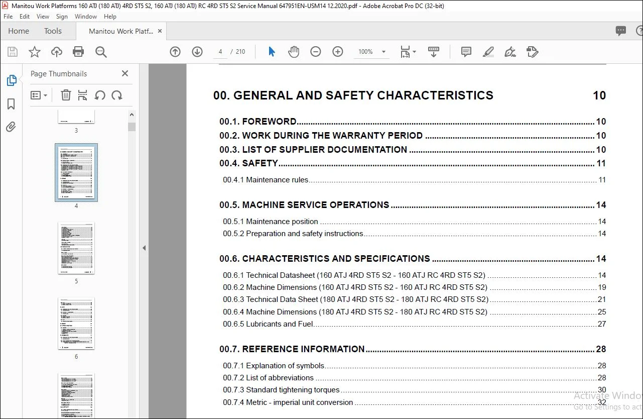
00 GENERAL AND SAFETY CHARACTERISTICS 10
00 1 FOREWORD 10
00 2 WORK DURING THE WARRANTY PERIOD 10
00 3 LIST OF SUPPLIER DOCUMENTATION 10
00 4 SAFETY 11
00 4 1 Maintenance rules 11
00 5 MACHINE SERVICE OPERATIONS 14
00 5 1 Maintenance position 14
00 5 2 Preparation and safety instructions 14
00 6 CHARACTERISTICS AND SPECIFICATIONS 14
00 6 1 Technical Datasheet (160 ATJ 4RD ST5 S2 – 160 ATJ RC 4RD ST5 S2) 14
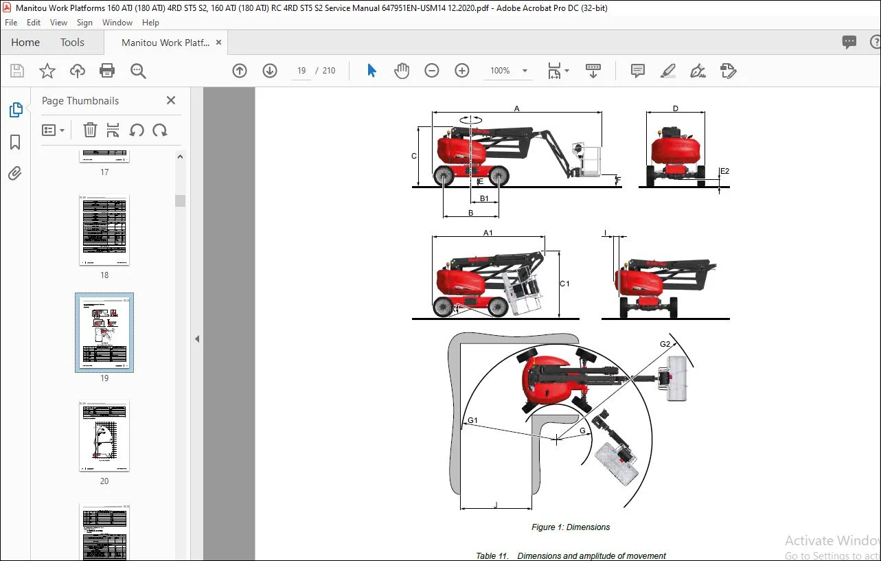
00 6 2 Machine Dimensions (160 ATJ 4RD ST5 S2 – 160 ATJ RC 4RD ST5 S2) 19
00 6 3 Technical Data Sheet (180 ATJ 4RD ST5 S2 – 180 ATJ RC 4RD ST5 S2) 21
00 6 4 Machine Dimensions (180 ATJ 4RD ST5 S2 – 180 ATJ RC 4RD ST5 S2) 25
00 6 5 Lubricants and Fuel 27
00 7 REFERENCE INFORMATION 28
00 7 1 Explanation of symbols 28
00 7 2 List of abbreviations 28
00 7 3 Standard tightening torques 30
00 7 4 Metric – imperial unit conversion 32
10 ENGINE 34
10 1 CHARACTERISTICS AND SPECIFICATIONS 34
10 1 1 Supplier Documentation 34
10 1 2 Specifications of the D1105-E4B engine 34
10 2 LOCATION 35
10 2 1 Location of engine components 35
10 2 2 Location of Diesel Fuel Circuit Components 36
10 3 CONTROL AND ADJUSTMENT 37
10 3 1 Engine Tightening Torques 37
10 3 2 Engine Speed Block Adjustment 37
10 3 3 Adjust the alternator belt tension 38
4 647951EN-USM14(A-12/2020)
TABLE OF CONTENTS
10 4 REMOVAL 38
10 4 1 Placing the strut 38
10 4 2 Removing the engine access covers 39
10 4 3 Removing the cooling system 39
10 4 4 Removing the muffler 41
10 4 5 Removing the harnesses 41
10 4 6 Removing the air intake circuit 42
10 4 7 Removing the diesel circuit 42
10 4 8 Removing the hoses from the hydrostatic and auxiliary pumps 43
10 4 9 Removing the engine speed block 43
10 4 10 Remove the engine 44
10 5 REFIT 44
10 5 1 Refitting the engine 44
10 6 TROUBLESHOOTING 45
10 6 1 Troubleshooting 45
10 6 2 Kubota Engine Fault Codes D1105–E4B 47
20 TRANSMISSION 48
20 1 CHARACTERISTICS AND SPECIFICATIONS 48
20 1 1 Supplier Documentation 48
20 2 LOCATION 48
20 2 1 Transmission Components Location 49
20 3 CONTROL AND ADJUSTMENT 51
20 3 1 Transmission tightening torques 51
20 3 2 Location of pressure connectors (Rexroth A10VG pump) 52
20 3 3 Location of adjustment points (Rexroth A10VG pump) 53
20 3 4 Calibration of the LP Booster Valve 53
20 3 5 Neutral point adjustment – servo-control piston 54
20 3 6 Calibration – HP Valves 54
20 3 7 Calibration – Zero flow valve DR 55
20 4 REMOVAL 56
20 4 1 Removing the Hydrostatic Pump 56
20 4 2 Removing the Hydrostatic Motor 57
TABLE OF CONTENTS
647951EN-USM14(A-12/2020) 5
20 5 REFIT 58
20 5 1 Refitting the hydrostatic pump 58
20 5 2 Refitting the Hydrostatic Motor 58
30 AXLE 59
30 1 CHARACTERISTICS AND SPECIFICATIONS 59
30 1 1 Supplier Documentation 59
30 2 CONTROL AND ADJUSTMENT 59
30 2 1 Freewheeling mode 59
30 3 REMOVAL 60
30 3 1 Removing the Front Axle 60
30 3 2 Removing the Rear Axle 62
30 4 REFIT 63
30 4 1 Refitting Front Axle and Rear Axle 63
40 BRAKE 69
50 LIFTING STRUCTURE 70
50 1 REMOVAL 70
50 1 1 Removing the telescoping cylinder slide pads 70
50 1 2 Remove the pads from arm 3 70
50 1 3 Removing the pads from the moving tube cylinder 70
50 1 4 Remove the basket 71
50 1 5 Removing the jib 73
70 HYDRAULICS 75
70 1 CHARACTERISTICS AND SPECIFICATIONS 75
70 1 1 Supplier Documentation 75
70 2 FLOW DIAGRAMS AND SCHEMATIC DIAGRAMS 75
70 2 1 Hydraulic diagram (ATJ 46 T4 S2 — 160 ATJ 4RD ST5 S2 – 160 ATJ RC 4RD ST5 S2 — 180 ATJ
4RD ST5 S2 – 180 ATJ RC 4RD ST5 S2) 77
6 647951EN-USM14(A-12/2020)
TABLE OF CONTENTS
70 3 LOCATION 81
70 3 1 Location of hydraulic components in chassis 83
70 3 2 Location of hydraulic components in the turntable 85
70 3 3 Location of hydraulic components in the arms 87
70 4 CONTROL AND ADJUSTMENT 89
70 4 1 Prerequisite for proportional valve group calibration 89
70 4 2 Proportional valve group calibration 89
70 4 3 Distributor Block calibration 91
70 4 4 Compensating and tilting circuit 93
70 5 REMOVAL 95
70 5 1 Remove the elements of the proportional valve group 95
70 5 2 Removing the distributor block 95
70 5 3 Removing a valve from the Distributor block 96
70 5 4 Preparing for cylinder removal 97
70 5 5 Decompressing the hoses 98
70 5 6 Removing the cylinders 99
70 5 7 Removing valve blocks and valves 100
70 6 REFIT 101
70 6 1 Refitting a valve on the Distributor block 101
70 6 2 Reinstall the cylinders 103
70 7 SPECIFIC TOOLING 104
70 7 1 Digital manometer box 104
70 7 2 Basic manometer box 105
80 ELECTRICITY 106
80 1 CHARACTERISTICS AND SPECIFICATIONS 106
80 1 1 Fuses and relays 106
80 2 FLOW DIAGRAMS AND SCHEMATIC DIAGRAMS 108
80 2 1 Examples of coding on the wiring diagrams 108
80 2 2 Cable marking on an electrical wiring harness 109
80 2 3 Electrical diagrams (ATJ 46 T4 S2 — 160 ATJ 4RD ST5 S2 – 160 ATJ RC 4RD ST5 S2 — 180 ATJ
4RD ST5 S2 – 180 ATJ RC 4RD ST5 S2) 111
TABLE OF CONTENTS
647951EN-USM14(A-12/2020) 7
80 3 LOCATION 127
80 3 1 Location of electrical control components 129
80 3 2 Location of electrical power components 131
80 3 3 Option electrical components location 133
80 3 4 Location of Harnesses 135
80 3 5 Locations of controls, base control panel indicator lamps 147
80 3 6 Location of controls, indicators of the basket control panel and wiring 153
80 4 CONTROL AND ADJUSTMENT 163
80 4 1 Program Operation 163
80 4 2 Program Parameters 166
80 4 3 Joystick Calibration 180
80 4 4 Joystick Testing 181
80 4 5 Telescope Retracted Sensor Adjustment 181
80 4 6 Arm Down Sensor Adjustment 182
80 4 7 Tilt Calibration 182
80 4 8 Overload Sensor Adjustment 183
80 4 9 Maximum Movement Speed Calibration 184
80 4 10 Generator Setting (optional) 185
80 4 11 Stop&Go option management 186
80 5 REMOVAL 187
80 5 1 Remove the board UC234 from the base control panel 187
80 5 2 Remove board UD22 from the base control panel 188
80 6 TROUBLESHOOTING 190
80 6 1 Fault Codification 190
80 6 2 Warning and Fault code list 192
80 7 SPECIFIC TOOLING 194
80 7 1 Breakout boxes 194
85 OPERATOR STATION 195
90 CHASSIS 196
90 1 CONTROL AND ADJUSTMENT 196
90 1 1 Check slewing ring gear play 196
8 647951EN-USM14(A-12/2020)
TABLE OF CONTENTS
110 ADDITIONAL EQUIPMENT 198
120 DIAGNOSTIC TOOLS AND SOFTWARE 199
120 1 KUBOTA ENGINE FAULT CODES D1105–E4B 199
120 2 KUBOTA ENGINE FAULT CODES AFTER TREATMENT D1105–E4B 204
120 3 REPROGRAMMING CASE (MEWP) 205
Customer Support: [email protected]
PLEASE NOTE:
- This is the SAME MANUAL used by the dealerships to diagnose your vehicle
- No waiting for couriers / posts as this is a PDF manual and you can download it within 2 minutes time once you make the payment.
- Your payment is all safe and the delivery of the manual is INSTANT – You will be taken to the DOWNLOAD PAGE.
- So have no hesitations whatsoever and write to us about any queries you may have : heydownloadss @gmail.com
S.V