Manitowoc Crane 12000 Operator’s Manual SN 12005Ref – PDF DOWNLOAD
$27.95
Description
Manitowoc Crane 12000 Operator’s Manual SN 12005Ref – PDF DOWNLOAD
FILE DETAILS:
Manitowoc Crane 12000 Operator’s Manual SN 12005Ref – PDF DOWNLOAD
Language : English
Pages : 176
Downloadable : Yes
File Type : PDF
IMAGES PREVIEW OF THE MANUAL:
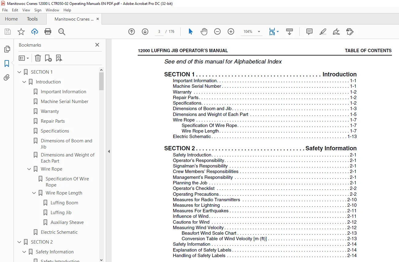
TABLE OF CONTENTS:
Manitowoc Crane 12000 Operator’s Manual SN 12005Ref – PDF DOWNLOAD
SECTION 1 5
Introduction 7
Important Information 7
Machine Serial Number 7
Warranty 8
Repair Parts 8
Specifications 8
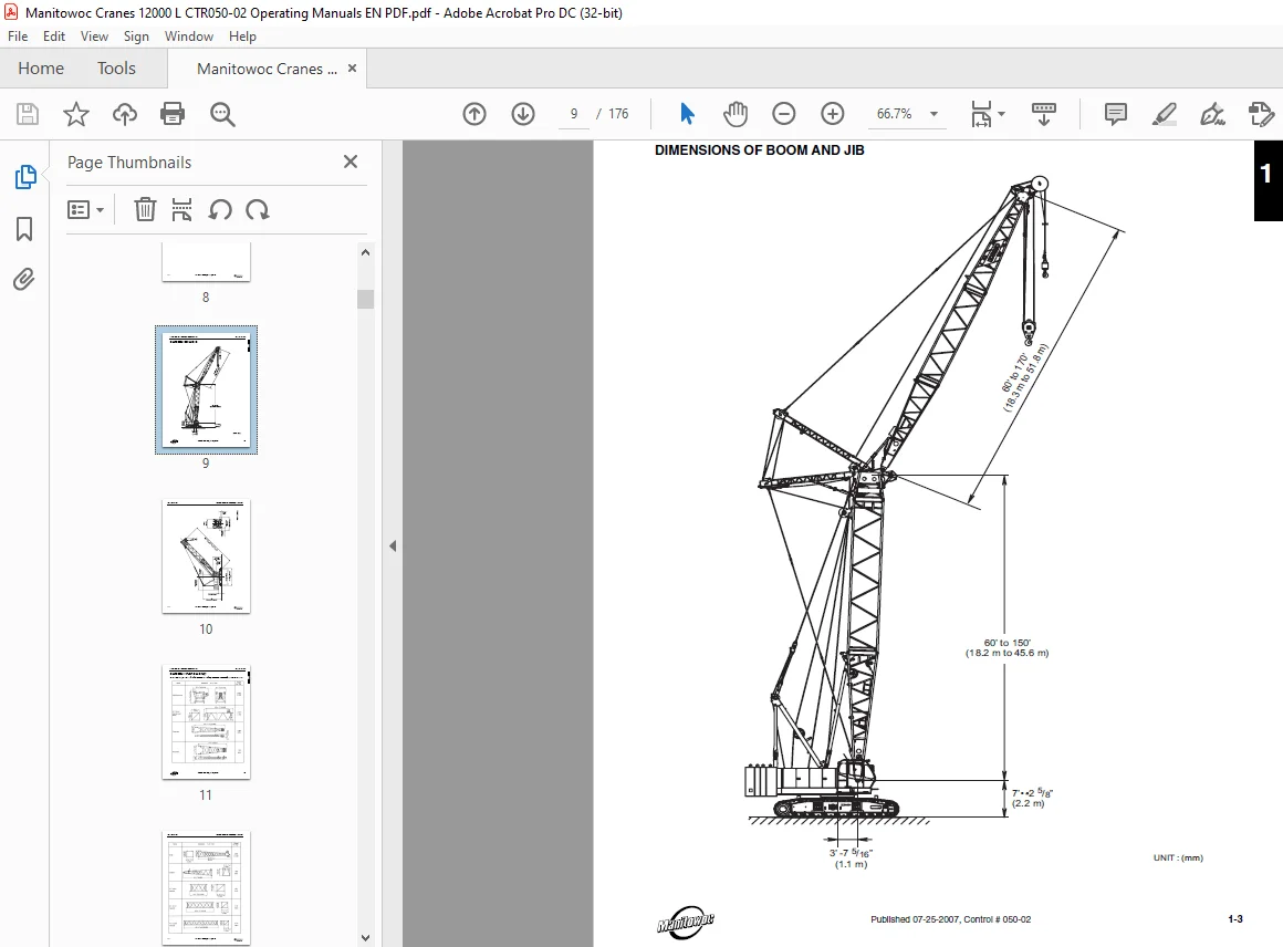
Dimensions of Boom and Jib 9
Dimensions and Weight of Each Part 11
Wire Rope 13
Specification Of Wire Rope 13
Wire Rope Length 13
Luffing Boom 13
Luffing Jib 14
Auxiliary Sheave 18
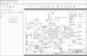
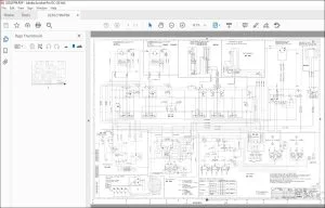
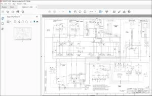
Electric Schematic 19
SECTION 2 31
Safety Information 35
Safety Introduction 35
Operator’s Responsibility 35
Signalman’s Responsibility 35
Crew Members’ Responsibilities 35
Management’s Responsibility 35
Planning the Job 35
Operator’s Checklist 36
Operating Precautions 36
Measures for Radio Transmitters 44
Measures for Lightning 44
Measures For Earthquakes 45
Influence of Wind 45
Cautions for Wind 46
Measuring Wind Velocity 46
Beaufort Wind Scale Chart 47
Conversion Table of Wind Velocity [m (ft)] 47
Safety Information 48
Explanation of Safety Labels 48
Handling of Safety Labels 48
SECTION 3 57
Operating Controls and Procedures 59
Luffing Jib Components 59
Identification and Location of Operating Controls 60
Operation of Switches 62
Luffing Jib Operation 62
Luffing Boom Raising/Lowering Operation 63
Jib Raising/Lowering Operation 64
Hook Raising/lowering Operation 64
Free Fall Operation 66
Load Safety Device 67
Equipment Arrangement 68
Luffing 68
Luffing Jib 69
Detail of Boom Overhoist Limit Switch 70
Luffing Boom 70
Luffing Jib 70
Equipment Type and Function 71
Controller/Monitor 71
Load Detector 72
Jib Load Detector 72
Boom Load Detector 72
Angle Detector 72
Backstop Limit Switches 73
Attachment Junction Panel 73
Luffing Cable Junction Box 74
Luffing Jib Overhoist Limit Switch 74
Hook Overhoist Limit Switch 75
Release Switch 75
Luffing Junction Cable 76
Cable Reel 76
Over Load Alarm Lamp (Option) 77
Connecting Procedure for Wiring 78
Luffing Attachment 78
Connecting Procedure 79
Connecting Attachment Harness To Body Harness 79
Connection of Cable at Cable Reel 80
Connection of Cables at Luffing Boom Tip 81
Connection of Cable at Luffing Jib Point 82
Function Of Controller/Monitor 83
Operating Procedure of Controller 87
Turning Power ON 87
Setting Screen 88
Setting The Crane Configuration 92
Select in order of number (a) to (h) 93
Selection of Main/Jib/Aux Lifting 96
For Crane 96
For Luffing 96
Setting of Working Area Limit Value 96
Warning Point and Stopping Point 98
When Canceling Input Halfway 99
When Limit Function Is Not Used 99
Setting the Time 99
Warning Alarm And Automatic Stop 101
Items of Warning Alarm and Automatic Stop 101
Luffing 101
Contents of Automatic Stop 101
Release of Automatic Stop 104
Automatic Stop Release Switch 104
Operation of Automatic Stop Release Switch 104
Boom Lowering Method at Out of Angle 105
Release of Automatic Stop When Assembling and Disassembling the Boom 107
Inspection 108
Inspection Before Raising The Boom After Assembly of Attachment Is Completed 108
Luffing Crane Attachment 109
Inspection After Erecting The Attachment 113
Caution for Handling the Load Safety Device 113
Indication of Errors and Remedy 113
Indication of Message and Alarm 114
Confirmation of Function for Load Safety Device 115
SECTION 4 117
Set-Up And Installation 119
General Set-up Instructions 119
Assembly of Luffing Attachment 119
Arrangement of Boom and Jib 120
Boom and Jib 120
Guy Line 121
Boom and Jib Arrangement Charts 122
Installing Luffing Jib Attachment 129
Remove Crane Boom and Guy LInes 133
Install Special Boom Insert with Idler Sheave 134
Caution for Cantilever 135
Support with Base Boom 135
Connect Luffing Boom Tip Assembly 135
Install Auxiliary Sheave 136
Assemble Jib 136
Install Strut Guy Line 137
Install Jib Hoist Wire Rope 139
Connect Strut Guy Line And Strut Backstop 140
Install Jib Guy Line 142
Reeve Front and Rear Drum Wire Rope 143
Reeving Diagrams 144
Connecting the Safety Device 146
Raising Luffing Jib Attachment 149
Pre-Raising Checks 149
Raising Procedure 150
Pre-Operation Check 152
Lowering Luffing Jib Attachment 152
Lowering Procedure 152
Removing Luffing Jib Attachment 155
Disconnect Safety Device Wiring 155
Store Front Drum and Rear Drum Wire Rope 156
Disassemble Jib 156
Remove Luffing Boom Tip Assembly 158
Disassemble Boom Inserts 160
Remove Base Boom 160
Caution When Transporting Luffing Boom Tip Assembly 160
SECTION 5 161
Lubrication 163
Attachment 165
Grease 165
Boom Foot Pin 165
Hydraulic Oil 166
Checking Hydraulic Oil Level 166
Changing Hydraulic Oil 166
SECTION 6 167
Maintenance Checks 169
General Maintenance 169
Inspection Tables 169
Maintenance Repairs or Adjustments 169
Maintenance 169
Parts 169
Precautions When Performing Inspections and Maintenance 169
Maintenance Checks 172
Customer Support: [email protected]
S.V