Manitowoc Crane MLC165-1 Operator Manual PDF
$28.95
The Manitowoc Crane MLC165-1 Operator Manual in PDF format is a vital resource for operating the MLC165-1 model crane. Download for comprehensive guidance on safe and efficient crane operation, including essential instructions and safety protocols.
Description
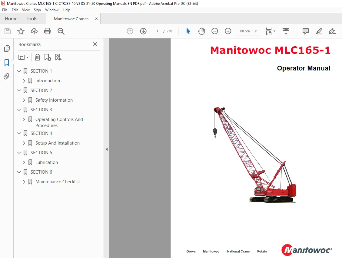
Manitowoc Crane MLC165-1 Operator Manual – PDF DOWNLOAD
FILE DETAILS:
Manitowoc Crane MLC165-1 Operator Manual – PDF DOWNLOAD
Language : English
Pages :256
Downloadable : Yes
File Type : PDF
IMAGES PREVIEW OF THE MANUAL:
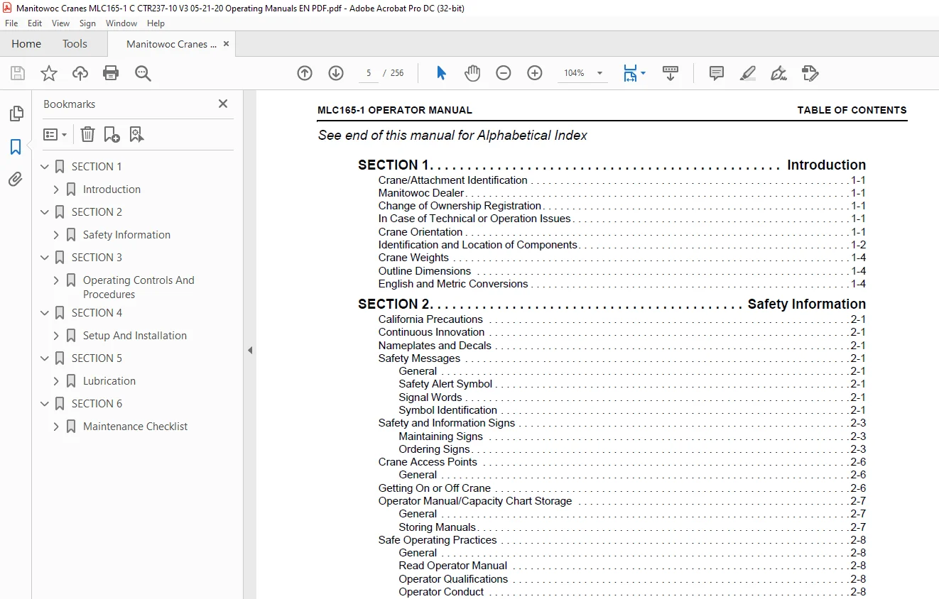
TABLE OF CONTENTS:
Manitowoc Crane MLC165-1 Operator Manual – PDF DOWNLOAD
SECTION 1 11
Introduction 13
Crane/Attachment Identification 13
Manitowoc Dealer 13
Change of Ownership Registration 13
In Case of Technical or Operation Issues 13
Crane Orientation 13
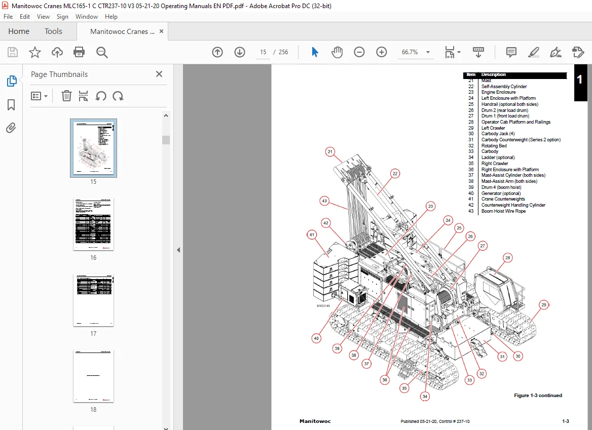
Identification and Location of Components 14
Crane Weights 16
Outline Dimensions 16
English and Metric Conversions 16
SECTION 2 19
Safety Information 21
California Precautions 21
Continuous Innovation 21
Nameplates and Decals 21
Safety Messages 21
General 21
Safety Alert Symbol 21
Signal Words 21
Symbol Identification 21
Safety and Information Signs 23
Maintaining Signs 23
Ordering Signs 23
Crane Access Points 26
General 26
Getting On or Off Crane 26
Operator Manual/Capacity Chart Storage 27
General 27
Storing Manuals 27
Safe Operating Practices 28
General 28
Read Operator Manual 28
Operator Qualifications 28
Operator Conduct 28
Handling Load 30
Signals 33
Safety Devices 34
Operational Aids 34
Category 1 Operational Aids 34
Category 2 Operational Aids 35
Assembling, Disassembling, or Operating Crane Near Electric Power and Transmission Lines 36
Electrocution Hazard 36
Set-Up and Operation 36
Electrocution Hazard Devices 37
Electrical Contact 37
Refueling 38
Fire Extinguishers 38
Accidents 38
Safe Maintenance 38
Maintenance Instructions 38
Safe Maintenance Practices 38
Environmental Protection 40
Boom Disassembly Safety 43
General 43
Location 43
Pin Removal 43
Disassembly Precaution 43
Personnel Handling Policy 44
Pedestal/Barge Mounted Cranes 45
Pedestal Mounted Crane 45
Barge Mounted Crane 46
Capacity Charts for Barge Mounted Cranes 47
Shock Loading Caused by Barge Dynamics 47
Operation on Barge 48
Barge Mount Definitions 48
Inspection of Barge Mounted Crane 48
Transporting Crane on Barge 48
SECTION 3 49
Operating Controls And Procedures 51
Cab Controls and Indicators 52
Left Console 56
Foot Pedals 59
Front Console 60
Right Console 64
Overhead Console 68
Seat Controls 71
Camera Controls 72
Bypassable Limits Identification 74
Handle-to-Drum Identification 75
Boom Angle Indicator 76
RCL/RCI Warning Light 76
Upperworks Bubble Level 76
Setup Controls 78
Remote Control 78
Carbody Controls 80
Operating Limits and Faults 81
Boom Max Up Limit 81
Minimum Bail Limit 81
Block-Up Limit 81
Mast Too Far Forward 81
Rated Capacity Limit 81
Main Display Information Screen 82
Engine Warning Lights and Fault Codes 83
Tier 4 Engine Faults 83
Emergency Cab Exit 84
Cab Ventilation 84
Operating in Wind 85
Crawler Blocking 85
Operating Procedures 85
Preparing the Crane for Operation 85
Startup Procedure 86
Boom Hoist (Drum 4) Operation 89
Swing Operation 90
Drum 1 and Drum 2 Full Power Operation 91
Drum 1 or Drum 2 Free Fall Operation 92
Clamshell Operation 94
Travel Operation 96
Crane Shutdown or Leaving the Crane Unattended 98
Cold Weather Operation 99
Crane Limitations 99
Wire Rope 99
Cold Weather Starting Aid 99
Cooling System 99
Batteries 99
Engine Oil, Gear Oil, and Hydraulic Oil 99
AC Electric System 101
Turning On AC Components 101
Turning Off AC Components 101
Cold Weather Heater Package 103
Standard Hand Signals for Controlling Crane Operations 104
Symbols Used on Control Consoles 106
SECTION 4 111
Setup And Installation 115
Lifting Assembly Drawing 115
Boom and Jib Assembly Drawings 115
General Safety 115
Crane Orientation 115
Assembly and Disassembly Notes 115
Assembly and Disassembly Area 116
Accessing Parts 116
Crane Weights and Shipping Data 116
Retaining Connecting Pins 116
Parts Boxes 116
Pin and Connecting Hole Cleanliness 116
Hose and Cable Cleanliness 117
Connecting/Disconnecting Hydraulic Hoses and Electric Cables 117
Self-Assembly Components 117
Load Sensing Pins 117
Self-Assembly Controls 119
Setup Mode 120
Crane Assembly 125
Remove Crane from Trailer 125
Remove Cab Window Covers 126
Deploy Operator Cab 126
Install RCL/RCI Indicator Light 127
Install Rotating Bed Mirror 127
Raise Handrails 129
Perform Pre-Start Checks 131
Start Engine 131
Prepare Mast for Raising 133
Raise Mast to Vertical 133
Mast Working Angles 135
Install Crawlers – Preliminary Steps 136
Install First Crawler 137
Finish Installing Crawlers 141
Install Upperworks Platform Sections 143
Install Carbody Counterweight (Series 2) 145
Assemble Crane Counterweight 147
Install Crane Counterweight 151
Install Counterweight Work Lights 153
Remove Boom Butt from Trailer 154
Raise Boom Butt Wire Rope Guide 154
Raise Boom Stops 154
Attached Boom Butt to Crane 157
Assemble Boom to Boom Butt 158
Connect Mast Straps to Boom Straps 160
Connect Electric Cables from Crane to Boom Butt 161
Connect Boom Butt Hydraulic Hoses 163
Complete Boom and Jib Assembly 163
Raise Boom 165
Pre-Raising Checks 165
Boom Raising Procedure 165
Shipping Crane Components 167
Crane Disassembly 167
Prepare Crane 167
Lower Boom 167
Remove Block-Up Limit Components 169
Store the Load Lines 169
Remove Boom Work Lights 169
Disconnect Boom Wiring 169
Disconnect Boom Butt Electric Cables 169
Disconnect Boom Butt Hydraulic Hoses 169
Disconnect Mast Straps from Boom Straps 171
Disconnect Boom Butt from Boom 173
Disassemble Boom from Boom Butt 173
Remove Boom Butt 175
Lower Boom Stops 177
Lower Boom Butt Wire Rope Guide 177
Lift Boom Butt onto Trailer 177
Store Counterweight Work Lights 177
Remove Crane Counterweight 179
Disassemble Crane Counterweight 183
Remove Carbody Counterweight (Series 2) 185
Remove Upperworks Platforms 187
Remove Crawlers – Preliminary Steps 189
Remove First Crawlers 191
Remove Second Crawler 193
Store Upperworks Platform Sections 193
Lower Mast to Transport Position 195
Lower Handrails 195
Remove or Store Rotating Bed Mirror 195
Store RCL/RCI Indicator Light 195
Stop Engine 195
Install Window Covers 195
Store Operator Cab 195
Install Crane from Trailer 197
Boom Ladders 199
Installing the Ladders 199
Storing the Ladders 199
Boom and Jib Rigging 200
Assist Crane Requirements 200
Blocked Crawlers 200
Boom Handling with Mast 200
Assembly Drawings 200
Identifying Boom and Jib Components 200
Handling Components 202
Boom #74A Assembly 205
Boom #74A Disassembly 217
Jib #134 Assembly 221
Jib #134 Disassembly 230
Wire Rope Installation 231
Wire Rope Specifications 231
Wire Rope Storage 231
Seizing and Cutting Wire Rope 231
Anchoring Wire Rope to a Drum 232
Winding Wire Rope onto a Drum 232
Breaking in Wire Rope 233
Anchoring Wire Rope to Wedge Socket 235
Anchoring Wire Rope to Button Socket 235
Pad Eye Usage for Wire Rope Reeving 237
Rigging Winch Operation 238
Selecting Rigging Winch Mode 238
Operating Rigging Winch 239
Load Line Reeving 240
Guide Sheaves and Drums 240
Dead End Locations 240
Load Block Identification 240
Load Block Reeving 240
Load Block Tieback 244
General 244
Specifications 244
SECTION 5 245
Lubrication 247
Lubrication 247
Lube and Coolant Product Guide 247
SECTION 6 249
Maintenance Checklist 251
Inspection and Maintenance Checklist 251
Fiberglass Maintenance 251
Contact us: [email protected]
S.M