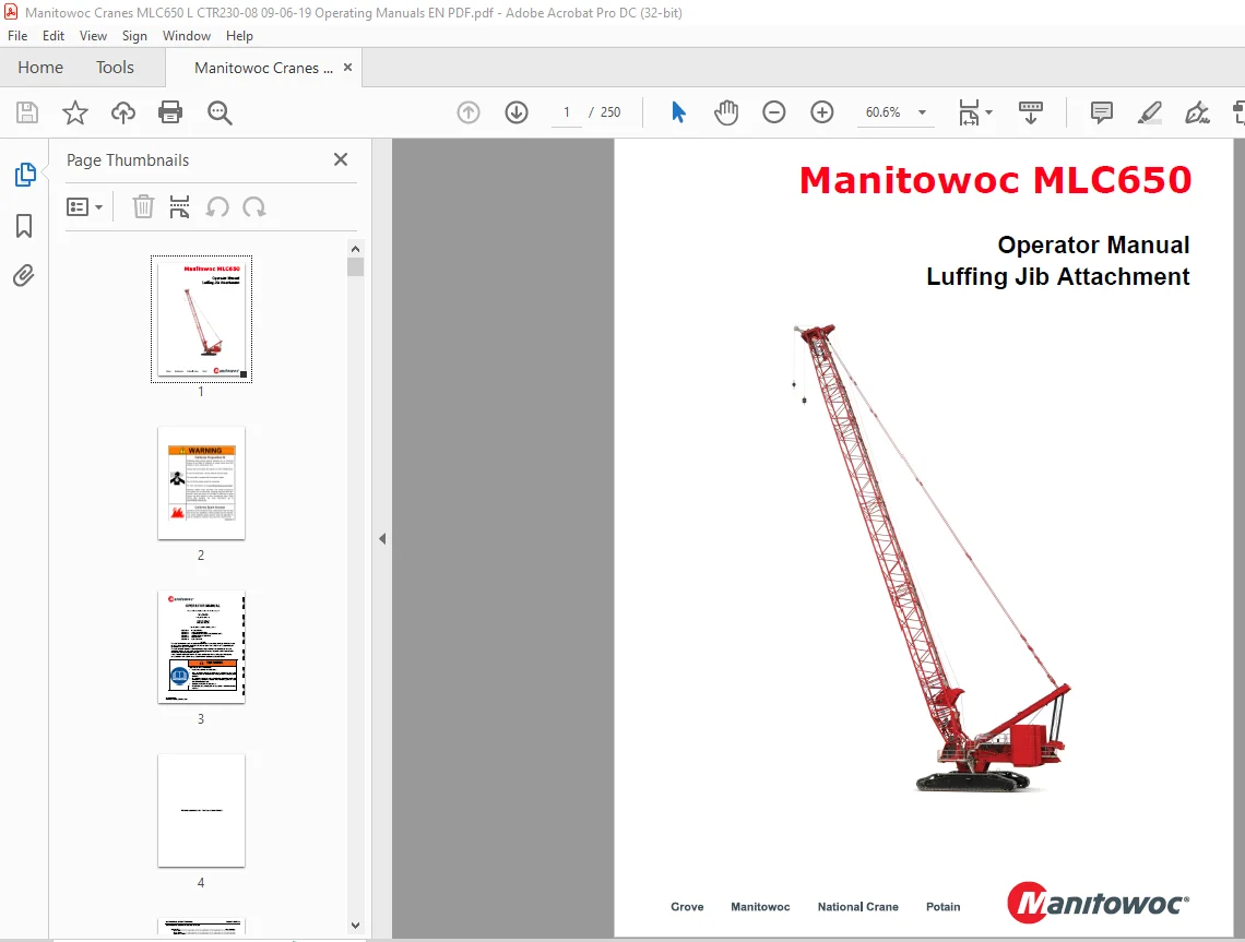
Manitowoc Crane MLC650 Luffing Jib Attachment Operator Manual PDF
$28.95
The Manitowoc Crane MLC650 Luffing Jib Attachment Operator Manual, in PDF format, is a crucial resource for operating the MLC650 crane with luffing jib. Download for comprehensive guidance, featuring operational instructions and essential safety protocols.
Description
Manitowoc Crane MLC650 Luffing Jib Attachment Operator Manual – PDF DOWNLOAD
FILE DETAILS:
Manitowoc Crane MLC650 Luffing Jib Attachment Operator Manual – PDF DOWNLOAD
Language : English
Pages : 250
Downloadable : Yes
File Type : PDF
IMAGES PREVIEW OF THE MANUAL:
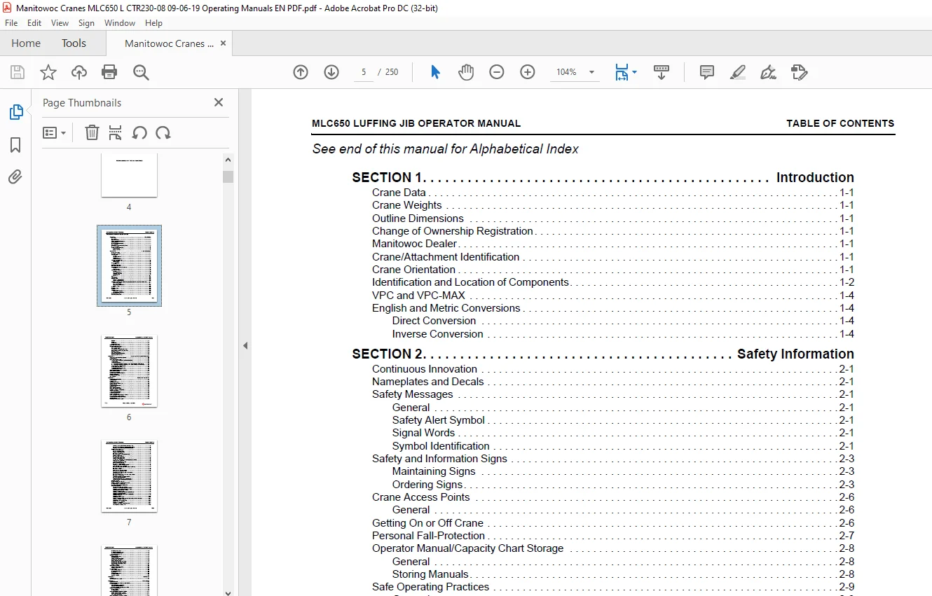
TABLE OF CONTENTS:
Manitowoc Crane MLC650 Luffing Jib Attachment Operator Manual – PDF DOWNLOAD
SECTION 1 11
Introduction 13
Crane Data 13
Crane Weights 13
Outline Dimensions 13
Change of Ownership Registration 13
Manitowoc Dealer 13
Crane/Attachment Identification 13
Crane Orientation 13
Identification and Location of Components 14
VPC and VPC-MAX 16
English and Metric Conversions 16
Direct Conversion 16
Inverse Conversion 16
SECTION 2 19
Safety Information 21
Continuous Innovation 21
Nameplates and Decals 21
Safety Messages 21
General 21
Safety Alert Symbol 21
Signal Words 21
Symbol Identification 21
Safety and Information Signs 23
Maintaining Signs 23
Ordering Signs 23
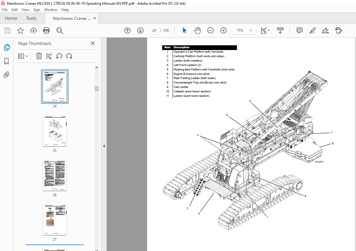
Crane Access Points 26
General 26
Getting On or Off Crane 26
Personal Fall-Protection 27
Operator Manual/Capacity Chart Storage 28
General 28
Storing Manuals 28
Safe Operating Practices 29
General 29
Read Operator Manual 29
Operator Qualifications 29
Operator Conduct 29
Handling Load 31
Signals 34
Safety Devices 35
Operational Aids 35
Category 1 Operational Aids 35
Category 2 Operational Aids 36
Assembling, Disassembling, or Operating Crane Near Electric Power and Transmission Lines 37
Electrocution Hazard 37
Set-Up and Operation 37
Electrocution Hazard Devices 38
Electrical Contact 38
Refueling 39
Fire Extinguishers 39
Accidents 39
Safe Maintenance 39
Maintenance Instructions 39
Safe Maintenance Practices 39
Environmental Protection 41
Boom Disassembly Safety 43
General 43
Location 43
Pin Removal 43
Disassembly Precaution 43
Personnel Handling Policy 44
Pedestal/Barge Mounted Cranes 45
Pedestal Mounted Crane 46
Barge Mounted Crane 46
Capacity Charts for Barge Mounted Crane 47
Shock Loading Caused by Barge Dynamics 47
Operation on Barge 47
Barge Mount Definitions 48
Inspection of Barge-Mounted Crane 48
Transporting Crane on Barge 48
SECTION 3 49
Operating Controls and Procedures 51
Standard Hand Signals for Crane Operation 52
General Operation 54
Luffing Jib Operating Controls 55
1 – Rated Capacity Limiter/Indicator (RCL/ RCI) Display 55
2 – Main Display 55
3 – Limit Bypass Switch 56
4a – Drum 4 (Boom Hoist) Park Switch (Standard – Crane configured with Live Mast) 56
4b – Drum 5 (Boom Hoist) Park Switch (VPC- MAX – Crane configured with Fixed Mast) 56
5 – Drum 6 (Luffing Hoist) Park Switch 56
6 – Wind Speed Transmitter 56
7 – Mechanical Boom Angle Indicator 56
8 – Mechanical Crane Level 56
Operating Limits Identification and Operation 57
Luffing Jib Mode Selection 63
Resetting Luffing Jib Limits 64
Drum and Control Handle Identification 65
Operating Precautions 66
Leaving Crane Unattended 67
Wind Conditions 67
SECTION 4 69
Set-up And Installation 71
General Setup and Installation 71
Crane Orientation 71
Accessing Parts 71
Personal Fall-Protection 72
Crane Weights and Shipping Data 72
Operating Controls 72
Counterweight Requirement 72
Blocked Crawlers 72
Luffing Jib Rigging Drawing 73
Luffing Jib Raising Procedure 73
Identifying Boom and Jib Components 73
Handling Components 75
Shipping Crane Components 77
Assist Crane Requirements 77
Retaining Connecting Pins 77
Manitowoc Supplied Lifting Slings and Shackles 79
Pin and Connecting Hole Cleanliness 79
Connecting/Disconnecting Electric Cables 79
Cable Cleanliness 79
Preparing the Crane For Luffing Jib 81
Removing the Lower Boom Point from the Boom Top 83
Installing the Lower Boom/Jib Point in the Luffing Jib Top 83
Removing the Lower Boom/Jib Point from the Jib Top 83
Installing the Luffing Jib 85
Installing The Jib Strut Butt 85
Installing The Main Strut Butt 87
Erecting the Strut Raising Arm 91
Installing the Jib Strut Top 91
Installing the Frontstay Spreader Assembly 93
Reeving the Strut Tops 95
Installing the Main Strut Top 99
Preparing the Backstay Straps 100
Reeving the Strut Raising Arm 103
Attaching the 12M Straps to the Frontstay Spreader Assembly 105
Raising the Strut Assemblies 106
Assembling the Jib Butt Assembly 109
Lifting the Jib Butt Assembly 111
Installing the Jib Butt Assembly 113
Removing the 12M Insert Roller Assembly 113
Using the Luffing Jib as a Hold Back 115
Installing the Main Strut Stops and Frontstay Strap Hookup 117
Installing the Jib Inserts 119
Installing the Jib Top 119
Raising the Jib Top Wire Rope Guide 121
Installing the Lower Boom/Jib Point 121
Connecting the Jib Straps between the Jib Sections 123
Installing the Load Links 125
Installing the Position Light and the Wind Speed Indicator 126
Installing the Jib Top Camera 129
Connecting the Luffing Jib Electrical Cables 131
Installing the Upper Boom Point 133
Routing the Load Lines to the End of the Luffing Jib 135
Preparing the Intermediate Suspension Pendants 137
Pre-Raising Checks 138
Raising The Boom and Luffing Jib 139
Installing the Boom Block Up Limit Components 145
Lowering the Boom and Luffing Jib 147
Removing the Block Up Limit Components 155
Luffing Jib Disassembly 156
Resetting the Jib Stop Raising Roller 156
Removing the Intermediate Suspension Pendants 159
Removing the Load Lines from the End of the Jib 159
Disconnecting the Jib Electrical Cables 161
Removing the Jib Top Camera 162
Removing the Position Light and Wind Speed Indicator 163
Removing the Upper Boom Point 165
Disconnecting the Jib Straps between the Jib Sections 167
Removing the Load Links 169
Removing the Jib Top 171
Disassembling the Jib Inserts 171
Reeving the Main Strut Raising Arm and Disconnecting the Main Strut Stops 173
Removing the Jib Butt Assembly 175
Disassembling the Jib Butt Assembly 177
Lowering the Strut Assemblies 178
Removing the 12M Straps 179
Removing the Frontstay Spreader Assembly 181
Unreeving the Strut Raising Arm 183
Unreeving the Strut Tops 185
Lowering the Strut Raising Arm 187
Removing the Main Strut Butt 189
Removing the Jib Strut Butt 193
Wire Rope Installation 195
Wire Rope Specifications 195
Wire Rope Storage 195
Seizing and Cutting Wire Rope 195
Anchoring Wire Rope to Drum 196
Winding Rope onto Drum 196
Anchoring Wire Rope to Wedge Socket 199
Anchoring Wire Rope to Button Socket 199
Pad Eye Usage for Wire Rope Reeving 201
Breaking in Wire Rope 201
Rigging Winch Operation 202
Selecting Rigging Winch Mode 202
Operating Rigging Winch 203
Load Line Reeving 204
Guide Sheaves and Drums 204
Load Block Identification 204
Duplex Hook 204
Wire Rope Specifications 204
Load Block Reeving 204
Dead End Locations 205
SECTION 5 207
Lubrication 209
Lubrication 209
Lube and Coolant Product Guide 209
SECTION 6 211
Maintenance 213
General Maintenance 213
Calibrating the Boom and Luffing Jib Angle Indicators 213
Automatic Boom Stop 215
Automatic Boom Stop Maintenance 215
Adjusting Automatic Boom Stop 217
Replacing Automatic Boom Stop Actuator Rod 217
Physical Jib Stop Operation 221
Raising Operation 221
Lowering Operation 221
Luffing Jib Stop Position Switches — Version 1 223
Jib Stop Position Switches Adjustment 223
Jib Stop Position Switches Maintenance 223
Actuator Rod Replacement 223
Luffing Jib Stop Position Switches — Version 2 225
Jib Stop Position Switches Adjustment 225
Jib Stop Position Switches Maintenance 225
Automatic Luffing Jib Stop – MAX UP 227
Jib Stop Max Up Maintenance 227
Jib Stop Max Up Pre-Erection Checks 227
Jib Stop Max Up Actuator Rod Adjustment 227
Jib Stop Max Up Operational Check 227
Replacing Jib Max Up Actuator Rod 229
Automatic Luffing Jib Stop – MAX DOWN 231
Jib Stop Max Down Maintenance 231
Jib Stop Max Down Pre-Erection Checks 231
Jib Stop Max Down Actuator Rod Adjustment 231
Jib Stop Max Down Operational Check 231
Replacing Jib Stop Max Down Actuator Rod 233
Drum 6 Pawl Limit Switch 235
Operation 235
Adjustment 235
Maintenance 235
Sheave Proximity Sensor 237
Operation 237
Maintenance 237
Adjustment 237
Drum 6 Oil Change 239
General 239
Maintenance 239
Installing and Adjusting the Block- Up Limit 241
General 241
Removing the Luffing Jib 241
Block-Up Limit Switch Maintenance 243
Adjusting the Block-up Limit Switch 243
Jib Stop Accumulator Maintenance 245
Operation 245
Maintenance 245
Customer Support: [email protected]
S.M