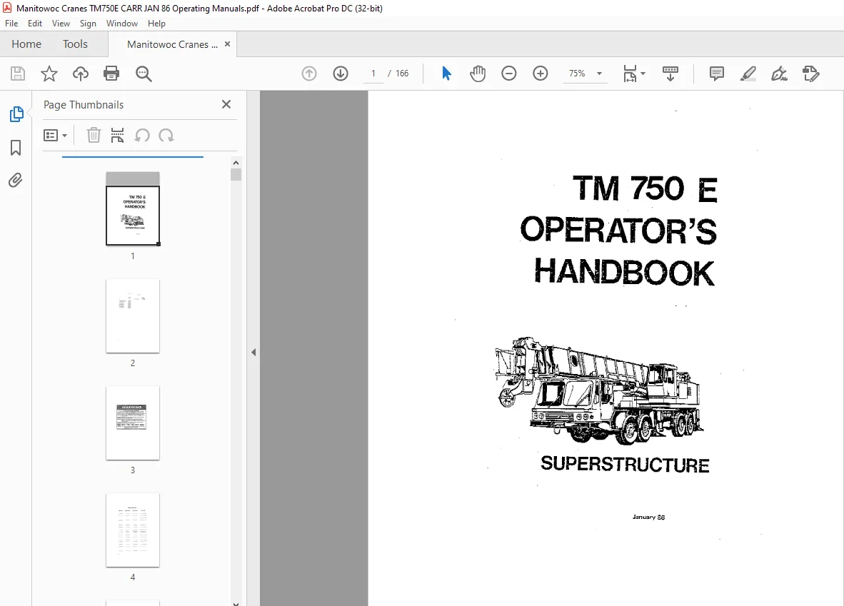
Manitowoc Crane TM 750E Superstructure Operator’s Handbook Manual PDF
$27.95
Description
Manitowoc Crane TM 750E Superstructure Operator’s Handbook Manual – PDF DOWNLOAD
The Manitowoc Crane TM 750E Superstructure Operator’s Handbook Manual in PDF is essential for safe operation. Download for detailed instructions and reference.
FILE DETAILS:
Manitowoc Crane TM 750E Superstructure Operator’s Handbook Manual – PDF DOWNLOAD
Language : English
Pages : 166
Downloadable : Yes
File Type : PDF
IMAGES PREVIEW OF THE MANUAL:
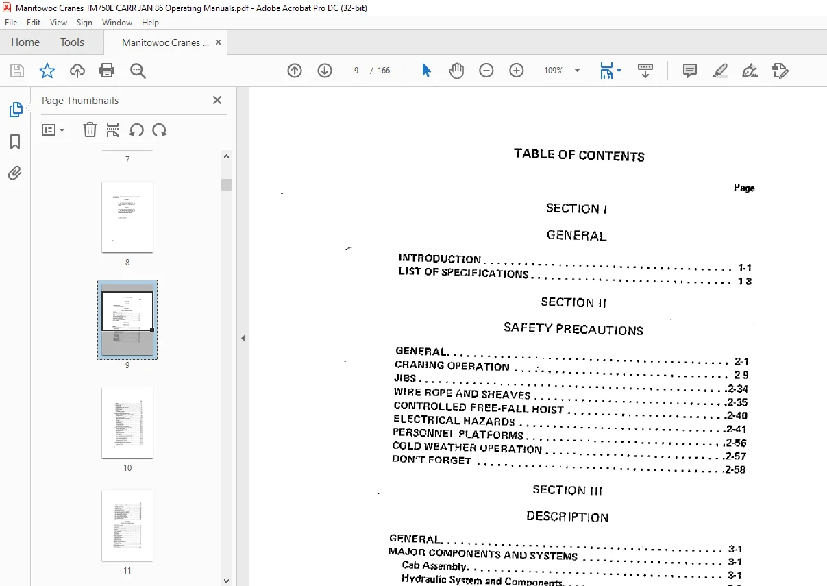
TABLE OF CONTENTS:
Manitowoc Crane TM 750E Superstructure Operator’s Handbook Manual – PDF DOWNLOAD
SECTION I
GENERAL
Page
INTRODUCTION 1-1
LIST OF SPECIFICATIONS _ 1″3
SECTION 11
SAFETY PRECAUTIONS
GENERAL 2-1
CRANING OPERATION :·- 2-9
JIBS f 11 2-34
WIRE ROPE AND SHE;AVE:S 2-35
CONTROLLED FREE-FALL HOIST 2-40
ELECTRICAL HAZARDS 2 41
PERSONNE;L PLATFORMS 2-56
COLD WEATHER OPERATION 2-57
OON’T FORGET 2-58
SECTION Ill
DESCRIPTION
GE;NERAL 3-1
MAJOR COMPONENTS AND SYSTEMS 3-1
Cab Assembly 3-1
Hydraulic System and Components 3-2
Reservoir 3-2
Direc’l;ional Control Valves _ 3-2
Hydraulic Boost Circuit 3-2
Turnt ible Assembly and Swing Mechanism 3–2
Swing Brake _ 3-3
Swing Motor 3-3
Swing Gearbox _ 3-3
Boom Assembly 3-3
Main Hoist _ 3-3
Outrigger Sy~tern 3-3
Counterweight _ · 3-4
ix
Page
Swivels 3-4
OPTIONAL EQUIPMENT 3-4
Revolving Light 3-4
Auxiliary Hoist _ · 3–5
Outrigger Stabilizer Spin-Type Locks 3-5
Swingaway Extension J- 5
Boom Floodlights 3-5
Spotlight 3-5
Electrical Skylight Wiper 3·9
Boom Elevation Indicator 3-9
ENGINE CONTROLS AND INDICATORS 3-9
High Water Temperature/Low Oil Pressure Indicator
(C1 1111rnins Engine) 3-9
Water Temperature Gauge (Cummins Engine! 3-9
Engine Oil Pressure Gauge 3-9
Engine Distress Indicator (Deutz Engine) 3-10
Tachometer 3-1 0
Voltmeter · 3-10
Fuel Quantity Gauge 3·10
Ignition Switch – 3-11
Ignition On Indicator : 3-11
Throttle Lock Control J- 11
Foot Throttle Pedal 3-11
Engine Quick Start Sy~tem (Optional) 3-12
ACCESSORY CONTROLS AND INDICATORS · 3-12
Instrument Lights Switch 3·1:2
Windshield Wiper/Washer Switch 3-12
Cab Circulation Fan 3·12
Domelight ~ _ 3-12
Panel Light and Switch 3·12
Fire Extinguisher · 3-13
Defroster Control (Cummins Engine) _ 3·13
Heater Temperature Control (Cummin5 Engine) _ 3-13
Heater Fan Switch (Cummins: Engine! _ 3-13
Beacon Light Switch (Optional) 3-13
Boom Light Switch (Optional) 3-13
Spotlight and Switch (Optional) 3-13
Manual Skylight Wiper 3 13
Eim::tric Skylight Wiper (Optionall _ 3·14
CRANING CONTROLS AND INDICATORS _ _ 3·14
Swing Horn Button 3-14
Swing Control Lever and Pedal 3-14
X
Page
Front Stabili:z:er Overload Indicator 3″14
Bubble Lever Indicator 3-14
Outrigger Control Panel 3-14
Swing Brake Pedal 3-15
Swil”lg Brake Control Valve 3-15
Main Hoist Control Lever 3-15
Auxiliary Horst Control Lever (Optional) 3·15
Boom Elevation Control Lever and Pedal 3-15
Inner-Mid Tele5cOpe Control Lever 3-16
Outer-Mid Telescope Control Lever 3-16
Boom Latch Pin Control Switch 3-16
Boom Latch Pin Engaged Indicator 3-16
Hoist Rotation Indicators (Optional) _ 3-16
Lock Pin Control Handle _ 3·16
Main Hoist Speed Selector Switch 3-17
SECTION IV
OPERATING PROCEDURES
PRESTARTING CHECKS 4-1
Fuel Supply 4-1
Engine Oil : 4-1
Engine Coolant {Cummins Only) 4-1
Batteries 4-1
Hydraulic Oil Reservoir and Filter 4-1
Daily Lubrication- : 4-1
Wire Rope 4-2
Hook Blocl-s 4-2
Air Cle: mer _ 4-2
ENGINE OPERATION 4-2
Starting Procedure 4-~
Cold Weather Starting 4-4
Idling the Engine 4-4
Racing the Engine _ · 4-5
Shutdown Procedure 4-5
GENERAL CRANE OPERATION 4-5
Handling the Loo1d _ _ 4-5
Control Lever Operation 4-7
Preload Check_ 4-7
USING YOUR LOAD CHART 4-8
CRANE FUNCTIONS -=- · 4-10
xi
Page
Setti11g the Outriggers 4-11
Stowing the Outriggers 4-12
Setting the Center Front Stabilizer 4-14
Stowing the Center Front StabiUzer 4-15
Swinging the Boorn 4-16
Elevating and Lowering the Boom 4-17
Elevating the Boom 4· 17
Lowering the Boom 4-17
Foot Control ‘ 4-18
Emergency Boom Operating Procedures 4-18
Telescoping the Boom 4-19
Extending the 8oom 4-19
Retr icting the Boom 4-19
POWER-PINNED FLY SECTION 4-20
Extending the Power Pinned Fly 4-20
Retracting the Power Pinned Fly 4-21
Lowering and Rai5ing the Cable 4-22
Lowering the Cable _ 4·23
Raising the Cable 4-23
OPTIONAL EQUIPMENT OPERATION 4-23
HOT WATER HEATER (CUMMINS ENGINE) 4-23
Operating _ 4-23
DIESEL FUEL HEATER (DEUTZ ENGINE) 4-23
Starting 4-23
Stopping 4-23
SECTION V
OPERATIONAL AIDS
GENERAL 5-1
KRUEGER LOAD MOMENT INDICATING (LMll SYSTEM 5·1
KRUEGER ANTITWO-BLOCK (HI SYSTEM 5-1
KRUEGER HAP AND HLAP SYSTEMS 5-1
CONTROL LEVER LOCKOUT SYSTEM 5-2
SECTION VI
LUBRICATION
GENERAL _ 6-1
LUBRICANTS 6-1
xii
Page
Hydraulic Oil Recommendations 6-4
Viscosity 6-6
Arctic Conditions (Below O Degrees F (-18 Degrees C] I 6- 6
Antivvear Additives – 6–6
LUBRICATION POINTS 6-6
WIRE ROPE LUBRICATION : 6-22
SECTION VII
SET UP AND INSTALLATION PROCEDURES
GE;Nl:cRAL _ 7-1
INSTALLING CABLE ON THE HOIST DRUM 7-1
CABLE REEVING 7-2
ERECTING AND STOWING HIE 35 FOOT (10 7 M)
SWINGAWAY EXTENSION _ ~ 7-3
Erecting 7-3
Stowing 7-11
Setting the Tl!lleseoping Exter sion Length 7-13
Extending 7-13
Stowing 7·14
Setting the Offset _ 7-15
15 or 30 degrees _ 7-15
Minimum Offset (3 degrees) 7·16
Questions? Email us: [email protected]
S.V