Manitowoc Cranes M 1200 F1542 02-02-1996 Operating Manual PDF
$12.95
Manitowoc Cranes M 1200 F1542 02-02-1996 Operating Manual – PDF DOWNLOAD
Description
Manitowoc Cranes M 1200 F1542 02-02-1996 Operating Manual – PDF DOWNLOAD
FILE DETAILS:
Manitowoc Cranes M 1200 F1542 02-02-1996 Operating Manual – PDF DOWNLOAD
Language : English
Pages : 18
Downloadable : Yes
File Type : PDF
IMAGES PREVIEW OF THE MANUAL:
TABLE OF CONTENTS:
Manitowoc Cranes M 1200 F1542 02-02-1996 Operating Manual – PDF DOWNLOAD
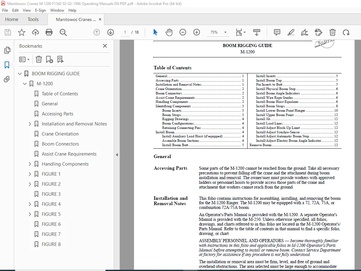
BOOM RIGGING GUIDE 1
M-1200 1
Table of Contents 1
General 1
Accessing Parts 1
Installation and Removal Notes 1
WARNING 2
Read Capacity Charts! 2
Crane Orientation 2
Boom Connectors 2
Assist Crane Requirements 2
Handling Components 2
CAUTION 2
Boom Section Damage! 2
FIGURE 1 3
Identifying Components 3
Boom Inserts 3
Boom Straps 3
Rigging Drawings 4
Boom Configurations 4
Retaining Connecting Pins 4
Install Boom 4
DANGER 4
Collapsing Boom Hazard! 4
Install Auxiliary Load Hoist (if equipped) 4
Assemble Boom Sections 4
Install Boom Butt 5
1 Lift boom butt into position at front roller carrier and align connecting holes Use inboard lugs for 75A boom; use outboard lugs for 72, 72A, or 72/75A boom (Figure 2, View A) 5
2 Install hinge pins and keeper plates as shown in Figure 2, View A 5
3 Lower boom butt onto blocking Boom centerline does not have to be parallel to ground at this time Six-inch (15 cm) blocking may be used if desired See Figure 2, View B 5
Install Inserts 5
1 Lift boom insert adjacent to boom butt into place (Figure 2, View C) Engage top FACT™ connectors only Block insert at each end (Figure 2, View D) 5
2 Lift remaining inserts into place in proper sequence and pin securely Block upper end of each insert as assembly progresses (Figure 2, View E) 5
Install Boom Top 5
1 Lift boom top into place into position and pin to adjacent boom insert 5
2 Block under end of boom top 5
Pin Inserts to Butt 5
1 Attach nylon lifting slings to chords at top end of boom butt and bottom end of adjacent boom insert (Figure 2, View F) 5
2 Hook assist crane to slings Crane must have capacity to lift 1/2 the weight of assembled boom 5
3 Lift butt and boom until bottom pin holes are aligned (Figure 2, View G) 5
4 Insert bottom pins to connect boom insert to boom butt (Figure 2, View H) 5
Install Physical Boom Stop 6
1 For 75A boom, pin boom stop frame to boom butt (Figure 3, View A) 6
2 Pin slotted end of boom stop arm to each boom stop tube (Figure 3, View A or B) A flat washer is required on both ends of pins 6
3 Lift boom stop tube into position with assist crane Pin tube to lug on transverse adapter beam 6
4 Pin end of boom stop arm to lug on boom butt (Figure 3, View B or C) 6
5 Repeat steps for other boom stop tube 6
6 Connect air lines from crane to quick couplers on boom stop tubes 6
7 Start crane engine and pressurize air system to extend air cylinders in boom stop tubes 6
Install Boom Angle Indicators 6
1 Securely fasten mechanical boom angle indicator to inboard side of right boom butt leg (Figure 3, View C) 6
2 Securely fasten junction box for electric boom angle indicator to inboard side of right boom butt leg (Figure 3, View C) 6
Install Wire Rope Guides 6
1 Lift wire rope guide into position and bolt to boom butt (Figure 3, View D or View E) 6
2 Pin wire rope guides to bottom of boom inserts at locations shown on Boom Rigging Assembly drawing (if equipped with optional upper boom point) 6
Install Boom Hoist Equalizer 6
1 Lift equalizer frame (72 or 72A boom) or rails (75A boom) into position and pin to insert or boom top (Figure 3, View F or G) Refer to Boom Rigging Assembly drawing for location 6
2 Lift equalizer into position and pin to frame or rails (Figure 3, View F or G) 6
3 Pin appropriate links to equalizer 6
FIGURE 2 7
Install Boom Straps 8
1 Pin boom strap supports (Figure 4, View A) to appropriate inserts Refer to Boom Rigging Assembly drawing for locations 8
2 Lift basic straps into position and pin to boom top 8
3 Pin remaining straps in proper sequence to basic straps using connecting links (Figure 4, View B) 8
4 Lay straps in supports as assembly progresses Then go to step 6 8
5 If boom sections were shipped with boom straps in shipping position (Figure 4, View C), proceed as follows: 8
a Remove shipping pins (Figure 4, View C) and store in holes provided (Figure 4, View A) 8
b Rotate links to operating position (Figure 4, View A) 8
c Pin links to straps (Figure 4, View B) 8
6 Pin last set of straps to links on equalizer 8
7 Unpin equalizer from frame or rails 8
CAUTION 8
Equipment Damage! 8
FIGURE 3 9
FIGURE 4 10
Install Lower Boom Point Hanger 10
1 Remove pins connecting boom hoist equalizer to frame or rails (Figure 3, View F or G) 10
2 Mark on ground location of hanger pin holes in boom top 10
3 Boom up so that boom is approximately 10 ft (3 m) above ground Swing boom to side to allow room for placement of boom point hanger 10
4 Hook assist crane to lifting lugs on boom point hanger (Figure 5) Place hanger on ground at position previously marked 10
5 Swing boom back over boom point hanger 10
6 Using assist crane, lift boom point hanger into position under boom top or insert 10
7 Unpin links from stored position on boom top or insert 10
8 Pin links to end of boom point hanger (Figure 5, View B or C) Leave hanger in stored position until load lines are installed 10
FIGURE 5 11
Install Upper Boom Point 12
Install Jib 12
Install Load Lines 12
1 Place load block approximately 6 ft (1 8 m) to rear and side of lower boom point hanger Anchor load block securely so it cannot move 12
2 Route load lines through guide sheaves Install rope guards and pins to retain wire rope on guide sheaves 12
3 Reeve load block and lower boom point hanger according to reeving diagrams in Operator/Parts Manual 12
Install/Adjust Block-Up Limit 12
Install/Adjust Synchro-Sensor 12
Install/Adjust Automatic Boom Stop 12
Install/Adjust Electric Boom Angle Indicator 12
Remove Boom 12
CAUTION 12
Jib Damage! 12
1 Lower boom onto blocking at ground level Fold lower boom point hanger under boom as boom is lowered 12
2 Place load block approximately 6 ft (1 8 m) away from lower boom point hanger Anchor load block securely so it cannot move 12
3 Remove or disconnect the following as appropriate (refer to folios in Operator/Parts Manual for instructions): 12
4 Using assist crane, lift lower boom point hanger into stored position Pin links to bottom end of hanger (Figure 5, View B or C) 13
5 Remove rope guards and pins on guide sheaves Remove load lines and store 13
6 Remove jib, if installed Refer to Jib Rigging folio for instructions 13
7 Remove upper boom point, if installed 13
8 Hook assist crane to lifting lugs on lower boom point hanger (Figure 5) Unpin lower boom point hanger from boom top or insert and lower to ground Unhook assist crane 13
9 Boom up so boom is above lower boom point hanger, swing boom to side, and remove lower boom point hanger 13
10 Boom down so that boom hoist equalizer rests on frame or rails Insert pins to connect equalizer to frame or rails (Figure 3, View F or G) 13
11 Unpin straps from links on boom hoist equalizer (Figure 3, View F or G) 13
12 If required, disassemble and remove links from between boom straps (Figure 4, View A) Then remove all boom straps and supports 13
13 If boom straps and links are to be shipped on the boom sections: 13
a Unpin one end of links from straps 13
b Rotate links to stored position (Figure 4, View C) 13
c Pin links and straps to supports with shipping pins (Figure 4, View C) 13
14 Remove boom hoist equalizer from frame or rails 13
15 Remove wire rope guide if boom butt if required by shipping restrictions 13
16 Disconnect air lines from crane at quick couplers on boom stop tubes (tubes will retract) Then remove physical boom stops 13
DANGER 13
Collapsing Boom Hazard! 13
17 Unpin boom from butt: 14
a Attach nylon lifting slings to chords at top end of boom butt and bottom end of adjacent boom insert (Figure 3, View G) 14
b Hook assist crane to slings Crane must have capacity to lift 1/2 the weight of assembled boom 14
c Remove bottom pins connecting boom insert to boom butt (Figure 2, View H) If necessary, lift boom slightly to relieve pressure on pins 14
d Lower boom butt and boom sections onto blocking (Figure 2, View F) 14
18 Remove boom top 14
19 Remove boom inserts 14
20 Remove boom butt 14
FIGURE 6 15
FIGURE 7 16
FIGURE 8 17
S.V 06/24