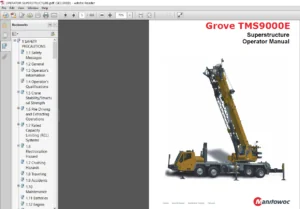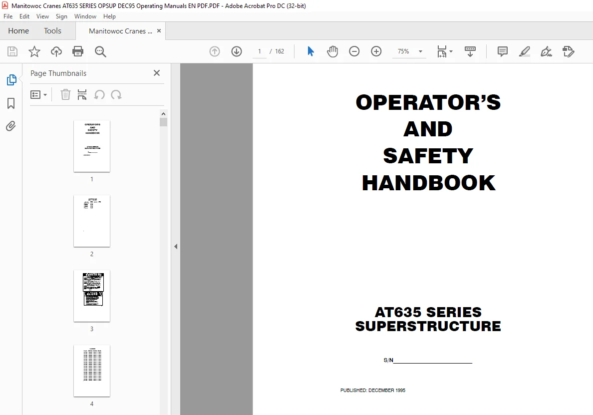
Manitowoc Grove Crane AT635 SERIES SUPERSTRUCTURE Operator Manual PDF
$27.95
Description
Manitowoc Grove Crane AT635 SERIES SUPERSTRUCTURE Operator Manual – PDF DOWNLOAD
FILE DETAILS:
Manitowoc Grove Crane AT635 SERIES SUPERSTRUCTURE Operator Manual – PDF DOWNLOAD
Language : English
Pages : 162
Downloadable : Yes
File Type : PDF
IMAGES PREVIEW OF THE MANUAL:
TABLE OF CONTENTS:
Manitowoc Grove Crane AT635 SERIES SUPERSTRUCTURE Operator Manual – PDF DOWNLOAD
SECTION I
GENERAL
INTRODUCTION 1−1
SECTION II
SAFETY PRECAUTIONS
GENERAL 2−1
CRANING OPERATION 2−7
JIBS 2−24
WIRE ROPE AND SHEAVES 2−25
CONTROLLED FREE−FALL HOIST 2−30
ELECTRICAL HAZARDS 2−30
PERSONNEL PLATFORMS 2−42
COLD WEATHER OPERATION 2−42
DON,T FORGET 2−43
OPERATING PRECAUTIONS 2−44
HYDRAULIC SYSTEM 2−49
SECTION III
CAB CONTROLS AND INDICATORS
GENERAL 3−1
Engine Controls and Indicators 3−1
Battery Circuit Switch 3−1
Alternator Warning Light (Red) 3−1
Low Oil Pressure Warning Light 3−2
High Engine Temprtature Warning Light 3−2
Fuel Quantity Gauge 3−2
Tachometer 3−2
Foot Throttle Pedal 3−2
Hand Throttle 3−2
Site Crane Controls and Indicators 3−2
Swing and Telescope or Auxiliary Hoist Control Lever 3−2
Boom Lift and Main Hoist Control Lever 3−3
Hoist Rotation Indicators − Optional 3−3
Telescope Control Pedal − Optional 3−3
xi
Page
Swing Park Brake Switch 3−4
Swing Brake Pedal 3−4
Swing Lock Control 3−4
Level Indicator 3−4
Hoist Boost 3−4
Hoist Over Lower Override Switch 3−4
Warning Horn 3−5
Axle Suspension Lock Switch (Spring Suspenion Only) 3−5
Axle Suspension Lock Warning Light (Spring Suspenion Only) 3−5
Suspension Locked Warning Light (Yellow) 3−5
Differential Lock Switch 3−5
Auxiliary Hoist Selector Switch (Optional) 3−6
Warning Light (Green) 3−6
Dual Air Pressure Gauge 3−6
Low Air Pressure Indicator Warning Light (Red) 3−6
Park Brake Control 3−6
Park Brake Indicator Warning Light (Red) 3−6
Brake Foot Pedal 3−6
Rear Steering Warning Light (Red) 3−7
P T O Warning Light (Green) 3−7
Rear Steer Control (Orbitrol Steering) 3−7
Steer Control Switches (Electrical Tiller Steering) 3−7
Rear Steer Indication Gauge 3−7
Outrigger Selector Panel 3−7
Safe Load Indicator Panel 3−7
Gearshift 3−8
Accessory Controls and Indicators 3−8
Panel Light Dimmer Control 3−8
Roof Wiper Switch 3−8
Heater Switch (Optional) 3−9
Heater Control Panel (Optional) 3−9
Windscreen Wiper/Washer Switch 3−9
Cigar Lighter 3−10
Test Switch 3−10
Lights Switch (Optional) 3−10
Rotating Beacon Switch (Optional) 3−10
Armrest Lever 3−10
Fire Extinguisher 3−10
Heat Control (Optional) 3−10
Duty Selector Switch (Optional) 3−10
xii
Page
SECTION IV
OPERATING PROCEDURES
PRE−STARTING CHECKS 4−1
Fuel Supply 4−1
Engine Oil 4−1
Engine Coolant 4−1
Batteries 4−1
Signal and Running Lights 4−1
Foot and Parking Brakes 4−2
Daily Lubrication 4−2
Hydraulic Reservoir 4−2
Steering Mode 4−2
Tyres 4−3
Wire Rope 4−3
Hookblock 4−3
Air Cleaner 4−3
ENGINE OPERATION 4−3
Starting Procedure 4−3
Cold Weather Starting 4−5
Idling the Engine 4−5
Racing the Engine 4−5
Shutdown Procedure 4−6
CRANE OPERATION 4−6
CRANE TRAVEL OPERATION 4−7
Travelling General 4−7
Moving the Crane 4−8
Superstructure Travel − Pick and Carry Duties 4−9
Steering 4−9
Travelling Forward 4−12
Travelling Reverse 4−13
Control Lever Operation 4−13
Preload Check 4−13
USING YOUR LOAD CHART 4−14
CRANE FUNCTIONS 4−15
Setting the Outriggers 4−15
To Extend the Outriggers 4−18
To Retract the Outriggers 4−20
Remote Control Outriggers 4−20
To Extend the Outriggers 4−21
To Retract the Outriggers 4−22
Level Indicator 4−23
Operating Stabilizers Only 4−23
xiii
Page
Partial Outreach Extension − Optional 4−24
Swinging the Boom 4−26
Elevating and Lowering the Boom 4−27
Elevating the Boom 4−27
Lowering the Boom 4−27
Telescoping the Boom 4−28
Extending the Boom 4−28
Retracting the Boom 4−29
Lowering and Raising the Cable 4−29
Lowering the Cable 4−29
Raising the Cable 4−30
Emergency Boom Operating Procedures 4−30
Stowing and Parking 4−31
SECTION V
LUBRICATION
GENERAL 5−1
LUBRICANTS 5−1
Hydraulic Oil Recommendations 5−5
Viscosity 5−5
Arctic Conditions (Below 0 degrees F [−18 degrees C]) 5−6
Anti wear Additives 5−7
LUBRICATION POINTS 5−7
VAPOUR CORROSION INHIBITOR 5−16
WIRE ROPE LUBRICATION 5−17
SECTION VI
OPERATIONAL AIDS
GENERAL 6−1
LOAD MOMENT INDICATING SYSTEM 6−1
SECTION VII
SET UP AND INSTALLATION PROCEDURES
GENERAL 7−1
INSTALLING CABLE ON THE HOIST 7−1
CABLE REEVING 7−2
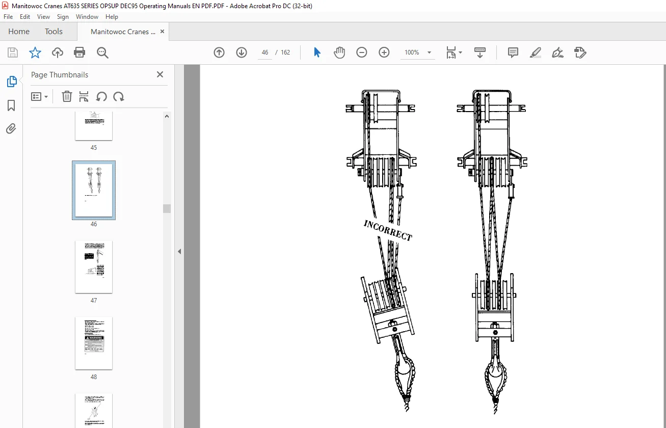
WEDGE AND SOCKET 7−3
Inspection 7−3
Correct Method of Fixing the Rope to the Socket 7−3
Single Hook and Pearweight 7−6
ERECTING AND STOWING THE SWINGAWAY BOOM EXT 7−7
Erecting 7−7
Stowing 7−10
Setting the Offset 7−13
Setting the Telescoping Extension Length 7−14
Extending 7−14
Retracting 7−15
LIST OF FIGURES
Slinging Points 1−3
Cab Controls and Indicators (Sheet 1 of 4) 3−11
Cab Controls and Indicators (Sheet 2 of 4) 3−12
Cab Controls and Indicators (Sheet 3 of 4) 3−13
Cab Controls and Indicators (Sheet 4 of 4) 3−14
Terms to Know 4−15
Wire Rope Lubrication 5−17
Lubrication Diagram (Sheet 1 of 5) 5−18
Lubrication Diagram (Sheet 2 of 5) 5−19
Lubrication Diagram (Sheet 3 of 5) 5−20
Lubrication Diagram (Sheet 4 of 5) 5−21
Lubrication Diagram (Sheet 5 of 5) 5−22
Installing Cable Anchor Wedge 7−2
Erecting and Stowing the Swingaway Boom Extension 7−12
Swingaway Offset Positions 7−17
Questions? Email us: [email protected]
S.V