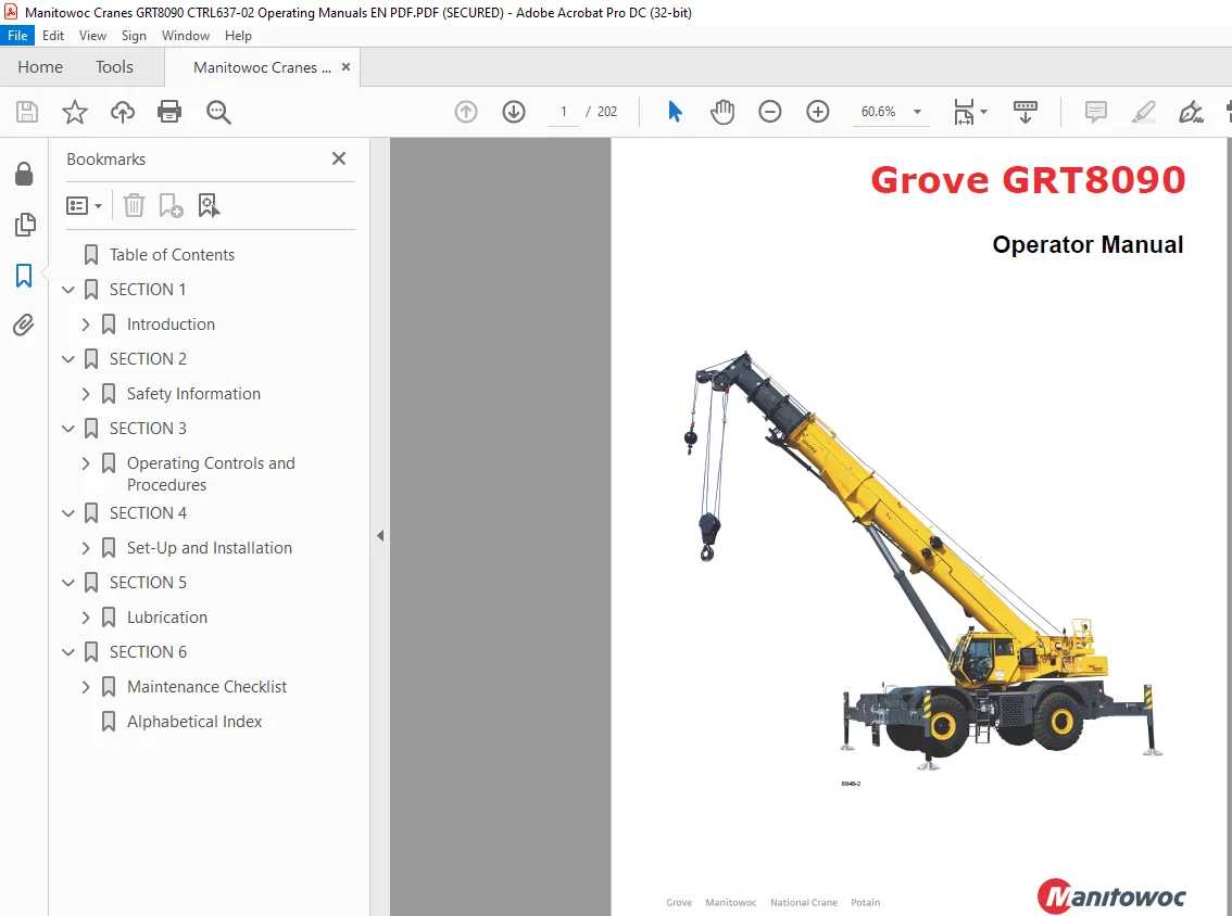
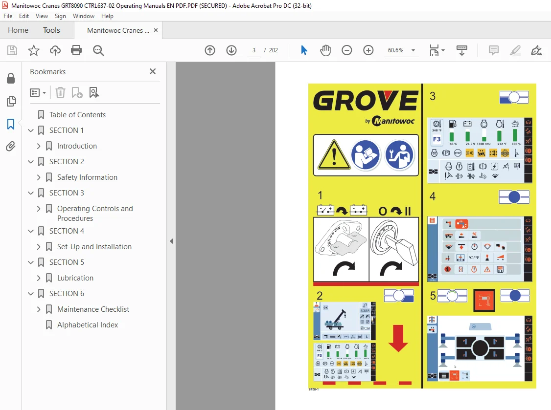
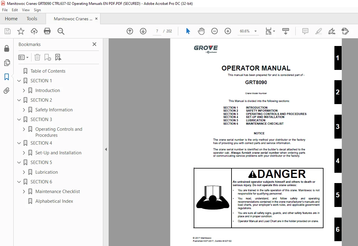
Manitowoc Grove GRT8090 Crane Operation Manual PDF Download
$28.95
The Manitowoc Grove Crane GRT8090 Operator Manual is a crucial guide, providing detailed instructions for safe and efficient operation of the GRT8090 model. Conveniently available as a downloadable PDF for user reference.
Description
Manitowoc Grove Crane GRT8090 Operator Manual – PDF DOWNLOAD
FILE DETAILS:
Manitowoc Grove Crane GRT8090 Operator Manual – PDF DOWNLOAD
Language : English
Pages :202
Downloadable : Yes
File Type : PDF
IMAGES PREVIEW OF THE MANUAL:
TABLE OF CONTENTS:
Manitowoc Grove Crane GRT8090 Operator Manual – PDF DOWNLOAD
Table of Contents 9
SECTION 1 15
Introduction 15
General 15
Customer Support 15
New Owners 15
Noise/vibration Test results 15
Noise Level Test Results 15
Vibration Level Test Results 16
Serial Number Location 16
List Of Specifications 18
General 18
Dimensions 18
Capacities 18
Torque Converter 18
Transmission 18
Engine 18
Cummins QSB 6 7 – Tier 4F 18
Cummins QSB 6 7 – Tier 3 18
Axles 18
Brakes 18
Wheels and Tires 18
Swing Gearbox 18
Boom 18
Swivel Assembly 18
Hydraulic Pumps 19
Pump #1 19
Pump #2 19
Pump #3 19
Hoists 19
SECTION 2 21
Safety Information 21
Safety Messages 21
General 21
Safety Alert Symbol 22
Signal Words 22
General 22
Warning Signs 22
Accidents 22
Operator Information 23
Operator Qualifications 23
Operational Aids 24
Rated Capacity Limiter (RCL) Systems (If Equipped) 24
Anti-Two-Blocking Device 25
Working Area Limiter (If Equipped) 25
Crane Stability/Structural Strength 26
Load Charts 26
Work Site 26
Wind Forces 27
Wind Speeds 27
Determination of 3-second wind gust speed at boom tip height: 30
Size and Shape of the load: 30
Determining Wind Drag Coefficient (Cd) 31
Maximum Permissible Wind Speed 32
Example and Sample Calculations (metric) 34
Example 1: Crane Configuration: 34
Load example 1 1: 35
Load example 1 2: 35
Load example 1 3a: 35
Load example 1 3b: 35
Example and Sample Calculations (Non-metric) 38
Example 2: 38
Load example 2 1: 39
Load example 2 2: 39
Load example 2 3a: 39
Load example 2 3b: 39
Lifting Operations 40
Counterweight 41
Outrigger Lift Off 41
Multiple Crane Lifts 41
Tilt-Up Panel Lifting 41
Pile Driving and Extracting 42
Crane Equipment 42
Crane Inspection 42
Electrocution Hazard 43
Set-Up and Operation 44
Electrocution Hazard Devices 44
Electrical Contact 45
Special Operating Conditions and Equipment 45
Earthing the Crane 45
Personnel Handling 46
Environmental Protection 47
Maintenance 47
Service and Repairs 47
Lubrication 48
Tires 49
Hoist Rope 49
Synthetic Hoist Rope 49
Wire Rope 49
Sheaves 50
Batteries 51
Super Capacitor (If Equipped) 51
General Maintenance 51
Transporting the Crane 52
Travel Operation 52
Work Practices 53
Personal Considerations 53
Crane Access 53
Job Preparation 53
Working 54
Lifting 55
Hand Signals 56
Jib 58
Parking and Securing 58
Shut-Down 58
Cold Weather Operation 58
Temperature Effects on Hook Blocks 59
Temperature Effects on Hydraulic Cylinders 59
Model Specific Information 60
Crane Stability 60
Hoist Platform 61
Travel Position 61
Overload Inspection 61
Boom Inspection 62
Superstructure Inspection 64
Carrier Inspection 66
SECTION 3 69
Operating Controls and Procedures 69
Controls and Indicators 70
Steering column 70
Turn Signal Lever and Windshield Wiper/ Washer/Headlight/Horn Controls 71
Steering Column Tilt Lever 71
Park Brake Control Switch 71
Headlights Switch 71
Drive Axle Selector Switch 71
Hazard Lights Switch 71
Increment/Decrement Switch 71
Ignition Switch 72
Transmission Shift Lever 72
Cab Overhead Controls 72
Skylight Window Latch 72
Skylight Wiper and Wiper Motor 72
Skylight Sunscreen 72
Dome Light 72
Cab Circulating Fan 73
Right Side Window Latch 73
Overhead Control Panel 73
Skylight Wiper Switch 73
Heater/Air Conditioner Fan Speed Switch 73
Heater Control Switch 73
Air Conditioner Switch 73
Work Lights Switch 73
Crane Function Power Switch 73
Exhaust System Cleaning Switch (Tier 4 Engine Only) 73
Exhaust System Cleaning (Tier 4 Engines Only) 74
Inhibit Exhaust System Cleaning 74
Diesel Exhaust Fluid (Tier 4 Engines Only) 75
High Exhaust System Temperature 75
Control Seat Assembly 76
Boom Lift/Main Hoist Control Lever (Dual Axis) 77
Swing/Telescope or Swing/Auxiliary Hoist Control Lever (Dual Axis) 77
Main Hoist Enable Switch 77
Boom Up Bypass Switch (Optional) 77
Lift Function Enable Switch 77
Jog Dial 77
Outrigger Function Enable Switch 77
Differential Lock On/Off Switch (Optional) 77
Rear Steer Switch 77
Auxiliary Hoist Enable Switch 77
Boom Telescope Enable Switch 77
Swing Enable Switch 78
Seat Slide Lever 78
Air Conditioner/Heater Climate Unit 78
Seat Frame Slide Lever 78
Armrest Adjustment Knobs 78
Seat Height Adjustment Lever 78
Rated Capacity Limiter (RCL) Bypass Switch 78
Emergency Stop Switch 78
Level Indicator 78
Deadman Switches (Optional) (Dual Axis Control Levers only) 78
Hoist High Speed Toggle Switches 78
Horn Button 78
Free Swing Button 78
Cab Door Release Lever 78
Hoist Rotation Indicators (Not Shown) 78
Seat Switch (Not Shown) 78
Main Hoist Control (Single Axis Option) 79
Boom Lift Control (Single Axis Option) 79
Telescope or Auxiliary Hoist Control (Single Axis Option) 79
Swing Control (Single Axis Option) 79
Foot Pedal Controls 80
360° Swing Lock Pedal 80
Swing Brake Pedal 80
Telescope Control Pedal 80
Service Brake Pedal 80
Foot Throttle Pedal 80
Miscellaneous Controls and Indicators 80
Fuse and Relay Panels 80
Buzzer 80
RCL Emergency Override Switch (Non-CE Certified Cranes) 81
RCL Emergency Override Switch and Indicator (CE Certified Cranes) 81
RCL Internal Light Bar (Optional) 82
Strobe Light or Beacon (Optional) 82
Backup Alarm (Not Shown) 82
Emergency Exit 82
Crane Control System (CCS) 83
Crane Control System (CCS) Display 83
Swing Lock Pin Control 83
Menu Control 83
CCS Main Screen Symbols and Icons 84
CCS Menu Screen 85
CCS Operation Display 86
Menu Screen 86
Rated Capacity Limiter (RCL) System 87
Mode of Operation 87
Outrigger Operation Menu 88
Set Outriggers 88
Raise Jacks 88
Telescope Operation Menus 89
Telescoping Configuration Screen 90
RCL Display Setup Screens 90
All Modes Available and in Sequence 90
All Modes Enabled – A & B Out of Sequence 90
A & B Modes Disabled – X Mode In Sequence 90
A&B Modes Disabled – No Load Chart For Selected Rigging Code 91
A & B Modes Disabled When “A” Mode Confirmed 91
RCL Display Operating Screen 91
Confirmed Telescoping Mode 91
Out of Sequence 91
Operating Screen 91
Telescoping Menu Screens 92
Operating Display In Sequence All except Mode M 92
Operating Display Out Of Sequence All modes except M 92
Telescope Mode M 93
RCL Setup Wizard 93
Set Counterweight 94
Set Boom 95
Set Jib Length (if installed) 95
Set Jib Angle (if installed) 95
Hoist Selection 95
Reeving Selection 96
Switch to RCL Home Screen Display 96
CCS Working Range Limiter (WRL) 97
Introduction 97
WRL Limitations 97
Accessing Limitation Screens 103
Height Limitation 104
Height Limitation Procedure by Crane Position 106
Height Limitation Procedure by Value 107
Height Limitation Disable Procedure 107
Boom Up/Down Limitation 107
Boom Up Limitation Procedure by Crane Position 109
Boom Down Limitation Procedure by Crane Position 110
Boom Up/Down Limitation Disable Procedure 110
Radius Limitation 110
Inner Radius Limitation Procedure by Crane Position 112
Outer Radius Limitation Procedure by Crane Position 113
Radius Limitation Disable Procedure 113
Swing Limitation 113
Swing Limitation Procedure by Crane Position 116
Swing Limitation Disable Procedure 116
Wall Limitation 116
First Virtual Wall Procedure 119
Subsequent Virtual Wall Procedure 119
Wall Limitation Disable Procedure 120
Delete Wall Limitation Procedure 120
Economy Mode 120
Terminology 120
Requirements 120
Operation 121
Benefits 121
Crane Control System (CCS) Symbols and Icons 122
Operating Procedures 125
Pre-Starting Checks 125
Fuel Supply 125
Engine Oil 125
Engine Coolant 125
Batteries 125
Hydraulic Reservoir and Filter 125
Wire Rope 125
Hook Block and Headache Ball 125
Seats and Mirrors 125
Seat Belts 125
Seat Belt Maintenance 125
Cleaning Seat Belt Webbing 125
Signal and Running Lights 125
Service and Parking Brakes 125
Tires 125
Wheels 125
Safety Equipment 125
Daily Lubrication 125
Boom 126
Air Cleaner 126
Air Intake Restriction Monitoring (AIRM) Communications System – Tier 4 Only 126
Cold Weather Operation 126
Component Coolant Heater 127
Radiator Shutters 127
Auxiliary Cab Heater 127
Battery Heater 128
Air Diverter 128
Super Capacitor 128
Operation Below -40°C (-40°F) 128
Crane Warm-up Procedures 128
Engine 129
Transmission 129
Hoist 129
Swing Drive and Turntable Bearing 129
Axles 129
Hydraulic Oil System 129
Engine Operation 130
Start-Up Procedure 130
Cold Engine 130
Idling Engine 131
Racing Engine 131
Shutdown Procedure 131
Battery Disconnect 131
Crane Travel Operation 131
Seat Belts 131
Traveling — General 131
Traveling — Towing/Pulling 132
Traveling — Being Towed/Pulled 133
Traveling on Slopes 133
Traveling with Elevated Boom 134
Traveling with Boom Extension and/or Inserts Erected 134
33 ft (10 1 m)/56 ft (17 1 m) Extension 134
33 ft (10 1 m)/56 ft (17 1 m) Extension Plus 20 ft (6 m) Insert 134
Extended Travel 135
Traveling — Forward 135
Traveling — Reverse 136
Steering 136
Front Wheel Steering 136
Rear Wheel Steering 136
Four Wheel Steering 136
Crabbing 136
Four-Wheel Drive Operation 136
Differential Lock Operation (Optional) 137
General 137
Operation 137
Axle Oscillation Lockouts Operation 137
General Crane Operation 138
Pump Drive 138
Control Lever Operation 138
Preload Check 138
Using Your Load Chart 138
Proper Crane Leveling 139
Level Indicator Adjustment 140
Crane Functions 140
Using Outriggers 140
Setting Outriggers 140
Outrigger Monitoring System (OMS) (Optional— Standard in North America and European Union Countries) 141
Engaging the Mid Extend Lock Pin 141
Stowing the Outriggers 141
Stowing Mid-Extend Lock Pin 142
Swinging Superstructure 142
Elevating and Lowering Boom 142
Elevating Boom 142
Lowering Boom 143
Telescoping Boom 143
Telescope Control Pedal 143
Extending Boom 143
Retracting Boom 143
Activate telescope function with Telescope Enable Switch, then push on bottom of pedal to retract boom 143
Lower and Raise Hoist Cable 143
Lower Cable 143
Raise Cable 144
Hoist Speed Range Selection 144
Stowing and Parking 144
Unattended Crane 144
SECTION 4 145
Set-Up and Installation 145
General 145
Hoist Platform 145
Working Position 146
Installing Cable On Hoist 146
Anti Two Block (A2B) Switch 147
Locking 147
Unlocking 147
Checking Before Operation 148
Cranes with Main Hoist Only 148
Machines with Main and Auxiliary Hoists 148
Cable Reeving 149
Reeving Boom Cable 149
Dead-End Rigging/Wedge Sockets 149
Installing Wedge and Socket 150
Bi-fold Swingaway Boom Extension 155
Description 155
Boom Extension Rigging Mode 155
Erecting Boom Extension 155
Erecting Boom Extension Fly Section 157
Stowing Boom Extension 158
Setting Boom Extension Manual Offset 160
Changing Offset from 0° to 20° or 40° 160
Changing Offset from 40° to 20° or 0° 160
Setting Boom Extension Hydraulic Offset 161
Erecting and Stowing Bi-fold Boom Extension with 6 m (20 ft) Insert 161
Erecting 161
Stowing 164
Connecting and Disconnecting Boom Extension 164
Connecting 164
Making Hydraulic Connection Between Extension and Main Boom 164
Making Electrical Connection Between Extension Base Section and Boom Nose 165
Making Electrical Connection Between Extension Base Section and Extension Fly Section 165
Disconnecting 165
Disconnecting Electrical Connection Between Extension Base Section and Boom Nose 165
Disconnecting Electrical Connection Between Extension Base Section and Extension Fly Section 165
Disconnecting Hydraulic Connection Between Extension and Main Boom 165
3 05 m (10 ft) Heavy Duty Boom Extension 166
Description 166
Installing Heavy Duty Boom Extension 166
Setting Heavy Duty Boom Extension Manual Offset 166
Changing Offset from 0° to 35° or 55° 166
Changing offset from 55° to 35° or 0° 166
Tilt-Up Panel Procedure Using the Heavy Duty Boom Extension 166
Removing Heavy Duty Boom Extension 167
Removable Counterweight 168
Counterweight Control Panel 168
Removing 169
Installing 169
Installing Optional Counterweight Slab 170
Removing Optional Counterweight Slab 170
Crane is now ready for operation with counterweight slab removed 170
SECTION 5 171
Lubrication 171
General 171
Environmental Protection 171
Lubricants and Lubrication Intervals 171
Standard Lubricants 172
Arctic Lubricants and Conditions 174
Temperatures Below -9°C (15°F) 174
Cold Weather Package and Lubricants 174
Cylinder Rod Surface Protection 177
Wire Rope Lubrication 177
Lubrication Points 177
CraneLUBE 177
Cummins Oil Registration List 177
Safety 177
Drive Train 179
Drive Train (Continued) 180
Drive Train (Continued) 182
Steering and Suspension 183
Steering and Suspension (Continued) 184
Axles 185
Turntable 186
Turntable (Continued) 187
Cab Tilt 187
Outriggers 188
Lift Cylinder 188
Boom 189
Boom (Continued) 190
Boom (Continued) 193
Hoist 194
Hydraulic 195
Diesel Exhaust Fluid (DEF) Tank 196
SECTION 6 197
Maintenance Checklist 197
General 197
Instructions 197
Daily or 10 Hour Check List 197
Weekly or 50 Hour Check List 198
Alphabetical Index 199
Customer Support: [email protected]
S.M