Manitowoc Grove Crane RT870 Operator’s & Service Handbook Manual PDF
$27.95
Description
Manitowoc Grove Crane RT870 Operator’s & Service Handbook Manual – PDF DOWNLOAD
The Manitowoc Grove Crane RT870 Operator’s & Service Handbook Manual in PDF is crucial for operation and maintenance. Download for detailed instructions and reference.
FILE DETAILS:
Manitowoc Grove Crane RT870 Operator’s & Service Handbook Manual – PDF DOWNLOAD
Language : English
Pages : 164
Downloadable : Yes
File Type : PDF
IMAGES PREVIEW OF THE MANUAL:
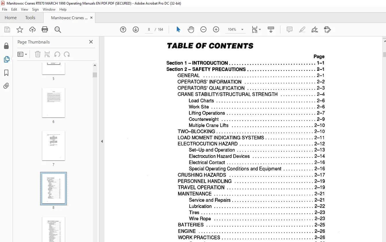
TABLE OF CONTENTS:
Manitowoc Grove Crane RT870 Operator’s & Service Handbook Manual – PDF DOWNLOAD
Section 1 – INTRODUCTION 1-1
Section 2- SAFETY PRECAUTIONS 2-1
viii
GENERAL 2-1
OPERATORS’ INFORMATION 2-2
OPERATORS’ QUALIFICATION 2-3
CRANE STABILITY/STRUCTURAL STRENGTH 2-4
Load Charts 2-6
Work Site 2-6
Lifting Operations 2-7
Counterweight , 2-9
Multiple Crane Lifts 2-10
TWO-BLOCKING 2-1 O
LOAD MOMENT INDICATING SYSTEMS 2-11
ELECTROCUTION HAZARD 2-12
Set-Up and Operation 2-13
Electrocution Hazard Devices 2-14
Electrical Contact 2-16
Special Operating Conditions and Equipment 2-16
CRUSHING HAZARDS 2-17
PERSONNEL HANDLING 2-19
TRAVEL OPERATION 2-19
MAINTENANCE 2-21
Service and Repairs 2-21
Lubrication 2-22
Tires 2-23
Wire Rope 2-23
BATTERIES 2-25
ENGINE 2-26
WORK PRACTICES 2-26
Crane Access 2-26
Job Preparation 2-27
Working 2-27
Lifting , 2-29
Hand Signals , 2-30
TRANSPORTING THE CRANE 2-31
SHUT-DOWN _ , 2-32
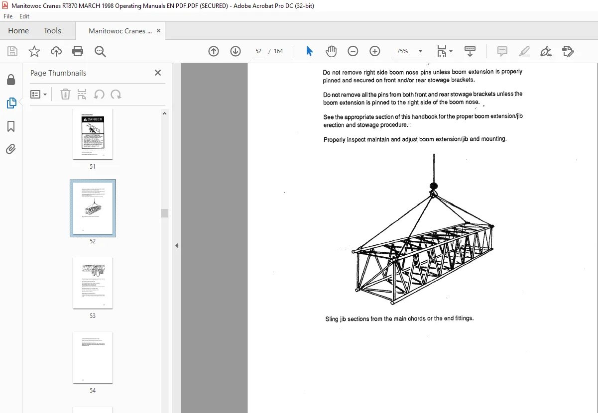
BOOM EXTENSION/JIB 2-33
COLD WEATHER OPERATION 2-35
TABLE OF CONTENTS (continued}
Page
Section 3-CAB CONTROLS AND INDICATORS ~1
ENGINE CONTROLS AND INDICATORS , 3-1
Hand Throttle Lock Control 3-1
Engine Oil Pressure Gauge 3-1
Transmission Oil Temperature Gauge 3-1
Fuel Gauge 3-11
Voltmeter 3-11
Ignition Switch 3-11
Tachometer/Hourmeter 3-11
Cold Start Switch 3-11
Engine Coolant Temperature Gauge 3-12
Foot Throttle Pedal 3-12
Drive Train Distress Indicator 3-12
CRANE CONTROLS AND INDICATORS 3-12
Transmission Shift Lever 3-12
Swing and Telescope Or Auxiliary Hoist Control Lever
(Dual Axis Controller) 3-12
Telescope Or Auxiliary Hoist Control lever
(Single Axis Controller) 3-13
Swing Control Lever (Single Axis Controller) 3-13
Rear Steer Control 3-13
Rear Steer Indicator 3-13
Axle Lockout Override Switch 3-13
Boom Lift Control Lever (Single Axis Controller) 3-14
Main Hoist Control Lever (Single Axis Controller) 3-14
Boom Lift And Main Hoist Control Lever
(Dual Axis Controller) 3-14
Telescope Control Pedal 3-14
Main Hoist Speed Selector Switch 3-14
Main Hoist Hi Speed Indicator 3-14
Auxiliary Hoist Speed Selector Switch 3-14
Auxiliary Hoist Hi Speed Indicator 3-15
Auxiliary Hoist On Off Switch 3–15
Hoist Boost Control Switch 3-15
Hoist Boost Indicator 3-15
Hoist Rotation Indicators 3-15
Third Wrap Indicator light 3-15
Crane Function Power Switch 3-15
Range Selector Switch 3-16
Two Wheel Drive Indicator 3-15
Differential Lock Control Switch 3-16
Differential Locked Indicator 3-16
ix
TABLE OF CONTENTS (continued}
X
Page
Outrigger Selector Panel 3-16
Outrigger Extension/Retraction Switch 3-17
Swing Brake Control Switch 3-17
Swing Brake Pedal 3-17
Swing Brake On Indicator 3-17
Swing Horn Button 3-17
Brake Foot Pedal 3-17
Park Brake Control 3-17
Park Brake Indicator 3-18
Swing Lock Control (Pin Type) 3-18
Swing Lock Control (Positive Lock Type) 3-18
Hi Speed Glide Control Switch 3-18
Hi Speed Glide Indicator 3-18
Steering Pump Failure Indicator 3-18
High Hydraulic Oil Temperature Indicator 3-18
Air Pressure Gauge 3-19
Low Air Pressure Indicator 3-19
Outer Mid Pinning Switch 3-19
Outer Mid Pin Disengaged Indicator 3-19
Outer Mid Pin Engaged Indicator 3-19
Inner Mid Pinning Switch 3-19
Inner Mid Pin Disengaged Indicator 3-20
Inner Mid Pin Engaged Indicator 3-20
LMI Console 3-20
ACCESSORY CONTROLS AND INDICATORS 3-20
Tow Winch Control Lever 3-20
Work Light Switch 3-20
Beacon Light Switch 3-20
Boom Flood Lights Switch 3-20
Lights Switch 3-21
Fire Extinguisher 3-21
Horn 3-21
Turn Signal Lever 3-21
Four-way Flasher Switch 3-21
Steering Column Tiltff elescope Lever 3-21
Right Turn Signal Indicator 3-21
Left Turn Signal Indicator 3-22
Cab Interior Light 3-22
Spotlight {Not Shown) 3-22
Armrest Adjustment Lever 3-22
Skylight Wiper 3-22
Windshield Wiper Switch 3-22
TABLE OF CONTENTS (continued}
Page
Bubble Level Indicator 3-23
Turntable Greaser Button 3-23
Heater Temperature Control (Hydraulic Heater/
Air Conditioner) 3-23
Heater Fan Speed Switch (Hydraulic Heater/
Air Conditioner) 3-23
Heater Fan Mode Switch (Hydraulic Heater/
Air Conditioner) 3-23
Air Control Lever (Hydraulic Heater/Air
Conditioner) 3-23
Air Flow Control Lever (Hydraulic Heater/
Air Conditioner) 3-23
Heater Air Temperature Control (Propane Heater) 3-24
Heater Air Flow Control (Propane Heater) 3-24
Heater Air Circulation Control (Propane Heater) 3-24
Heater Control Switch (Propane Heater) 3-24
Heating Indicator Light (Propane Heater) 3-24
Heating Fuse (Propane Heater) 3-25
Flame Switch Indicator Light (Propane Heater) 3-25
Section 4- OPERATING PROCEDURES 4-1
PRE-STARTING CHECKS 4-1
Fuel Supply 4-1
Engine Oil – 4-1
Engine Coolant 4-1
Batteries 4-1
Signal and Ru,nning Lights 4-1
Foot and Parking Brakes 4-1
Daily Lubrication 4-1
Hydraulic Reservoir and Filter 4-2
Tires 4-2
Wire Rope 4-2
Hook Block 4-2
Swingaway Extension 4-2
Air Cleaner 4-2
COLD WEATHER OPERATION 4-3
ENGINE OPERATION 4-3
Starting Procedure 4-3
Cold Weather Starting 4-4
Idling the Engine· 4-5
Racing the Engine 4-5
Shutdown Procedure 4-5
Battery Disconnect · 4-6
CRANE TRAVEL OPERATION 4-6
Travel-General 4-6
Extended Travel 4-8
Moving the Crane 4-8
Steering 4-9
Front Wheel Steering 4-9
Rear Wheel Steering 4-9
Four Wheel Steering 4-9
Crabbing 4-10
Traveling-Forward 4-10
Traveling-Reverse 4-11
Four Wheel Drive Operation 4-11
Proper Operation of Differential Lack 4-12
General 4-12
Operation 4-13
Proper Operation of Axle Oscillation Lockouts 4-14
Crane Towing Instructions 4-14
Before Towing 4-15
Before Operating the Crane 4-15
GENERAL CRANE OPERATION 4-16
Pump Drive 4-16
Setting the Park Brake When the Crane is on Outriggers 4-17
Control Lever Operation 4-17
Preload Check 4-18
USING YOUR LOAD CHART 4-18
CRANE FUNCTIONS 4-20
Setting the Outriggers 4-21
Engaging the Lock Pin 4-22
Stowing the Outriggers 4-23
Stowing the Lock Pin 4-24
Swinging the Boom 4-25
Elevating and Lowering the Boom 4-26
Elevating the Boom 4-26
Lowering the Boom 4-26
Emergency Boom Operating Procedures 4-27
Telescoping the Boom 4-28
Extending the Boom , 4-28
Retracting the Boom 4-28
lowering and Raising the Cable 4-29
Lowering the Cable 4-29
Raising the Cable 4-29
Stowing and Parking , 4-30
T’ABI £ OF CONTENTS tcontlnuedJ
Page
OPTIONAL EQUIPMENT OPERATION 4-31
Boom Latching System 4-31
Engine Cold Start Operation 4-31
Propane Heater · 4-32
Starting 4-32
Operating 4-32
Stopping · 4-32
Hi-Speed Glide System 4-33
Tow Winch 4-33
OPERATIONAL AIDS 4-34
Load Moment Indicating System 4-34
Section 5 – LUBRICATION 5-1
GENERAL 5-1
LUBRICATION POINTS 5-1
WIRE ROPE LUBRICATION 5-18
Section 6-SET UP AND INSTALLATION PROCEDURES 6-1
GENERAL 6-1
INSTALLING CABLE ON THE HOIST 6-1
CABLE REEVING 6-2
DEAD-END RIGGING/WEDGE SOCKETS 6-2
Installing the Wedge and Socket 6-4
ERECTING ANO STOWING THE SWINGAWAY
BOOM EXTENSION 6-6
Erecting 6-6
Stowing 6- 16
Setting the Offset 6-17
Setting the Telescoping Extension Length 6-20
Extending 6-20
Retracting 6-21
COUNTERWEIGHT REMOVAL AND INSTALLATION
(WITHOUT REMOVAL SYSTEM) ~ 6-22
Removal 6-22
Installation 6-23
COUNTERWEIGHT REMOVAL AND INSTALLATION
(WITH REMOVAL SYSTEM) 6-25
Removal 6-25
Installation , 6-28
Customer Support: [email protected]
S.V