Manitowoc Grove Crane RT875C Operator`s & Safety Handbook Manual
$25.95
The Manitowoc Grove Crane RT875C Operator’s & Safety Handbook is a comprehensive manual in PDF format. It offers essential guidance for operating the RT875C model, emphasizing safety protocols. Download for crucial insights into crane functions, maintenance, and adherence to safety standards.
Description
Manitowoc Grove Crane RT875C Operator`s & Safety Handbook Manual – PDF DOWNLOAD
FILE DETAILS:
Manitowoc Grove Crane RT875C Operator`s & Safety Handbook Manual – PDF DOWNLOAD
Language : English
Pages :173
Downloadable : Yes
File Type : PDF
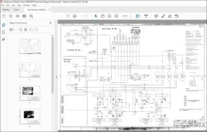
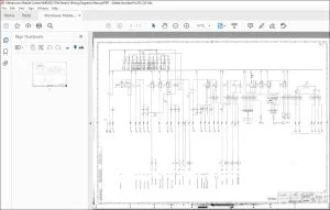
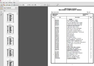
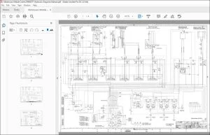
IMAGES PREVIEW OF THE MANUAL:
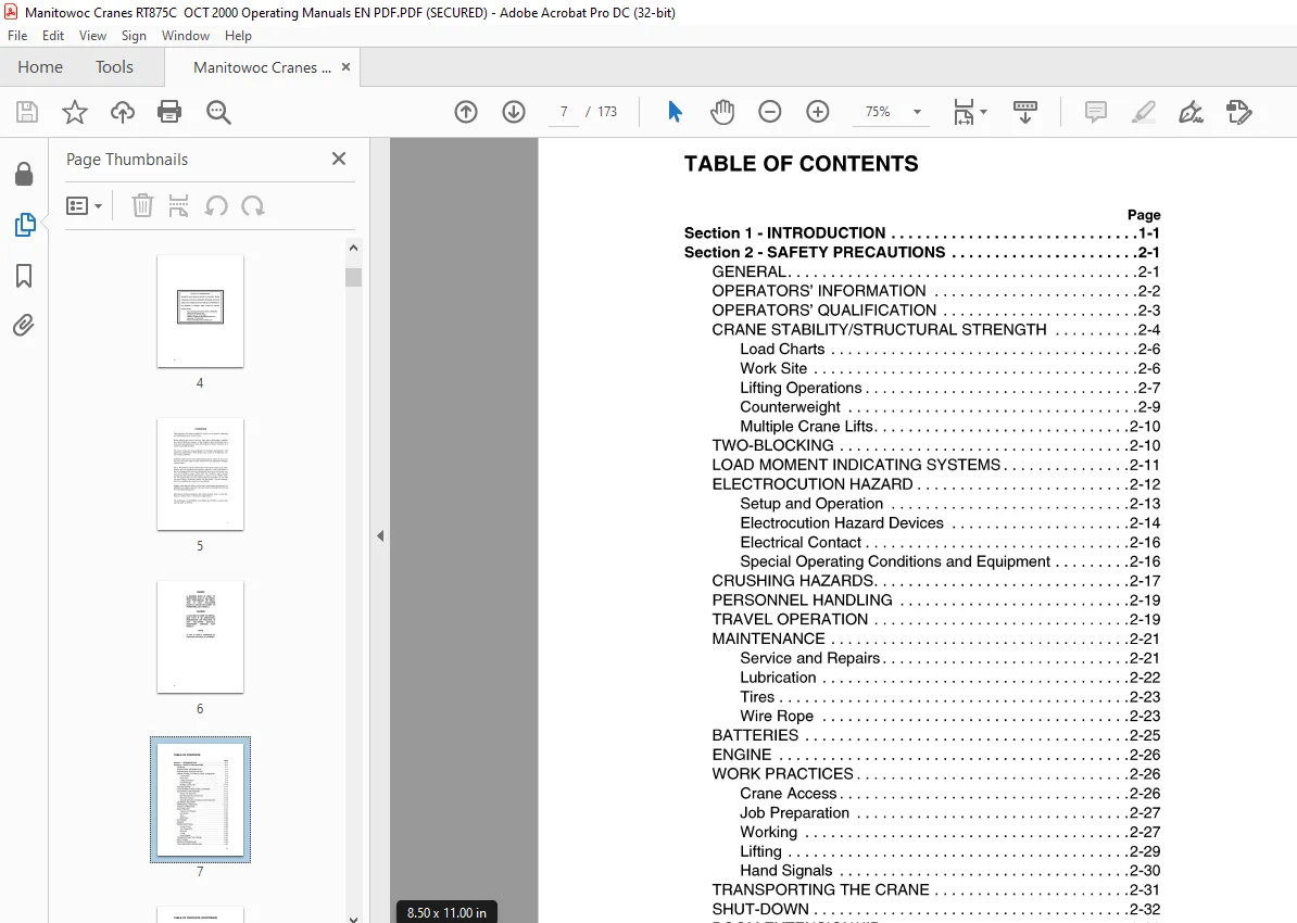
TABLE OF CONTENTS:
Manitowoc Grove Crane RT875C Operator`s & Safety Handbook Manual – PDF DOWNLOAD
Section 1 – INTRODUCTION 1-1
Section 2 – SAFETY PRECAUTIONS 2-1
GENERAL 2-1
OPERATORS’ INFORMATION 2-2
OPERATORS’ QUALIFICATION 2-3
CRANE STABILITY/STRUCTURAL STRENGTH 2-4
Load Charts 2-6
Work Site 2-6
Lifting Operations 2-7
Counterweight 2-9
Multiple Crane Lifts 2-1 O
TWO-BLOCKING 2-10
LOAD MOMENT INDICATING SYSTEMS 2-11
ELECTROCUTION HAZARD 2-12
Setup and Operation 2-13
Electrocution Hazard Devices 2-14
Electrical Contact 2-16
Special Operating Conditions and Equipment 2-16
CRUSHING HAZARDS 2-17
PERSONNEL HANDLING 2-19
TRAVEL OPERATION 2-19
MAINTENANCE 2-21
Service and Repairs 2-21
Lubrication 2-22
Tires 2-23
Wire Rope 2-23
BATTERIES 2-25
ENGINE 2-26
WORK PRACTICES 2-26
Crane Access 2-26
Job Preparation 2-27
Working 2-27
Lifting 2-29
Hand Signals 2-30
TRANSPORTING THE CRANE 2-31
SHUT-DOWN 2-32
BOOM EXTENSION/JIB 2-33
COLD WEATHER OPERATION 2-35
vii
TABLE OF CONTENTS (CONTINUED)
Page
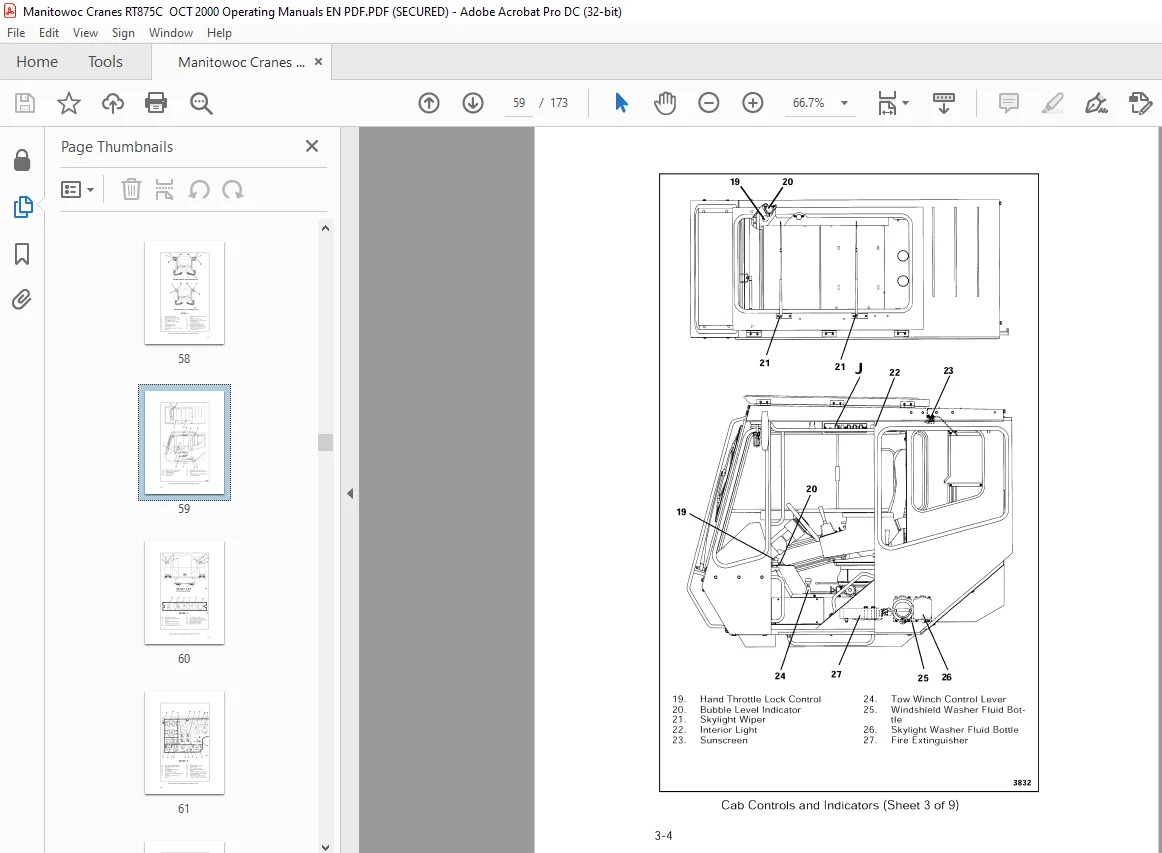
Section 3 – CAB CONTROLS AND INDICATORS 3-1
ENGINE CONTROLS AND INDICATORS 3-1
Hand Throttle Lock Control 3-1
Engine Oil Pressure Gauge 3-1
Transmission Oil Temperature Gauge 3-1
Fuel Gauge 3-11
Voltmeter 3-11
Ignition Switch 3-11
Tachometer/Hourmeter 3-11
Cold Start Switch 3-12
Engine Coolant Temperature Gauge 3-12
Foot Throttle Pedal 3-12
Drive Train Distress Indicator 3-12
CRANE CONTROLS AND INDICATORS 3-12
Transmission Shift Lever 3-12
Swing and Telescope Or Auxiliary Hoist Control Lever
(Dual Axis Controller) 3-13
Telescope Or Auxiliary Hoist Control Lever
(Single Axis Controller) 3-13
Swing Control Lever (Single Axis Controller) 3-13
Rear Steer Control 3-13
Rear Steer Indicator 3-13
Axle Lockout Override Switch 3-13
Boom Lift Control Lever (Single Axis Controller) 3-14
Main Hoist Control Lever (Single Axis Controller) 3-14
Boom Lift And Main Hoist Control Lever
(Dual Axis Controller) 3-14
Telescope Control Pedal 3-14
Main Hoist Speed Selector Switch 3-14
Main Hoist Hi Speed Indicator 3-14
Auxiliary Hoist Speed Selector Switch 3-14
Auxiliary Hoist Hi Speed Indicator 3-15
Auxiliary Hoist On Off Switch 3-15
Hoist Boost Control Switch 3-15
Hoist Boost Indicator 3-15
Hoist Rotation Indicators 3-15
Third Wrap Indicator Light 3-15
Crane Function Power Switch 3-15
Range Selector Switch 3-16
viii
TABLE OF CONTENTS (CONTINUED)
Page
Two Wheel Drive Indicator 3-16
Differential Lock Control Switch 3-16
Differential Locked Indicator 3-16
Outrigger Selector Panel 3-16
Outrigger Extension/Retraction Switch 3-17
Swing Brake Control Switch 3-17
Swing Brake Pedal 3-17
Swing Brake On Indicator 3-17
Swing Horn Button 3-17
Brake Foot Pedal 3-17
Park Brake Control 3-17
Park Brake Indicator 3-18
Swing Lock Control (Pin Type) 3-18
Swing Lock Control (Positive Lock Type) 3-18
Hi Speed Glide Control Switch 3-18
Hi Speed Glide Indicator 3-18
Steering Pump Failure Indicator 3-18
High Hydraulic Oil Temperature Indicator 3-18
Air Pressure Gauge 3-19
Low Air Pressure Indicator 3-19
Outer Mid Pinning Switch 3-19
Outer Mid Pin Disengaged Indicator 3-19
Outer Mid Pin Engaged Indicator 3-19
Inner Mid Pinning Switch 3-20
Inner Mid Pin Disengaged Indicator 3-20
Inner Mid Pin Engaged Indicator 3-20
LMI Console 3-20
ACCESSORY CONTROLS AND INDICATORS 3-20
Tow Winch Control Lever 3-20
Work Light Switch 3-20
Beacon Light Switch 3-20
Boom Flood Lights Switch 3-20
Lights Switch 3-21
Fire Extinguisher 3-21
Horn 3-21
Turn Signal Lever 3-21
Four-way Flasher Switch 3-21
ix
TABLE OF CONTENTS (CONTINUED)
Page
Steering Column Tilt/Telescope Lever 3-21
Right Turn Signal Indicator 3-21
Lett Turn Signal Indicator 3-22
Cab Interior Light 3-22
Spotlight (Not Shown) 3-22
Armrest Adjustment Lever 3-22
Skylight Wiper 3-22
Windshield Wiper Switch 3-22
Bubble Level Indicator 3-23
Turntable Greaser Button 3-23
Heater Temperature Control (Hydraulic Heater/
Air Conditioner) 3-23
Heater Fan Speed Switch (Hydraulic Heater/
Air Conditioner) 3-23
Heater Fan Mode Switch (Hydraulic Heater/
Air Conditioner) 3-23
Air Control Lever (Hydraulic Heater/Air
Conditioner) 3-23
Air Flow Control Lever (Hydraulic Heater/
Air Conditioner) 3-23
Heater Air Temperature Control (Propane Heater) 3-24
Heater Air Flow Control (Propane Heater) 3-24
Heater Air Circulation Control (Propane Heater) 3-24
Heater Control Switch (Propane Heater) 3-24
Heating Indicator Light (Propane Heater) 3-24
Heating Fuse (Propane Heater) 3-25
Flame Switch Indicator Light (Propane Heater) 3-25
Section 4 – OPERATING PROCEDURES 4-1
PRE-STARTING CHECKS 4-1
Fuel Supply 4-1
Engine Oil 4-1
Engine Coolant 4-1
Batteries 4-1
Signal and Running Lights 4-1
Foot and Parking Brakes 4-1
Daily Lubrication 4-1
Hydraulic Reservoir and Filter 4-2
Tires 4-2
Wire Rope 4-2
X
TABLE OF CONTENTS (CONTINUED)
Page
Hook Block 4-2
Swingaway Extension 4-2
Air Cleaner 4-2
COLD WEATHER OPERATION 4-3
ENGINE OPERATION 4-3
Starting Procedure 4-3
Cold Weather Starting 4-4
Idling the Engine 4-5
Racing the Engine 4-5
Shutdown Procedure 4-5
Battery Disconnect 4-6
CRANE TRAVEL OPERATION 4-6
Travel-General 4-6
Extended Travel 4-8
Moving the Crane 4-8
Steering 4-9
Front Wheel Steering 4-9
Rear Wheel Steering 4-9
Four Wheel Steering 4-9
Crabbing 4-1 0
Traveling-Forward 4-10
Traveling-Reverse 4-11
Four Wheel Drive Operation 4-11
Proper Operation of Differential Lock 4-12
General 4-12
Operation 4-13
Proper Operation of Axle Oscillation Lockouts 4-14
Crane Towing Instructions 4-14
Before Towing 4-15
Before Operating the Crane 4-15
GENERAL CRANE OPERATION 4-16
Pump Drive 4-16
Setting the Park Brake When the Crane is on Outriggers 4-17
Control Lever Operation 4-17
Preload Check 4-17
USING YOUR LOAD CHART 4-18
CRANE FUNCTIONS 4-20
xi
TABLE OF CONTENTS (CONTINUED)
Page
Setting the Outriggers 4-21
Engaging the Lock Pin 4-22
Stowing the Outriggers 4-23
Stowing the Lock Pin 4-24
Swinging the Boom 4-25
Elevating and Lowering the Boom 4-26
Elevating the Boom 4-26
Lowering the Boom 4-26
Emergency Boom Operating Procedures 4-27
Telescoping the Boom 4-28
Extending the Boom 4-28
Retracting the Boom 4-28
Lowering and Raising the Cable 4-29
Lowering the Cable 4-29
Raising the Cable 4-29
Stowing and Parking 4-30
OPTIONAL EQUIPMENT OPERATION 4-31
Boom Latching System 4-31
Engine Cold Start Operation 4-31
Propane Heater 4-32
Starting 4-32
Operating 4-32
Stopping 4-32
Hi-Speed Glide System 4-33
Tow Winch 4-33
OPERATIONAL AIDS 4-34
Load Moment Indicating (LMI) system 4-34
Section 5 – LUBRICATION 5-1
GENERAL 5-1
LUBRICATION POINTS 5-1
WIRE ROPE LUBRICATION 5-18
Section 6 – SET UP AND INSTALLATION PROCEDURES 6-1
GENERAL 6-1
INSTALLING CABLE ON THE HOIST 6-1
CABLE REEVING 6-2
DEAD-END RIGGING/WEDGE SOCKETS 6-2
Installing the Wedge and Socket 6-4
xii
TABLE OF CONTENTS (CONTINUED)
Page
ERECTING AND STOWING THE SWINGAWAY
BOOM EXTENSION 6-6
Erecting 6-6
Stowing 6-16
Setting the Offset 6-17
Setting the Telescoping Length 6-20
Extending 6-20
Retracting 6-21
COUNTERWEIGHT REMOVAL AND INSTALLATION
(WITHOUT REMOVAL SYSTEM) 6-22
Removal 6-22
Installation 6-23
COUNTERWEIGHT REMOVAL AND INSTALLATION
(WITH REMOVAL SYSTEM) 6-25
Removal 6-25
Installation 6-28
xiii
Questions? Email us: [email protected]
S.M