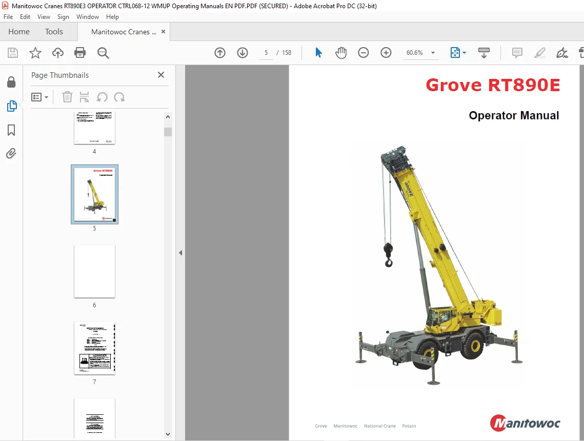
Manitowoc Grove Crane RT890E Operator Manual 068-12 PDF
$26.95
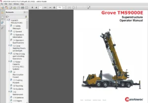
The Manitowoc Grove Crane RT890E Operator Manual (068-12) in PDF format is a vital resource for RT890E model crane operators. Download for comprehensive guidance on safe and effective crane operation, featuring essential instructions and safety protocols.
Description
Manitowoc Grove Crane RT890E Operator Manual 068-12 – PDF DOWNLOAD
FILE DETAILS:
Manitowoc Grove Crane RT890E Operator Manual 068-12 – PDF DOWNLOAD
Language : English
Pages :158
Downloadable : Yes
File Type : PDF
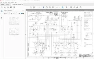
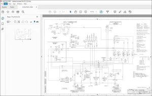
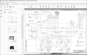
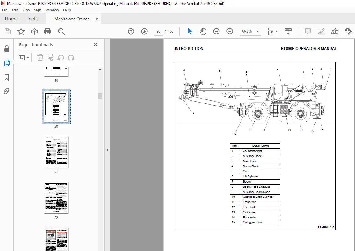
IMAGES PREVIEW OF THE MANUAL:
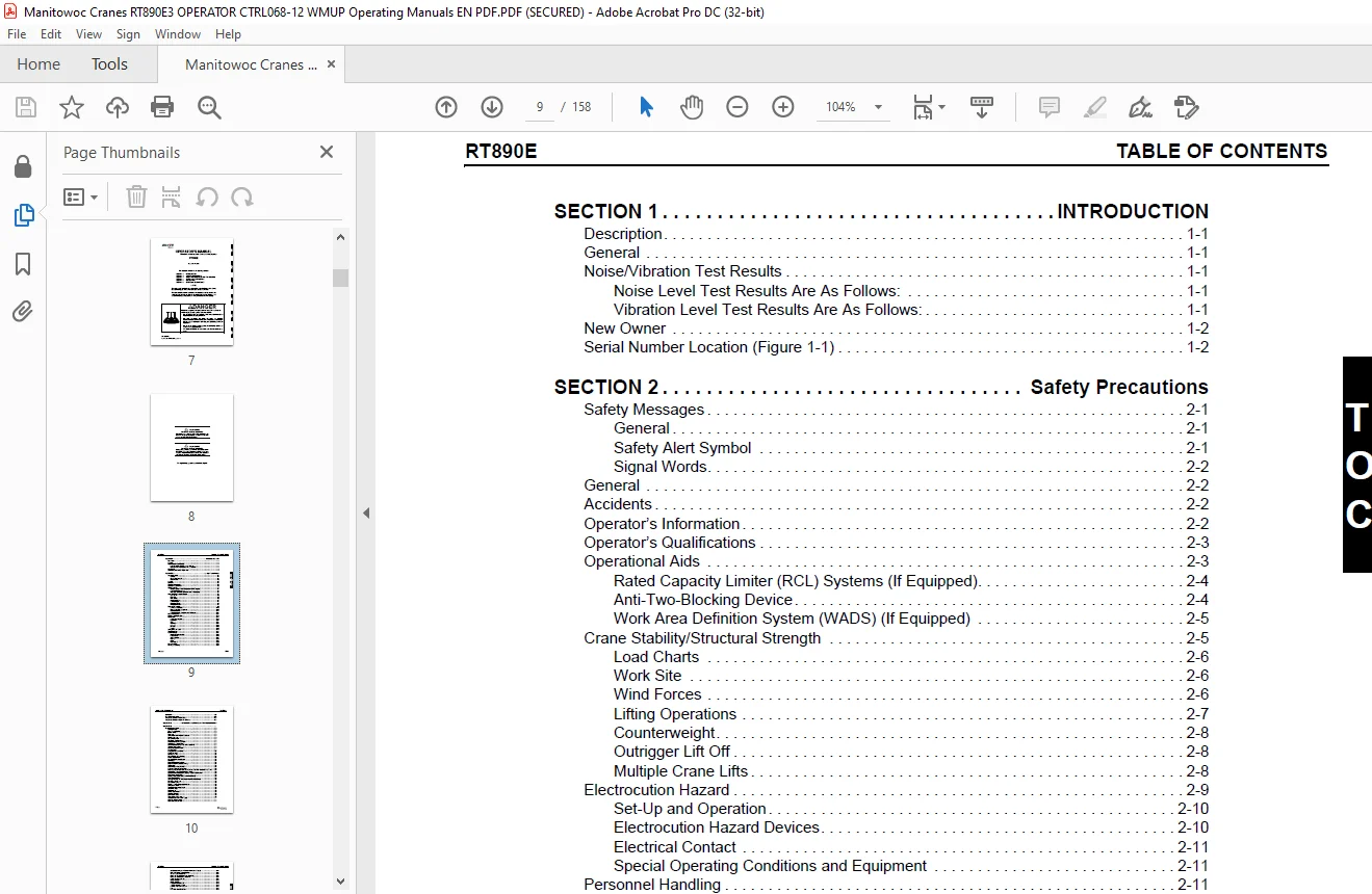
TABLE OF CONTENTS:
Manitowoc Grove Crane RT890E Operator Manual 068-12 – PDF DOWNLOAD
SECTION 1 15
INTRODUCTION 15
Description 15
General 15
Noise/Vibration Test Results 15
Noise Level Test Results Are As Follows: 15
Vibration Level Test Results Are As Follows: 15
New Owner 16
Serial Number Location (Figure 1-1) 16
SECTION 2 21
Safety Precautions 21
Safety Messages 21
General 21
Safety Alert Symbol 21
Signal Words 22
General 22
Accidents 22
Operator’s Information 22
Operator’s Qualifications 23
Operational Aids 23
Rated Capacity Limiter (RCL) Systems (If Equipped) 24
Anti-Two-Blocking Device 24
Work Area Definition System (WADS) (If Equipped) 25
Crane Stability/Structural Strength 25
Load Charts 26
Work Site 26
Wind Forces 26
Lifting Operations 27
Counterweight 28
Outrigger Lift Off 28
Multiple Crane Lifts 28
Electrocution Hazard 29
Set-Up and Operation 30
Electrocution Hazard Devices 30
Electrical Contact 31
Special Operating Conditions and Equipment 31
Personnel Handling 31
Environmental Protection 32
Maintenance 33
Service and Repairs 33
Lubrication 34
Tires 34
Wire Rope 34
Sheaves 36
Batteries 36
Engine 36
Transporting the Crane 37
Travel Operation 37
Work Practices 38
Personal Considerations 38
Crane Access 38
Job Preparation 38
Working 38
Lifting 39
Hand Signals 40
Boom Extension 42
Parking and Securing 42
Shut-Down 42
Cold Weather Operation 42
Temperature Effects on Hook Blocks 43
Temperature Effects on Hydraulic Cylinders 43
SECTION 3 45
OPERATING CONTROLS AND PROCEDURES 45
Controls And Indicators 46
Defroster Switch 46
Hand Throttle Control 46
Ignition Switch 46
Voltmeter 46
Transmission Oil Temperature Gauge 46
Heat Control Knob 46
Fan Control Switch 51
Park Brake Control Switch 51
Air Conditioner Control Switch 51
Swing Brake Control Switch 51
Axle Differential Lock Control Switch (Optional) 51
2-Speed Swing Switch 51
Drive Axle Selector Switch 51
Cab Tilt Switch 51
Outrigger Control Switches 52
Work Light Switch 52
Headlights Switch 52
Boom Lights Switch (Optional) 52
Hazard Lights Switch 52
Hose Reel Brake On Indicator 52
Fuel Gauge 52
Engine Diagnostics Switches 52
Test Mode Switch 52
Idle Switch 52
Engine Coolant Temperature Gauge 52
Tachometer 52
Crane Function Power Switch 52
Outriggers Extend/Retract Switch 53
Rated Capacity Limiter (RCL) and Work Area Definition System Control Panel 53
Auto/Manual Boom Telescope Mode Switch 53
Center Mid/Inner Mid Boom Telescope Section Select Switch 53
Rear Steer Control Switch 53
Auxiliary Hoist Speed Selector Switch (Optional) 53
Swing Control Lever 53
Turn Signal Lever and Windshield Wiper/ Washer Controls 54
Bubble Level Indicator 54
Cab Circulating Fan 54
Electrical System Diagnostic Indicator 54
Swing Brake Pedal 54
Telescope Control Foot Pedal 54
Windshield Wiper 54
Defroster Fan 54
Service Brake Pedal 54
Spotlight (Optional) 54
Foot Throttle Pedal 54
Transmission Shift Lever 54
Turntable Lock Control (Pin Type) 55
Hoist Rotation Indicators 55
Main Hoist Control Lever 55
360 Degree Swing Lock Control (Positive Lock Type) 55
Main Hoist Speed Selector Switch 55
-29° C Indicator (Optional) 55
Luffing Jib Raise/Lower Switch (Optional) 55
Luffing Jib On/Off Switch (Optional) 55
Seat Switch (Not Shown) 55
Cab Dome Light 55
Fire Extinguisher 56
Boom Lift Control Lever 56
12 VDC Accessory Outlet 56
Auxiliary Hoist Control Lever 56
Horn 56
Right Turn Signal Indicator 56
Left Turn Signal Indicator 56
Rear Wheels Not Centered Indicator 56
Hoist 3rd Wrap Indicator (Optional w/CE) 56
Engine Stop Indicator 56
Engine Warning Indicator 56
Engine Service Indicator 56
Wait To Start Indicator 56
Low Brake Pressure Indicator 56
Transmission Service Indicator (XMSN) 56
Water In Fuel Indicator 57
Boom Not Sync Indicator 57
Throttle Mode Switch 57
Hourmeter (Not Shown) 57
Skylight Wiper (Not Shown) 57
Backup Alarm (Not Shown) 57
Armrest Switch (Not Shown) 57
Boom Telescope Mode A/B Select Switch 57
Low Steer Pressure Indicator (CE Option) 57
Boom Lift/Main Hoist Controller (Dual Axis Option) 57
Telescope/Auxiliary Hoist/Swing Controller (Dual Axis Option) 58
Operating Procedures 59
Pre-Starting Checks 59
Fuel Supply 59
Engine Oil 59
Engine Coolant 59
Batteries 59
Signal and Running Lights 59
Foot and Parking Brakes 59
Daily Lubrication 59
Hydraulic Reservoir and Filter 59
Tires 59
Wire Rope 59
Hook Block 59
Air Cleaner 59
Cold Weather Operation 59
Operation Below -40°C 59
Starting Procedure 60
Battery Disconnect Switch 60
Warm Engine 60
Cold Engine 61
Idling the Engine 61
Racing the Engine 61
Shutdown Procedure 61
Crane Travel Operation 61
Traveling — General 61
Travel on Slopes 62
Traveling with Elevated Boom 63
Traveling with Boom Extension and/or Inserts Erected 63
33 ft (10 1 m)/56 ft (17 1 m) Extension Plus 16 ft (4 9 m) or 32 ft (10 m) Inserts 63
Extended Travel 63
Traveling — Forward 64
Traveling — Reverse 64
Steering 64
Front Wheel Steering 64
Rear Wheel Steering 64
Four Wheel Steering 64
Crabbing 65
Four-Wheel Drive Operation 65
Differential Lock Operation (Optional) 65
General 65
Operation 66
Axle Oscillation Lockouts Operation 66
General Crane Operation 66
Pump Drive 66
Control Lever Operation 66
Preload Check 67
Using Your Load Chart 67
Proper Leveling of the Crane 68
Bubble Level Adjustment 68
Crane Functions 68
Setting the Outriggers 68
Engaging the Mid-Extend Lock Pin 69
Stowing the Outriggers 69
Stowing the Mid-Extend Lock Pin 69
Swinging the Boom 70
Elevating and Lowering the Boom 70
Elevating the Boom 70
Lowering the Boom 70
Telescoping the Boom 70
Extending the Boom 70
Retracting the Boom 71
Lowering and Raising the Hoist Cable 71
Lowering the Cable 71
Raising the Cable 71
Hoist Speed Range Selection 71
Raising and Lowering the Hydraulic Boom Extension 71
Raising the Hydraulic Boom Extension 71
Lowering the Hydraulic Boom Extension 72
Operational Aids 72
Rated Capacity Limiter (RCL) System 72
Control Lever Lockout System 73
Stowing and Parking 73
Unattended Crane 74
SECTION 4 75
SET-UP AND INSTALLATION 75
Installing Cable On The Hoist 75
Cable Reeving 76
Dead-End Rigging/Wedge Sockets 77
Installing Wedge and Socket 77
Counterweight and Auxiliary Hoist 81
Removal 81
Installation 81
Counterweight Without Auxiliary Hoist 81
Removal 81
Installation 84
Installing the Bi-Fold Manual Boom Extension 84
Checking the Transport Condition 86
Transport condition with lattice extension folded at the side 86
If 23 ft (7 m) section and 33 ft (10 1 m) section are folded at the side: 86
If the 23 ft (7 m) section only is folded at the side: 86
Boom Extension Erecting and Stowing Procedure 86
General Warnings 86
Preparing the Crane for Boom Extension Erection Procedure 86
Requirements for Boom Extension Erection 86
Requirements for Stowing the Boom Extension 87
Securing Lattice Extension With Tag Line (Rope) 87
Erecting Procedure 87
33 ft (10 1 m) Boom Extension 87
Relieving the Load on Bearing Points 91
56 ft (17 1 m) Boom Extension 93
Stowing Procedure, Boom Extensions 94
Stowing 23 ft (7 m) Bi-fold Extension 94
33 ft (10 1 m) Lattice Boom Extension 95
Reeve the hoist cable as described in this section 99
Hose Drum for Hydraulic Luffing Boom Extension 100
Locking Devices For Transportation 100
Inserting Anti-Twist Device 100
Removing Anti-Twist Device 100
Hydraulic Connection 100
Position For Working With The Lattice Extension 101
Position For Working With the Main Boom 101
Raising and Lowering the Hydraulic Boom Extension 101
When erecting 101
During operation 101
Transportation on a Separate Vehicle 102
Connecting and Disconnecting the Hydraulic Boom Extension 102
Connecting 102
Establish a Hydraulic Connection Between the Lattice Extension and the Main Boom 102
Disconnect the Hydraulic Connection Between the Lattice Extension and the Main Boom 102
Establish an electrical connection between the lattice extension and the main boom 103
Establish An Electrical Connection Between the Lattice Extension and Anti-Two Block Switch 104
Disconnect the Electrical Connection Between the Lattice Extension and the Main Boom 104
Hydraulic Connection at the Boom Extension 104
Transport Condition of the Connections 104
At the 72 ft (22 0 m) Boom Extension 104
Establishing a Connection 104
Disconnecting 104
At the 89 ft (27 m) Boom Extension 104
Establishing a Connection 104
Disconnecting 104
Lifting Limit Switch on the Lattice Extension 105
Overriding Connection on Main Boom 105
On 33 ft (10 1 m) swingaway lattice extension (Figure 4-74) 106
On the 56 ft (17 1 m) Two-Stage Swingaway Lattice Extension 106
Folding Out/In the Deflection Sheaves on the 33 ft (10 1 m) Section 106
Folding Rear Deflection Sheave 107
Folding Out Deflection Sheave (Figure 4-78) 107
Folding In Deflection Sheave 107
Positioning/Remove the Hoist Cable 107
Removing Hoist Cable 108
Setting the Folding Swingaway Extension Offset 108
Removing the Bi-Fold Manual Boom Extension 109
Installing/Removing 16 ft (4 9 m) Sections 109
Installing the 16 ft (4 9 m) Sections 110
Removing the 16 ft (4 9 m) Sections 110
Boom Extension (Additional Equipment) 110
Identification and Slinging Points 110
Identification 110
Serial numbers on the 16 ft (4 9 m) sections 110
Slinging Points 110
Assembly Of Boom Extensions 111
Electrical Connection at the Boom Extension 111
Transport Condition of the Connection 111
At the 72 ft (22 0 m) Boom Extension 112
At the 89 ft (27 1 m) Boom Extension 112
Unfolding/Folding the Deflection Sheave on the 16 ft (4 9 m) Section 112
Folding Out Deflection Sheave 113
Folding In Deflection Sheave 113
Positioning/Removing the Hoist Cable 113
Positioning Hoist Cable 113
Removing Hoist Cable 113
Traveling with Hydraulic Luffing or Manually Offsettable Boom Extension and/or Inserts Erected 114
33 ft (10 1 m)/56 ft (17 1 m) Extension Plus 16 ft (4 9 m) or 32 ft (10 m) Inserts 114
Adjustment Procedure for Stowage Brackets for Hydraulic Luffing Jib 114
Auxiliary Single-Sheave Boom Nose (Additional Equipment) 115
Identification 115
Installing/Removing Auxiliary Single-Sheave Boom Nose 115
Installing Auxiliary Single-Sheave Boom Nose 115
Removing the Auxiliary Single-Sheave Boom Nose 116
Rigging The Auxiliary Single-Sheave Boom Nose 116
Rigging in Transport Position 116
Rigging in Working Position 117
Attaching and Removing Hoist Cable 118
Possible Reeving Methods on the Auxiliary Single-Sheave Boom Nose 118
Lifting Limit Switch 118
In Operation 118
During Transport 118
Raising And Setting Down The Main Boom With Rigged Lattice Extension 119
Telescoping With Rigged Lattice Extension 119
Operating With The Lattice Extension 119
Procedure if the Permissible Wind Speed is Exceeded 120
Monthly Maintenance Work 120
Pins 120
Lubricating Joint on 33 ft (10 1 m) Section 120
Lubricate the derricking cylinder in 33 ft (10 1 m) section 121
SECTION 5 123
LUBRICATION 123
General 123
Environmental Protection 123
Lubrication Intervals 123
Arctic Conditions – Below 0°F (-18°C) 123
Arctic Conditions Down To -40°F 124
All Weather Package & Lubricants 124
Standard Lubricants Package 124
Surface Protection for Cylinder Rods 124
Wire Rope Lubrication 125
Lubrication Points 125
CraneLUBE 126
Safety 126
Steering and Suspension 127
Axles 129
Drive Train 131
Drive Train (continued) 133
Turntable 135
Cab Tilt 137
Outriggers 139
Boom 141
Boom (continued) 143
Boom (continued) 145
Hoist 147
Hydraulic 149
Instructions for Accessing Lubrication Points on Boom 151
SECTION 6 153
MAINTENANCE CHECKLIST 153
General 153
Instructions 153
Daily or 10 Hour Check List 153
Weekly or 50 Hour Check List 154
CTRL516-02_Warm-up_Procedures–Supplement pdf 0
Crane Warm-up Procedures 3
Engine 3
Transmission 3
Hoist 3
Swing Drive and Turntable Bearing 4
Axles 4
Hydraulic Oil System 4
Need help? Contact: [email protected]
S.M