Manitowoc Grove Crane RT9150E Operator Manual PDF
$28.95
Description
Manitowoc Grove Crane RT9150E Operator Manual – PDF DOWNLOAD
FILE DETAILS:
Manitowoc Grove Crane RT9150E Operator Manual – PDF DOWNLOAD
Language : English
Pages : 326
Downloadable : Yes
File Type : PDF
IMAGES PREVIEW OF THE MANUAL:
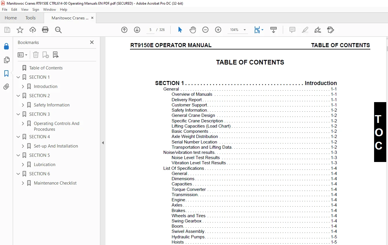
TABLE OF CONTENTS:
Manitowoc Grove Crane RT9150E Operator Manual – PDF DOWNLOAD
Table of Contents 5
SECTION 1 13
Introduction 13
General 13
Overview of Manuals 13
Delivery Report 13
Customer Support 13
New Owners 14
Safety Information 14
General Crane Design 14
Specific Crane Description 14
Lifting Capacities (Load Chart) 14
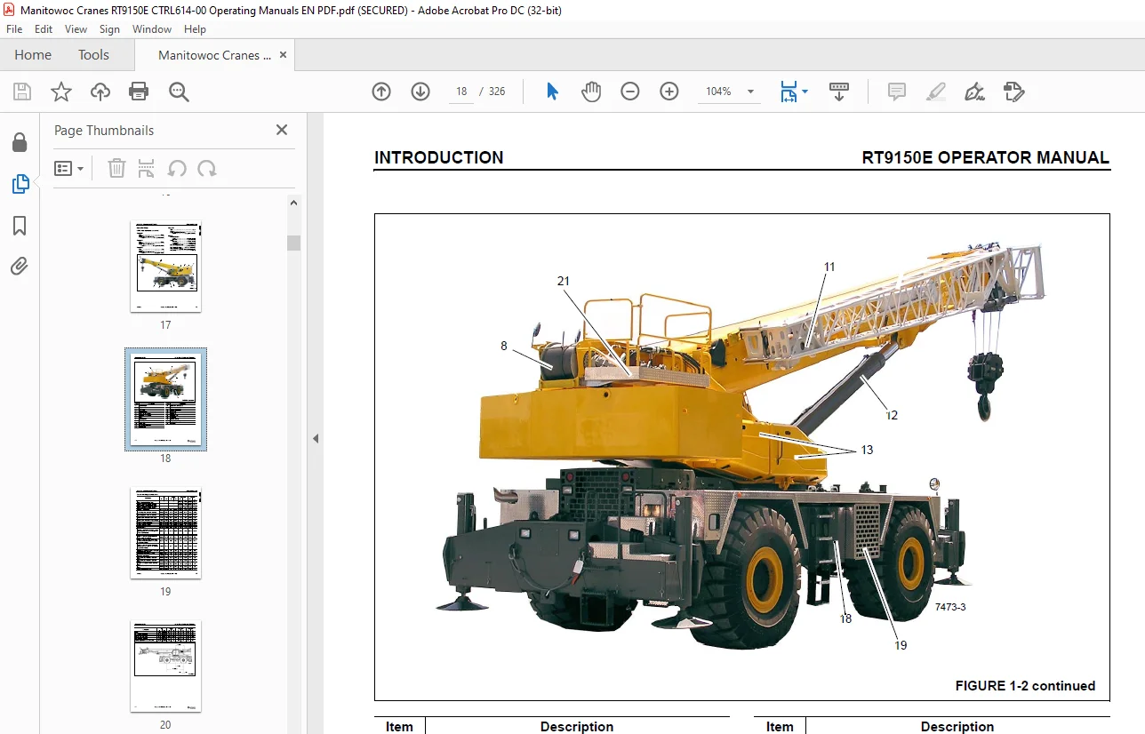
Basic Components 14
Axle Weight Distribution 14
Serial Number Location 14
Transportation and Lifting Data 14
Noise/vibration test results 15
Noise Level Test Results 15
Vibration Level Test Results 15
List Of Specifications 16
General 16
Dimensions 16
Capacities 16
Torque Converter 16
Transmission 16
Engine 16
Cummins QSC 16
Axles 16
Brakes 16
Wheels and Tires 16
Swing Gearbox 16
Boom 16
Swivel Assembly 16
Hydraulic Pumps 17
Pump #1 17
Pump #2 17
Pump #3 17
Pump #4 17
Hoists 17
Wire Rope (Hoist Cable) 21
General 21
Environmental Conditions 21
Dynamic Shock Loads 21
Lubrication 21
Precautions and Recommendations During Inspection or Replacement 21
Wire Rope Inspection (Running Ropes and Pendant Cables) 22
Keeping Records 22
Frequent Inspection 22
Periodic Inspection 23
Wire Rope Inspection/Replacement (All Wire Rope) 23
Seizing Wire Rope 23
Method 1 23
Method 2 24
Installing 35×7 Class Wire Rope 24
SECTION 2 27
Safety Information 27
Safety Messages 27
General 27
Safety Messages 28
General 28
Safety Alert Symbol 28
Signal Words 28
General 28
Warning Signs 28
Accidents 28
Operator Information 29
Operator Qualifications 29
Operational Aids 30
Rated Capacity Limiter (RCL) Systems (If Equipped) 30
Anti-Two-Blocking Device 31
Working Area Limiter (If Equipped) 31
Crane Stability/Structural Strength 32
Load Charts 33
Work Site 33
Wind Forces 33
Wind Speeds 34
Determination of 3-second wind gust speed at boom tip height: 36
Size and Shape of the load: 36
Determining Wind Drag Coefficient (Cd) 37
Maximum Permissible Wind Speed 38
Example and Sample Calculations (metric) 40
Example 1: Crane Configuration: 40
Load example 1 1: 41
Load example 1 2: 41
Load example 1 3a: 41
Load example 1 3b: 41
Example and Sample Calculations (Non-metric) 44
Example 2: 44
Load example 2 1: 45
Load example 2 2: 45
Load example 2 3a: 45
Load example 2 3b: 45
Lifting Operations 46
Counterweight 47
Outrigger Lift Off 47
Multiple Crane Lifts 47
Tilt-Up Panel Lifting 47
Pile Driving and Extracting 48
Crane Equipment 48
Crane Inspection 48
Electrocution Hazard 49
Set-Up and Operation 50
Electrocution Hazard Devices 50
Electrical Contact 51
Special Operating Conditions and Equipment 51
Personnel Handling 51
Environmental Protection 52
Maintenance 53
Service and Repairs 53
Lubrication 54
Tires 54
Hoist Rope 54
Synthetic Hoist Rope 54
Wire Rope 55
Sheaves 56
Batteries 56
Engine 57
Transporting the Crane 57
Travel Operation 57
Work Practices 58
Personal Considerations 58
Crane Access 58
Job Preparation 59
Working 59
Lifting 60
Hand Signals 61
Jib 63
Parking and Securing 63
Shut-Down 63
Cold Weather Operation 63
Temperature Effects on Hook Blocks 64
Temperature Effects on Hydraulic Cylinders 64
Model Specific Information 66
Crane Access 66
Boom Inspection 67
Superstructure Inspection 69
Carrier Inspection 71
SECTION 3 73
Operating Controls And Procedures 73
Operational Aids 75
Rated Capacity Limiter System 75
Working Range Limitation 75
Anti-Two-Block Device 75
RCL Boom Alarm (CE Units) 75
Control Lever Lockout System 75
Steering Column 76
Transmission Shift Lever 76
Turn Signal Lever 76
Windshield Wiper/Washer Control 76
Horn 76
Ignition Switch 76
Left Turn Signal Direction Indicator 76
Right Turn Signal Direction Indicator 77
Park Brake Switch 77
Headlights Switch 77
Drive Select Switch 77
Hazard Lights Switch 77
Engine Idle Increase/Decrease Switch 77
Steering Column Left side and Floor 78
Steering Column Tilt/Telescope Lever 78
Cup Holder 78
360° Swing Lock Pedal 78
Swing Brake Pedal 78
Service Brake Foot Pedal 78
Throttle Pedal 78
Right Side Console 79
RCL Control Panel 79
RCL Override Switch (Non-CE Certified Cranes) 79
RCL Emergency Override Switch and Indicator (CE Certified Cranes) 79
ECOS Control Panel 80
Emergency Stop Switch 80
Turntable Lock Pin Control Handle 80
Accessory Outlet 80
Diagnostic Connector 80
Level Indicator 80
Overhead Controls and Features 81
Skylight Window Latch 81
Skylight Wiper and Wiper Motor 81
Skylight Sunscreen 81
Overhead Light 81
Cab Circulating Fan 81
Right Side Window Latch 81
Overhead Console (Right Side) 81
Heater/Air Conditioner Fan Switch 81
Heater Control Switch 81
Air Conditioner Switch 82
Boom Light Switch (Optional) 82
Skylight Wiper Switch 82
Work Lights Switch 82
Aircraft Warning Light Switch (Optional) 82
Exhaust System Cleaning Switch (T4i Engines Only) 82
Engine Throttle Switch 82
Seat-Mounted Controls 83
Right-Hand Armrest Assembly 83
Seat Adjustment Lever 83
Seat Back Adjustment Lever 83
Seat Assembly Adjustment Lever 83
Armrest Adjustment Knob 83
Left-Hand Armrest Assembly 83
Right-Hand Armrest Controls 83
Main Hoist or Telescope/Boom Lift Controller 83
High Speed Main and Auxiliary Hoist Boost Button 84
Work Horn Button 84
Hoist Rotation Indicators 84
Main Hoist (I) Switch 84
Boom Lift Switch 84
Boom Telescope Switch 84
Luffing Jib Switch (Optional) 85
Cab Tilt Switch 85
Left-Hand Armrest Controls 85
Auxiliary Hoist/Swing Gear Controller 85
High Speed Lift/Telescope Boost Button 85
Swing Gear Freewheel Button 85
Hoist Rotation Indicators 86
Swing Gear Switch 86
Crane Function Switch 86
Auxiliary Hoist (II) Switch 86
Differential Lock Switch (Optional) 86
Rear Steer Control Switch 87
Lift Switch (CE Option) 87
Miscellaneous Cab Controls and Features 87
Cab Door 87
Outside Handle/Latch 87
Inside Door Latch 87
Fire Extinguisher 87
Emergency Exit 87
Dead Man’s Switch and Seat Contact Switch 87
Jib Release Pole 88
RCL Lockout Alarm 88
ECOS Control Unit 89
Common Elements 89
Main Menu 93
Outriggers Submenu 99
Outriggers Submenu 99
Swing Gear and Brake Submenu 102
Swing Gear and Brake Submenu 102
Telescope Submenu 104
Telescoping Submenu 104
Description of Telescope Section Views 108
Telescope Mechanism Error Messages 109
Working Range Limitation submenu 110
Entering Limit Values 110
Working Range Limitation Submenu 110
Display of the Swing Angles 114
Entering the Permissible Swing Range 114
Swing Angle A 114
Swing Angle B 114
Entering Points and Objects 114
Representation of Points and Objects 115
Entering objects 115
Deleting Points 116
Entering Limit Values/Objects Manually 116
Overall Height/Working Radius 116
Swing Angles 116
Entering a Limit Value 116
Objects 117
Shutdown by Working Range Limiter 118
Monitoring submenu 119
Monitoring Submenu 119
Power Unit Speed Submenu 120
Power Unit Speed Submenu 120
Changing values 120
Counterweight Submenu 121
Counterweight Submenu 121
Settings Submenu 124
Settings Submenu 124
Adjusting the Brightness of the Display 129
Lamp Test 130
Operating Hours 131
Operating Hours Submenu 131
Entering the Current Telescope Status 132
Entering RCL Telescope Values 132
Approving Entered Telescope Values 132
Warning Messages 134
Meaning of the Symbols 134
Exiting the Submenu 134
Warning Submenu 135
Error Messages 138
Opening the Submenu 138
Exiting the Submenu 138
Error Submenu 138
RCL Control Unit 140
Common Elements 140
RCL Early Warning 144
RCL Shutdown 144
Shutdown Due to Overload 144
Canceling a Shutdown 145
RCL Override 145
Overriding the RCL 145
Canceling the Override 145
Anti Two-Block Switch Override 145
RCL Main Menu 147
RCL Main Menu 147
Rigging Mode Submenu 150
Opening the Submenu 150
Rigging Mode Menu 150
Entering the Rigging Mode 153
Entering Individual Components 153
To Switch ON Input Mode 153
Selecting Values 153
Counterweight 154
Boom System 154
Outrigger Deployment 154
Swing Range 155
Entering the RCL Code 155
Entering the Reeving 155
Approve the Rigging Mode 156
Confirming Rigging Mode 156
Accepting Rigging Mode 156
Rigging Mode Monitoring Submenu 157
Rigging Mode Monitoring Menu 157
RCL Monitoring Submenu 158
Opening the Submenu 158
Monitoring Submenu 158
Error Messages in the Monitoring Submenu 163
Error Message without Shutdown 163
Error Message with Shutdown 163
Lifting Capacity Tables Submenu 164
Opening the Submenu 164
Lifting Capacity Tables Menu 164
Working Range Submenu 168
Opening the Submenu 168
Working Range Menu 168
Settings Submenu 171
Opening the Submenu 171
Cancel the Input 171
Settings Submenu 171
Error Submenu 173
Opening the Submenu 173
Exiting the Submenu 173
Error Submenu 173
Error Codes 175
Operating Procedures 177
New Crane Conditioning 177
Pre-Starting Checks 177
Fuel Supply 177
Engine Oil 177
Engine Coolant 177
Batteries 177
Signal and Running Lights 177
Foot and Parking Brakes 177
Daily Lubrication 177
Hydraulic Reservoir and Filter 177
Tires 177
Wire Rope 177
Hook Block 177
Boom 177
Air Cleaner 177
Access Hole Covers (CE Units) 177
Wind Forces 177
Cold Weather Operation 178
Operation Below -40°F 178
Operation Below -40°C 178
Preheating Hydraulic Oil 178
Preheating 179
Crane Warm-up Procedures 179
Engine 180
Transmission 180
Hoist 180
Swing Drive and Turntable Bearing 180
Axles 180
Hydraulic Oil System 181
Battery Disconnect 181
Engine Operation 181
Starting Procedure 181
Warm Engine 181
Cold Engine 182
Idling the Engine 182
Racing the Engine 182
Shutdown Procedure 182
Diesel Particulate Filter (Tier 4 Engines Only) 182
Transporting Crane 183
Crane Travel Operation 183
Traveling — General 183
Traveling — Towing/Pulling 184
Traveling — Being Towed/Pulled 185
Traveling with Boom Extension and/or Insert Erected 185
36 ft (11 m)/59 ft (18 m) Extension 185
59 ft (18 m) Extension Plus 26 ft (8 m)/ 19 ft (6 m) Extension Inserts 185
12 ft (3 6 m) Extension 185
Extended Travel 186
Moving the Crane 186
Steering 186
Front Wheel Steering 186
Rear Wheel Steering 186
Four Wheel Steering 186
Crabbing 186
Secondary Steering (CE Units) 187
Traveling – Forward 187
Traveling – Reverse 187
Four-Wheel Drive Operation 187
Travel On Slopes 188
Travel On Slopes with or without Standard Counterweight (39,000 lb (17690 kg)) installed 188
Travel On Slopes with Optional Heavy Counterweight (63,000 lb (28576 kg)) installed 188
Proper Operation of Differential Lock 188
General 189
Operation 189
Proper Operation of Axle Oscillation Lockouts 189
General Crane Operation 190
Pump Drive 190
Operating the Crane On Outriggers 190
Control Lever Operation 190
Preload Check 190
Using Your Load Chart 190
Counterweight Installation/Removal 191
Extending the Lifting Cylinders 191
Retracting the Lifting Cylinders 192
Locking/Unlocking Counterweight Lift Cylinders 192
Locking/Unlocking the Counterweight 193
Crane Functions 194
Operation of the Rated Capacity Limiter (RCL) 194
Switching on the RCL 194
After Crane Shutdown of up to 48 Hours 195
After Crane Shutdown of more than 48 Hours 195
Prior to Crane Operation 195
Opening the Submenu Manually 195
Verify Rigging 196
Verify Hoists Display 196
How to Switch the Hoist Display 196
Verify Reeving 197
Deploying the Outriggers 197
Engaging the Mid-Extend Lock Pin 198
Stowing the Mid-Extend Lock Pin 198
Outrigger Monitoring System (OMS) RCL Display (Optional—Standard in North America) 198
Fully Retracted or 0% Deployed 198
Mid-Extended or 50% Deployed 198
Fully Extended or 100% Deployed 199
Error Code Display 199
ECOS Error Reporting 200
Stowing the Outriggers 200
Rotating the Superstructure 201
Swing Operation Prerequisites 201
Rotating the Superstructure 201
Rotating Superstructure with Counterweight 202
Elevating/Lowering the Boom 203
Boom Elevating/Lowering Operation 203
Lowering the Boom to a Horizontal Position 204
Lowering Boom to Horizontal with Boom Extension Installed 204
Tilting the Crane Cab 204
To Raise the Cab 204
To Lower the Cab 204
Telescoping the Boom 205
Telescope Mechanism 205
Fixed Length, Intermediate Length, Telescoping Length 205
Current Telescope Display, (Figure 3-134) 205
Telescope System Overview 206
Telescoping Process 206
Telescoping with Teleautomation 208
To Switch on Input Mode 208
To Enter Values 208
Telescope Operation 209
Canceling Teleautomation 210
Example of Telescoping with Teleautomation 210
Manual Telescoping 211
Checking the Initial Position 211
Current Telescope Status 212
Position of the Telescope Cylinder 212
Position of the Locking Pins 212
Unlocking the Telescope Cylinder 213
Prerequisites 213
To Select Unlock 213
Unlocking the Telescoping Cylinder 213
Extending/ Retracting the Telescope Cylinder 214
Prerequisites 214
Extend/Retract 214
Lock Telescope Cylinder 215
Prerequisites 215
To Select Lock 215
Locking the Telescope Cylinder 216
Unlocking the Telescopic Section 216
Prerequisites 216
To Select Unlock 216
Unlocking the Telescopic Section 217
Telescoping the Telescopic Section 218
Prerequisites 218
Telescoping 218
Locking the Telescopic Section 218
Prerequisites 218
To Select Lock 218
Locking the Telescopic Section 219
Telescoping Main Boom in Horizontal Position 219
Telescoping with Rigged Boom Extension 219
Extending/Retracting the Boom 219
Telescope Emergency Program 220
Starting the Emergency Program 220
Determining the Type of Error 221
If There is an Error on the Length Indicator 222
Inspections Prior to Telescoping 222
Retracting and Locking A Telescopic Section 223
Unlocking the Telescope Cylinder 223
Extending and Locking the Telescope Cylinder 224
If There is an Error at a Proximity Switch 224
Required Inspection 225
Retracting 225
Terminating the Emergency Program 225
Tables for Approaching the Locking Points 226
Locking Points for the Telescoping Cylinder 226
Locking Points for the Telescopic Sections 226
Hoist Operation 227
Lowering and Raising the Hoist Cable 227
Main Hoist 227
Auxiliary Hoist 227
Hoist Speed Range Selection 228
Boom Extensions 228
Setting the RCL 228
Load Bearing Capacities 229
Raising and Lowering the Hydraulic Boom Extension 229
Hydraulic Boom Extension Operation — Cab 229
Hydraulic Boom Extension Operation — Remote Station 230
Two Hook-Operation 230
Stowing and Parking 231
Unattended Crane 231
SECTION 4 233
Set-up And Installation 233
General 233
Accessing the Hoist area 234
Travel Configuration 234
Working Configuration 234
Hoist Cable (Wire Rope) 234
Removing the Old Cable 234
Installing a New Cable 235
Cable Reeving 236
Dead-End Rigging/Wedge Sockets 237
Installing Wedge and Socket 237
Counterweight Removal and Installation 244
Counterweight Stand Installation 244
Standard Fabricated Counterweight Installation 244
Standard Fabricated Counterweight Removal 245
Heavy Fabricated Counterweight Installation 246
Heavy Fabricated Counterweight Removal 246
17,690 kg (39,000 lb) Cast Counterweight Installation 247
17,690 kg (39,000 lb) Cast Counterweight Removal 248
Heavy Cast Counterweight Installation 248
Heavy Cast Counterweight Removal 249
Counterweight Stand Removal 249
Outrigger Removal and Installation 251
Bleed Valve Operation 251
Outrigger Box Removal 251
Outrigger Box Installation 253
Anti Two Block (A2B) Switch 254
Lock 254
Unlock 254
Before Operation 254
Cranes With Main Hoist Only 254
Machines with Main and Auxiliary Hoists 255
Boom Extensions 256
Installing the Folding Boom Extension 257
Securing Extension with Tag Line (Rope) 258
Relieving the Load on Connecting Lugs 258
Extension Erecting Warnings and Requirements 258
Erecting Procedure: 36 ft (11 m) Extension 258
Erecting Procedure: 59 ft (22 m) Extension 261
Extension Electrical Connections 264
36 ft (11m) Extension Electrical Connections 264
59 ft (18 m) Extension Electrical Connections 264
Disconnect Electrical Connections to the 59 ft (18 m) Section 264
Connecting the Anti-Two Block Switch 265
36 ft (11 m) Extension A2B Installation 265
36 ft (11 m) Extension A2B Removal 265
59 ft (18 m) Extension A2B Installation 265
Extension Hydraulic Connections (Optional Hydraulic Extension) 266
Checking the Locking Device on the Hose Drum 266
Unlocking the Drum 266
Locking the Drum 266
Hydraulic Hose Installation 266
Position for Main Boom Operation 267
Establishing the Hydraulic Connection 267
Disconnecting the Hydraulic Connection 268
Folding Deflection Sheaves 268
Deploying the Rear Deflection Sheave 268
Stowing Rear Deflection Sheave 268
Deploying the Front Deflection Sheave 269
Folding In Front Deflection Sheave 269
Positioning/Removing the Hoist Cable 269
Positioning Hoist Cable 269
Removing Hoist Cable 269
Mechanical Luffing Jib (Adjustable Boom Extension) 270
Extension Angle Adjusting Mechanism 270
Setting the Angle with an Auxiliary Crane 270
Setting the Angle without an Auxiliary Crane 270
Entering the RCL Code 271
Setting an Angle of 20° or 40° 271
Inclining the Crane 271
Stowing the Folding Boom Extension 272
Requirements for Stowing the Boom Extensions 272
Stowing Procedure: 23 ft (7 m) Boom Extension 272
Stowing Procedure: 59 ft (18 m) Extension 273
Boom Extension Transport Condition 276
Transport Condition with Extensions Installed 276
With the 59 ft (18 m) Extensions Folded at the Side 276
With the 23 ft (7 m) Extension Only Folded at the Side 276
Installing and Removing the 26 ft (8 m) and 19 ft (6 m) Extension Inserts 276
Installation 276
Removal 277
Extension Electrical Connection 278
Connecting Main Boom to the 26 ft (8 m) Extension 278
Disconnecting Main Boom Electrical Connection 278
Connecting the Folding Extension Electrical Circuit 279
Disconnecting the Folding Extension Electrical Circuit 279
Extension Hydraulic Connection 279
Connecting Main Boom Hydraulics 280
Disconnecting Main Boom Hydraulics 280
Connecting the Folding Extension Hydraulics 280
Disconnecting the Folding Extension Hydraulics 280
Folding the Deflection Sheave on the 26 ft (8 m) Extension 281
Folding Out the Deflection Sheave 281
Folding In the Deflection Sheave 281
Positioning/Removing the Hoist Cable 282
Positioning the Cable 282
Removing the Cable 282
Auxiliary Single-sheave Boom Nose 283
Installation 283
Removal 283
Working Position 284
Rigging the auxiliary boom nose 284
Transport Position 284
Heavy Duty Luffing Boom Extension 285
Installation and Removal 285
Heavy Duty Nose Sheave 285
Work Position 285
Stowed Position 285
Anemometer/Aircraft warning Light 286
Mounting Anemometer/Aircraft Warning Light 286
Removing Anemometer/Aircraft Warning Light 286
SECTION 5 287
Lubrication 287
General 287
Environmental Protection 287
Lubrication Intervals 287
Standard Lubricants Package 288
Arctic Conditions 288
Below 0°F (–18°C) 288
Down to –40°F (–40°C) 289
ALL Weather Package & Lubricants 289
Surface Protection for Cylinder Rods 290
Wire Rope Lubrication 290
Lubrication Points 291
CraneLUBE 291
Safety 291
Steering and Suspension 292
Axles 294
Drive Train 296
Drive Train (continued) 298
Outriggers 300
Hydraulic 302
Turntable 304
Cab Tilt 306
Lift Cylinder 308
Hoist 310
Boom 312
Boom (continued) 314
Boom Extension 316
Boom 318
SECTION 6 321
Maintenance Checklist 321
General 321
Instructions 321
Daily or 10 Hour Check List 321
Weekly or 50 Hour Check List 322
Customer Support: [email protected]
S.V