Manitowoc Grove Crane Series 900A Operating Manual PDF
$26.95
The Manitowoc Grove Crane Series 900A Operating Manual is a vital PDF guide. Download for comprehensive insights into operating this articulating and telescoping crane, ensuring safe and efficient usage with detailed instructions.
Description
Manitowoc Grove Crane Series 900A Articulating & Telescoping Operating Manual – PDF DOWNLOAD
FILE DETAILS:
The Manitowoc Grove Crane Series 900A Operating Manual is a vital PDF guide. Download for comprehensive insights into operating this articulating and telescoping crane, ensuring safe and efficient usage with detailed instructions.
Manitowoc Grove Crane Series 900A Articulating & Telescoping Operating Manual – PDF DOWNLOAD
Language : English
Pages :166
Downloadable : Yes
File Type : PDF
IMAGES PREVIEW OF THE MANUAL:
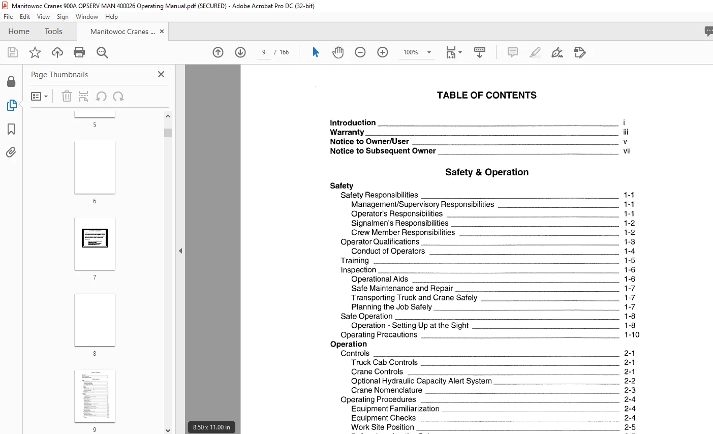
TABLE OF CONTENTS:
Manitowoc Grove Crane Series 900A Articulating & Telescoping Operating Manual – PDF DOWNLOAD
Introduction _ _
Warranty iii
Notice to Owner/User v
Notice to Subsequent Owner vii
Safety & Operation
Safety
Safety Responsibilities 1-1
Management/Supervisory Responsibilities 1-1
Operator’s Responsibilities 1-1
Signalmen’s Responsibilities 1-2
Crew Member Responsibilities 1-2
Operator Qualifications 1-3
Conduct of Operators 1-4
Training 1-5
Inspection 1-6
Operational Aids 1-6
Safe Maintenance and Repair 1-7
Transporting Truck and Crane Safely 1-7
Planning the Job Safely 1-7
Safe Operation 1-8
Operation – Setting Up at the Sight 1-8
Operating Precautions 1-1 O
Operation
Controls _ 2-1
Truck Cab Controls 2-1
Crane Controls 2-1
Optional Hydraulic Capacity Alert System _ 2-2
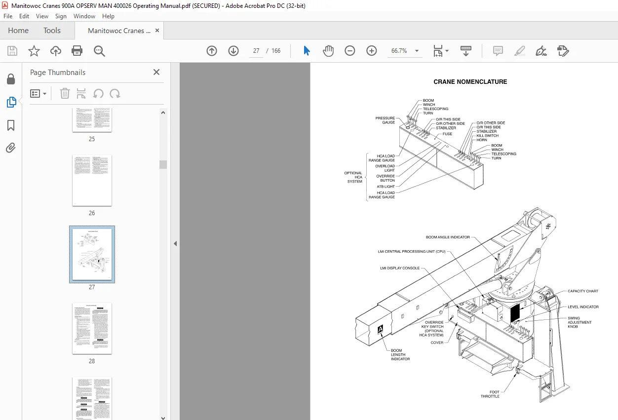
Crane Nomenclature _ 2-3
Operating Procedures 2-4
Equipment Familiarization 2-4
Equipment Checks 2-4
Work Site Position 2-5
Before Leaving the Cab 2-5
Crane Set Up 2-5
Before Making the Lift 2-6
Reading and Understanding the Capacity Chart 2-7
Winch System Operation 2-12
Using Multiple Part Lines 2-12
General Rules when Operating the Winch 2-12
Lifting the Load 2-12
Shutting Down and Preparing for Road Travel 2-13
Optional Winch Burst of Speed Operation 2-13
Anti-Two-Block System 2-14
Description/Operation 2-14
Optional Hydraulic Capacity Alert System 2-15
System Description 2-15
System Operation 2-15
Jib Safety and Operation 2-17
Safety Tips for Jib Operation 2-18
Side Folding – Swing Around Jib Operation 2-18
Jib Maintenance 2-19
Jib Jack 2-20
Operation 2-20
IX
Adjustable Swing Speed Valve _ 2-21
Standard Hand Signals for Controlling Crane Operations 2-22
Optional Hydraulic Capacity Alert System _ 2-23
Trouble Shooting _ 2-24
Maintenance & Repair 2-25
Maintenance, Lubrication & Service
Maintenance
Inspection and Maintenance 3-1
Inspection _ 3-1
Daily Inspections _ 3-1
Weekly Inspections 3-1
Monthly Inspections 3-2
Periodic Inspections _ 3-2
Other 3-2
Wire Rope Inspection and Maintenance 3-3
Inspection _ 3-3
Rope Replacement 3-3
Care of the Wire Rope 3-4
Rope Construction 3-4
Adjustments and Repairs 3-4
Tire Load and Inflation Table 3-5
Lubrication
Lubrication Procedures and Charts 4-1
Lubricants 4-1
Hydraulic Oil 4-1
Lubrication Points 4-2
Wire Rope Lubrication 4-2
Lubrication Chart 4-3
Hydraulic Oil Reservoir Level 4-4
Service
Service and Repair _ 5-1
Cleanliness 5-1
Hydraulic Systems 5-1
Fasteners & Torque Values 5-1
Label Parts When Disassembling 5-2
Welding Precautions 5-2
National Crane Fitting O’Ring Part Numbers 5-2
Torque Values for Grade 5 and 8 Bolts 5-3
Using Torque Wrench Extensions 5-4
Winch Oil Level 5-5
Brake Oil Level 5-5
Trouble Diagnosis 5-6
Hydraulic Schematic 5-9
Electrical Schematic 5-11
Electrical Schematic with ATB Reel 5-13
Electrical Schematic OS 160 LMI System 5-15
LM I Electrical Schematic DS 150C LM I System 5-17
Anti-Two Block Trouble Diagnosis – Electrical 5-19
Anti-Two Block Trouble Diagnosis – Hydraulic 5-21
Cylinder Disassembly and Repair 6-1
Single-Stage Extend Cylinder Disassembly and Repair 6-2
Cylinder Diassembly 6-2
Cylinder Reassembly 6-2
Four Section Boom Operation 6-3
Boom Illustrations 6-4
Four Section Boom Maintenance 6-5
X
Internal Cable Sheave Lubrication 6-5
Four Section Cable Tensioning 6-5
Four Section Boom Service _ 6-7
Boom Removal 6-7
Boom Disassembly 6-7
Additional Maintenance/Disassembled Boom 6-8
Four Section Boom Assembly 6-9
Four Section Top/Bottom Pad Replacement, Assembled Boom 6-12
Top Rear Pad Replacement 6-12
Front Bottom Pad Replacement 6-12
Three Section Boom Operation 6-13
Boom Illustrations 6-14
Three Section Boom Maintenance 6-15
Internal Cable Sheave Lubrication 6-15
Three Section Cable Tensioning 6-15
Three Section Boom Service 6-16
Boom Removal 6-16
Boom Disassembly 6-16
Additional Maintenance/Disassembled Boom 6-17
Three Section Boom Assembly 6-18
Three Section Top/Bottom Pad Replacement, Assembled Boom 6-20
Top Rear Pad Replacement 6-20
Front Bottom Pad Replacement 6-20
Inner Wear Pad Calibration 7-1
Inner side Pads 7-1
Inner Boom Pad Lubrication 7-3
Jib Installation and Adjustment 7-4
Jib Jack Service and Maintenance 7-7
Adding Oil 7-7
Changing Oil 7-7
Lubrication 7 -7
Rust Prevention 7-7
Trouble Shooting 7-7
(Optional) Oil Cooler Service and Maintenance 7-8
Rotation Gearbox and Brake Illustration 7-9
Swing Drive Service 7-1 o
Lubrication and Maintenance 7-1 o
Oil Capacities 7 -1 O
Disassembly Procedure 7-1 O
Assembly Procedure 7-11
Servicing the Control Valves 7-12
Disassembly and Reassembly of Control Valves to Replace Seals 7-12
Replacing Spool Seals 7-12
Control Valve Relief Adjustment 7-13
Unloader Dump Valve -Air Purging Instructions 7-14
Hydraulic System Description 7-15
Service Manual for Pump
Service Manual for Load Moment Indicator
Specifications
Dimensional Specification 8-1
Dimensional Specification Tractor Mount 8-2
Specifications 8-3
Capacity Chart 8-5
XI
Installation
Installation _ 9-1
Typical Locations/Serial Number Identification _ 9-2
Minimum Truck Requirements 9-3
Mounting Configurations 9-4
Configuration 1 – 9103A 9-5
Configuration 2 – 9103A _ 9-5
Configuration 3 – 990A/969A 9-6
Configuration 4 – 990A/969A 9-6
Configuration 5 – Rear Mount 9-7
Contiguration 6 – 9103A New York City Approved 9-7
Configuration 7 – 9103A New York City Approved 9-8
PTO Horsepower Requirements 9-9
Direct Mount Pump to PTO 9-9
Pump Rotation 9-9
Auger System 9-9
PTO Selection 9-1 o
Truck Frame Strength 9-11
Section Modulus Tables 9-12
Truck Frame and Mounting Bolt Requirements for Front Stabilizer 9-15
Section Modulus Tables 9-16
Truck Preparation 9-19
Welding Precautions 9-19
Positioning Crane on Truck 9-19
PTO, Pump, Reservoir 9-19
Reinforcing/After Frame Extension 9-20
After Frame Modification 9-23
Crane Installation 10-1
Pin Bearing Inspection and Installation Procedure 10-5
Pin Inspection 10-5
Bearing Inspection 10-5
Trunnion Inspection 10-5
Installation 10-5
Counterweighting 10-6
Counterweighting New York City Approved 10-7
Counterweighting Methods for Stability Around the Rear 180° 10-1 o
Anti-Two-Block Load Moment Indicator Installation and Function Verification 10-12
Initial Crane Run-In Procedure 10-14
Boom Rests 10-15
Stability Check 10-16
Stability Check New York City Approved 10-17
Questions? Email us: [email protected]
S.M