Manitowoc Grove Crane TMS 700 Series Superstructure Operator Manual PDF
$27.95
Description
Manitowoc Grove Crane TMS 700 Series Superstructure Operator & Service Handbook Manual – PDF DOWNLOAD
FILE DETAILS:
Manitowoc Grove Crane TMS 700 Series Superstructure Operator & Service Handbook Manual – PDF DOWNLOAD
Language : English
Pages : 148
Downloadable : Yes
File Type : PDF
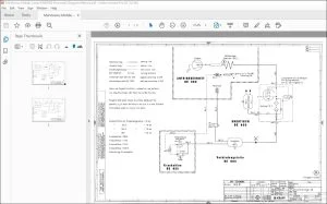
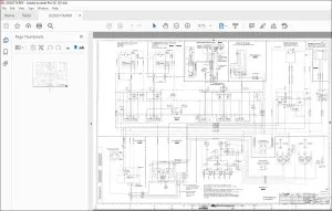
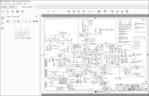
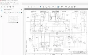
IMAGES PREVIEW OF THE MANUAL:
TABLE OF CONTENTS:
Manitowoc Grove Crane TMS 700 Series Superstructure Operator & Service Handbook Manual – PDF DOWNLOAD
Section 1 – INTRODUCTION 1-1
Section 2 – SAFETY PRECAUTIONS H 2-1
GENERAL 2-1
CRANING OPERATION 2-6
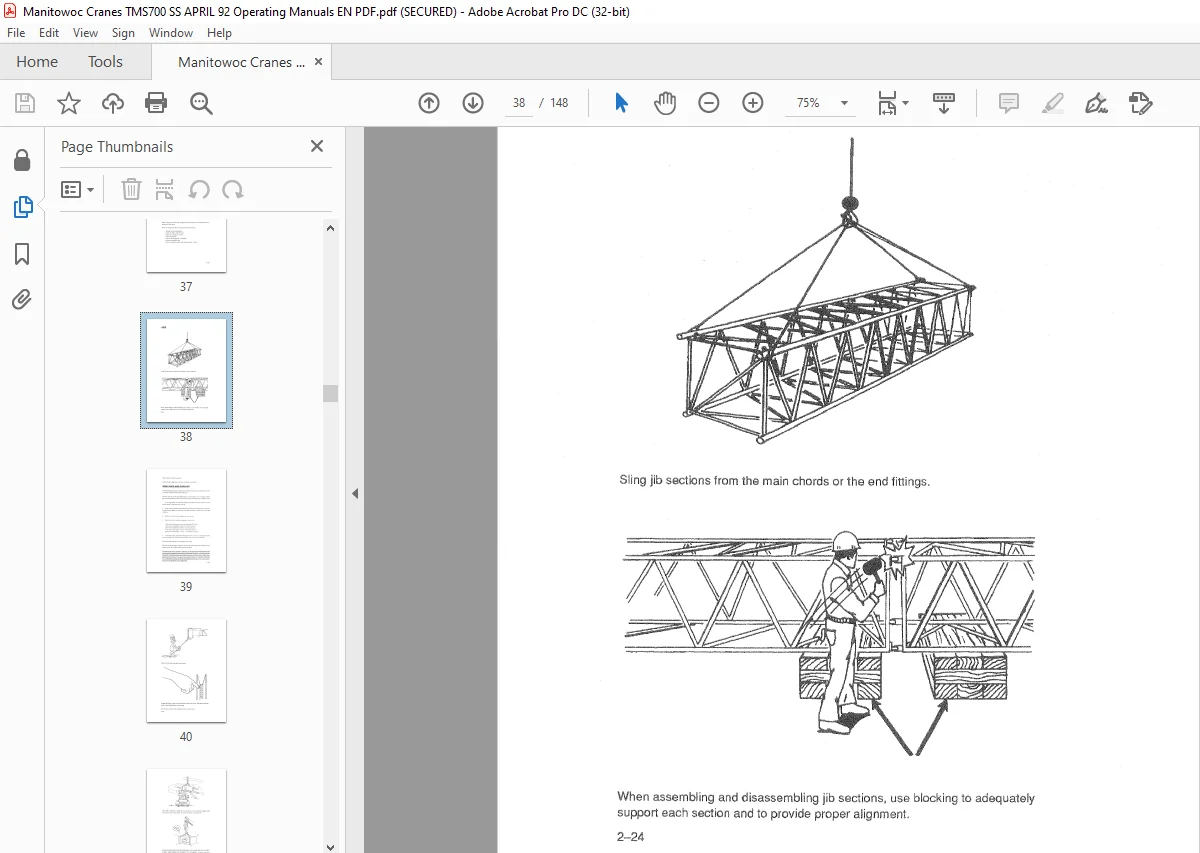
JIBS 2-24
WIRE ROPE AND SHEAVES 2-25
CONTROLLED FREE-FALL HOIST 2–30
ELECTRICAL HAZARDS 2-30
PERSONNEL PLATFORMS 2–42
COLD WEATHER OPERATION 2-42
DON’T FORGET 2-43
Section 3 – CAB CONTROLS AND INDICATORS 3-1
GENERAL 3-1
ENGINE CONTROLS AND INDICATORS 3-1
High Water Temperature/Low Oil Pressure Indicator 3-1
Water Temperature Gauge 3-1
Engine Of! Pressure Gauge 3-7
Tachometer 3-7
Voltmeter 3-7
Ignition On Indicator 3-7
Fuel Quantity Gauge 3–7
Foot Throttle Pedal 3–7
Th rattle Lock Contra I 3-8
Ignition Switch 3-8
CRANING CONTROLS AND INDICATORS 3-8
Front Stabilizer Overload Indicator 3-8
Swing Control Lever and Pedal 3-8
Swing Horn Button 3-8
Outer-Mid Telescope Control Lever 3-9
Inner-Mid Telescope Control Lever 3-9
Swing Brake Pedal 3-9
Boom Elevation Control Lever and Pedal 3-9
Hoist Rotation Indicator 3-9
Auxillary Hoist Control Lever 3-9
Main Hoist Control Lever 3-9
Boom Latch Pin Control Switch 3-10
Boom Latch Pin Engaged Indicator 3-1 0
Boom Latch Pin Disengaged Indicator 3-10
Outer-Mid Fully Extended Indicator 3-10
Outrigger Control Panel 3-·10
Swing Brake Controt Valve 3-1 O
Bubble Level Indicator 3–11
vii
LE F TE TS (continued}
Page
Positive Swing lock Control Handle 3-11
Third Wrap Indicator 3-11
Main Hoist Speed Selector Switch 3-11
Auxiliary Hoist Speed Selector Switch 3-11
ACCESSORY CONTROLS AND INDICATORS 3-11
Cab Circulating Fan 3-11
Instrument lights Switch 3-11
Windshield Wiper/Washer Switch 3-12
Panel Light and Switch 3-12
Boom light Switch 3-12
Beacon Light Switch 3-12
Defroster Control 3-12
Heater Temperature Control 3-12
Heater Control Panel 3-12
Fire Extinguisher 3-12
Dome Light 3-12
Spotlight and Switch 3-13
Electric Skylight Wiper Control 3-13
Section 4 – OPERATING PROCEDURES 4-1
PRE-STARTING CHECKS 4-1
Fuel Supply 4-1
Engine Oil 4-1
Engine Coolant 4-1
Batteries 4-1
Hydraulic Oil Reservoir and Filter 4-1
Daily Lubrication 4-1
Wire Rope 4-1
Hook Block 4-2
Swingaway Extension 4-2
Air Cleaner 4-2
Counterweight 4-2
Trailing Boom 4-2
ENGINE OPERATION 4-3
Starting Procedure 4-3
Cold Weather Starting 4-4
Idling the Engine 4-4
Racing the Engine 4-5
Shutdown Procedure 4-5
GENERAL CRANE OPERATION 4-5
Handling the Load 4-5
Control Lever Operation 4-7
Preload Check 4-7
viii
LE F TE T {continued}
Page
USING YOUR LOAD CHART 4-8
CRANE FUNCTIONS 4-9
Setting the Outriggers 4–10
Stowing the Outriggers 4–11
Setting the Center Front Stabilizer 4-13
Stowing the Center Front Stabilizer 4-13
Telescoping the Boom (Full Power Boom Operation 4-14
Extending the Boom 4-14
Retracting the Boom 4-15
Remote Power Latching Boom Operation 4-15
Extending the Fly Section 4-16
Retracting the Fly Section 4-18
Swinging the Boom 4-19
Elevating and Lowering the Boom 4–~20
Elevating the Boom 4–20
Lowering the Boom 4-21
Boom Lift (Foot) Control 4-21
Emergency Boom Operating Procedures 4-21
Hoisting Up and Down 4-22
Hoisting Down 4-22
Hoisting Up 4-23
Hoist Speed Range Selection 4-23
Stowing and Parking after the Working Day 4-23
Section 5 -OPERATIONAL AIDS 5–1
GENERAL 5-1
LOAD MOMENT INDICATING (LMI) SYSTEM 5-1
CONTROL LEVER LOCKOUT 5–1
ANTITWO–BLOCK SYSTEM 5-2
Section 6 – LUBRICATION 6-1
GENERAL 6-1
LUBRICATION POINTS 6-1
WIRE ROPE LUBRICATION 6-16
Section 7 – SET UP AND INSTALLATION PROCEDURES 7-1
GENERAL 7-·1
Installing Cable on the Hoist 7-1
CABLE REEVING 7–2
DEAD-END RIGGING/WEDGE SOCKETS 7-2
Installing the Wedge and Socket 7–3
ERECTING AND STOWING THE SWINGAWAY
BOOM EXTENSION 7-6
Erecting 7-6
Stowing 7-13
ix
TA L F (continued}
Page
Setting the Offset 7-15
Setting the Telescoping Extension Length 7-18
Extending 7-18
Retracting 7-19
COUNTERWEIGHT REMOVAL AND INSTALLATION 7-19
Removal 7-19
Installation 7-21
TRAILING BOOM 7-26
Operating Mode to the Trailing Mode 7-26
Trailing Mode to the Operating Mode 7-28
Questions? Email us: [email protected]
S.V