Manitowoc Grove Yardboss 4208 / 4408 Crane Operator Manual PDF
$26.95
The Manitowoc Grove Crane Yardboss 4208 / 4408 Operator’s & Safety Handbook Manual in PDF is crucial for safe operation. Download for detailed instructions and reference.
Description
Manitowoc Grove Crane Yardboss 4208 / 4408 Operator’s & Safety Handbook Manual – PDF DOWNLOAD
FILE DETAILS:
Manitowoc Grove Crane Yardboss 4208 / 4408 Operator’s & Safety Handbook Manual – PDF DOWNLOAD
Language : English
Pages : 120
Downloadable : Yes
File Type : PDF
IMAGES PREVIEW OF THE MANUAL:
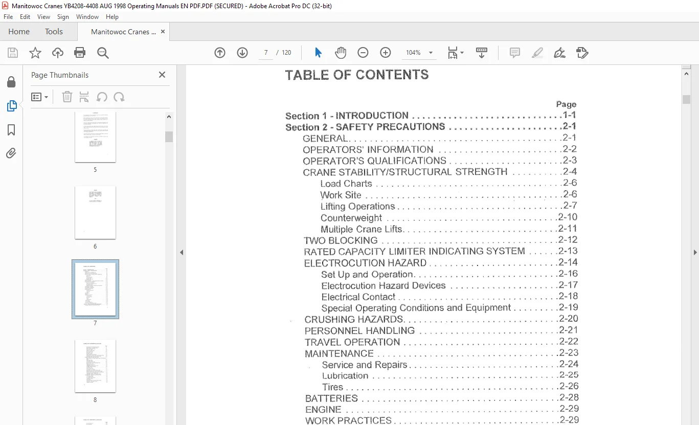
TABLE OF CONTENTS:
Manitowoc Grove Crane Yardboss 4208 / 4408 Operator’s & Safety Handbook Manual – PDF DOWNLOAD
Section 1 ~ INTRoouc·noN 1-1
Section 2 – SAFETY PRECAUTIONS 2-1
GEt- JER AL 2–1
OPERATORS’ INFOHMATION 2-2
OPERATOR’S QUALIFICATIONS 2-3
CRANE STABILITY/STRUCTURAL STRENGTH 2A
Load Charts 2 6
Work Site 2–6
Lifting Operations : 2-7
Counterweight 2-10
Multiple Crane Lifts 2~·11
TWO BLOCKING 2-·12
HATED CAPACITY LIMITER INDICATING SYSTEM 2-13
ELECTROCUTION HAZARD 2–14
Set Up and Operation 2-16
Electrocution Hazard Devices 2-17
Electrical Contact 2-’18
Special Operating Conditions and Equipment 2-19
CRUSHING HAZARDS 2–20
PERSONNEL HANDLING 2–2·1
TRAVEL OPERATION 2-22
MAINTENANCE 2-23
S i d R ?-24 erv ce an epairs L
Lubrication 2-25
Tires 2-26
BATTERIES 2-28
ENGINE 2–29
WORK PRACTICES 2-29
Crane Access 2-29
Job Preparation 2-30
Working 2-31
Lifing 2-32
Hand Signals 2–34
TRAVELING 2-35
SHUT DOWN 2-36
BOOM EXTENSION 2-31
COLD WEATHER OPERATION 2-39
Section 3 – CAB CONTROLS AND INDICATORS 3-1
ENGINE CONTROLS AND INDICATORS C 3-1
vii
TABLE OF CONTENTS (continued)
Page
Transmission Oil Temperature Gauge 3-1
Engine Water Temperature Gauge 3-1
Engine Oil Pressure Gauge 3-1
Fuel Level Gauge 3-4
Ignition and Start Switch 3-4
Foot Throttle Pedal 3-4
Hourmeter Gauge 3–4
Voltmeter Gauge 3-4
Engine Distress Indicator Light 3-4
Cold Start Push Button Switch (Diesel Engine Only) 3-5
Fuel Select Switch (Dual-Fuel Engine Only) :3-5
CRANE CONTROLS AND INDICATORS _ – 3-3
Rear Wheels Not Centered Indicator Light (4 Wheel Steer
Only) 3-5
Foot Brake Pedal 3-5
Park Brake Switch 3-5
Transmission Shift Lever 3-6
Steer Control Lever (4 Wheel Steer Only) – 3-6
Swing Control Lever 3-6
Telescope Control Lever 3-6
Outrigger/Tow Winch Control Lever 3-6
Outrigger Selector Switches 3-6
Lift Control Lever 3-7
Hoist Control Lever 3-7
Park Brake On Indicator 3-7
90% Rated Load Capacity Warning Light 3-7
Maximum Rated Load Capacity Lock Out Light 3-7
Anti-Two Block Indicator Light with Warning Buzzer 3–7
Operating Condition Selector Knob 3-8
Operating Condition On/Off Bypass Switch 3-8
ACCESSORY CONTROLS AND INDICATORS 3-8
Horn Button Switch _ 3-8
Turn Signai Switch 3-8
Four-Way Flasher Switch 3–8
Headlights Switch 3-9
Dome Light 3-9
Windshielcl Wiper and Washer Wiper Switch 3-9
Heater Air Temperature Control 3-9
Heater Fan Switch – 3-9
viii
TABLE OF CONTENTS (continued)
Page
Cab Circulating Fan 3-10
Fire Extinguisher 3- 10
Spotlight (Not Shown) 3-10
Flasher Light (Not Shown) 3-10
Work Lights Switch 3-10
Section 4 M OPERATING PROCEDURES 4-1
PRE-STARTING CHECKS 4-1
Fuel Supply 4-1
Engine Oil 4-1
Engine Coolant 4-1
Batteries 4-1
Signal Working and Marker Lights 4-2
Foot and Parking Brakes 4-2
Daily Lubrication 4-2
Hydraulic Reservoir and Filter 4-2
Tires 4-2
Wire Rope 4-2
Hook Block 4-2
Air Cleaner 4-3
ENGINE OPERATION 4-3
Starting Procedure 4-3
Cold-Weather Starting 4-4
Diesel Engine 4-4
Dual-Fuel Engine 4-5
Idling the Engine 4 5
Racing the Engine 4-5
Shutdown Procedure 4-6
Gasoline/LP Engine 4-6
Diesel Engine 4–6
Dual-Fuel Operation 4-7
Gasoline to LP Gas A-7
LP Gas to Gasoline 4-7
CRANE TRAVEL OPERATION 4-7
Traveling – General 4-7
Moving the Crane 4-9
Steering 4-9
Traveling – Forward (Automatic Transmission) 4-1 0
Traveling – Reverse (Automatic Transmission) 4-10
GENERAL CRANE OPERATION 4-10
ix
TABLE OF CONTENTS (continued)
Page
Control Lever Operation 4-1 O
Preload Check 4-11
USING YOUR LOAD CHART 4-12
CRANE FUNCTIONS 4-13
Setting the Outriggers 4-14
Stowing the Outriggers 4-14
Swinging the Boom 4-14
Elevating and Lowering the Boom 4-15
Elevating the Boom 4-15
Lowering the Boom 4-15
Telescoping the Boom 4-17
Extending the Boom 4-17
Retracting the Boom 4-18
Lowering and Raising the Cable 4M18
Lowering the Cable 4-18
Raising the Cable 4-19
Recommended Crane Shutdown Procedures 4-19
OPTIONAL EQUIPMENT OPERATION 4-20
Hot Water Heater/Defroster 4-20
Operating 4-20
Section 5 – LUBRICATION 5-1
GENERAL 5-1
LUBRICATION POINTS 5-2
WIRE ROPE LUBRICATION 5-11
Section 6 – SET UP AND INSTALLATION PROCEDURES 6-1
GENERAL 6~1
INSTALLING CABLE ON THE HOIST 6-1
CABLE REEVING 6-2
DEAD-END RIGGING/WEDGE SOCKETS 6-2
Installing Wedge and Socket 6-4
ERECTING AND STOWING THE SWINGAWAY
BOOM EXTENSION 6-7
Erecting 6~ 7
Stowing 6-10
SEARCHER HOOK 6-11
General 6-11
Installation 6-11
Removal 6-11
Section 7 ~ OPERATIONAL AIDS 7-1
X
TABLE OF CONTENTS (continued)
Page
RATED LOAD CAPACITY LIMITER SYSTEM 7-1
Central Processing Unit 7-1
9 1M (30 FT) Boom 7-2
7 3 M (24 FT) Boom 7-3
TROUBLESHOOTING 7-4
ROUTINE MAINTENANCE AND INSPECTION 7-5
ANTI-TWO BLOCK SYSTEM 7-5
Need help? Contact: [email protected]
https://vimeo.com/909976040?share=copy
S.V