Manitowoc Grove Cranes TM9150 Series Carrier Operator’s Manual PDF
$19.95
Description
Manitowoc Grove Cranes TM9150 Series Carrier Operator’s Manual – PDF DOWNLOAD
FILE DETAILS:
Manitowoc Grove Cranes TM9150 Series Carrier Operator’s Manual – PDF DOWNLOAD
Language : English
Pages : 94
Downloadable : Yes
File Type : PDF
IMAGES PREVIEW OF THE MANUAL:
TABLE OF CONTENTS:
Manitowoc Grove Cranes TM9150 Series Carrier Operator’s Manual – PDF DOWNLOAD
Section 1 – INTRODUCTION 1-1
Section 2 – SAFETY PRECAUTIONS 2-1
GENERAL 2-1
OPERATOR’S INFORMATION 2-2
OPERATOR’S QUALIFICATION 2-3
ELECTROCUTION HAZARD 2-4
Set-Up and Operation 2-5
Electrocution Hazard Devices 2-6
Electrical Contact 2-8
Special Operating Conditions and Equipment 2-8
CRUSHING HAZARDS 2-9
TRAVEL OPERATION 2-11
MAINTENANCE 2-12
Service and Repairs 2-13
Lubrication 2-13
Tires 2-14
BATTERIES 2-14
ENGINE 2-15
WORK PRACTICES 2-15
Crane Access 2-15
Job Preparation 2-15
COLD WEATHER OPERATION 2-16
Section 3-CAB CONTROLS AND INDICATORS 3-1
ENGINE CONTROLS AND INDICATORS 3-1
Voltmeter 3-1
Ignition Switch 3-1
Oil Pressure Gauge 3-1
Tachometer/Hourmeter 3-2
Engine Temperature Gauge 3-2
Fuel Quantity Gauge 3-2
Foot Throttle Pedal 3-2
Engine Brake Switch 3-2
Engine Brake Select Switch 3-2
Engine Stop Light 3-2
Idle/Diagnostic Switch 3-6
Test Mode Switch 3-6
Fluid/Warning Light 3-6
TRAVEL CONTROLS AND INDICATORS 3-6
Speedometer 3-6
Air Pressure Gauge 3-(>
Parking Brake Control 3-6
Suspension Pressure Gauges 3-7
Suspension Locked Indicator 3-7
Suspension Power Switch 3-7
Suspension Power Indicator 3-7
Ride Height Control Switch 3-7
Ride Heightlndicator 3-7
Ride Height Up-Down Control Switch 3-8
Park Brake Indicator 3-8
Transmission Shift Lever 3-8
Range Control Button 3-8
Clutch Pedal 3-8
Brake Pedal 3-8
Low Air Pressure Indicator 3-8
Auxiliary Transmission Control 3-9
Auxiliary Transmission Low Range Indicator 3-9
Transmission High Temperature Indicator 3-9
Inter-Axle 0ttferential lock Control 3-9
Differential Locked Indicator 3-9
Emergency Steer Indicator 3-10
Swing Brake On Indicator 3-1 O
Trailer Emergency Brake Control 3-10
Auxiliary Transmission Temperature Gauge 3-10
Transmission Temperature Gauge 3-1 o
Center Front Stabilizer Down Indicator 3-1 O
ACCESSORY CONTROLS AND INDICATORS 3-10
Cab Circulating Fan 3-1 O
Horn Button 3-11
Turn Signal Lever 3-11
Left Turn Signal Indicator 3-11
Right Turn Signal Indicator 3-11
Four-Way Flasher Switch 3-11
Flasher Light 3-11
Cab Dome Light (Not Shown) 3-11
Fire Extinguisher 3-11
Windshield Wiper Switch 3-12
Headlights Switch 3-12
Headlight High Beam Indicator 3-12
Beacon Light Switch 3–12
Heater Control Switch 3-12
Temperature Control 3-12
Defrost Control 3-12
Dimmer Switch 3-13
Tire Inflation Switch 3-13
Tire Inflation Indicator 3-13
ADDITIONAL CARRIER CONTROLS 3-13
Outrigger Control Box 3-13
Outrigger Selector Switches 3-13
Outrigger Extension/Retraction Switch 3-14
Center Front Stabilizer Switch 3-14
Bubble Level Indicator 3-14
Outrigger Pin Control Box 3-14
Engage/Disengage Switch 3-14
Power Switch 3-14
Section 4 – OPERATING PROCEDURES 4-1
BREAKING IN A NEW CARRIER 4-1
PRE-STARTING CHECKS 4-1
Fuel Supply 4-1
Engine Oil 4-2
Engine Coolant 4-2
Batteries 4-2
Seats 4-2
Seat Belts 4-2
Seat Belt Maintenance 4-2
Cleaning Seat Belt Webbing 4-2
Signal and Running Lights 4-2
Foot and Parking Brakes 4-2
Tires 4-3
Wheels 4-3
Safety Equipment 4-3
Daily Lubrication 4-3
COLD WEATHER OPERATION 4-3
ENGINE OPERATION 4-3
Starting Procedure 4-4
Cold Weather Starting 4-5
Idling the Engine 4-5
Racing the Engine 4-6
Shutdown Procedure 4-6
CRANE TRAVEL OPERATION 4-6
Active Restraints 4-6
Seat Belts 4-6
Traveling – General 4-7
Clutch Operation 4-8
Shifting Gears 4-9
Shifting Sequence 4-11
Upshifting 4-12
Downshifting 4-13
Driving Tips 4-13
Auxiliary Transmission 4-14
Inter-Axle Differential 4-14
Brakes 4-14
Recommended Crane Shutdown Procedures 4-16
GENERAL OPERA TING LIMITATIONS 4-17
Traveling/Preparing for Travel 4-17
Setting Up to Lift 4-18
Lifting 4-19
Counterweight/Aux Hoist Mounting and Removal 4-19
OPTIONAL EQUIPMENT OPERATION 4-20
Engine Brake 4-20
Engine Block Heater 4-20
Section 5 – LUBRICATION 5-1
GENERAL 5-1
LUBRICATION POINTS 5-1
WIRE ROPE LUBRICATION 5-23
LIST OF FIGURES
Title Page
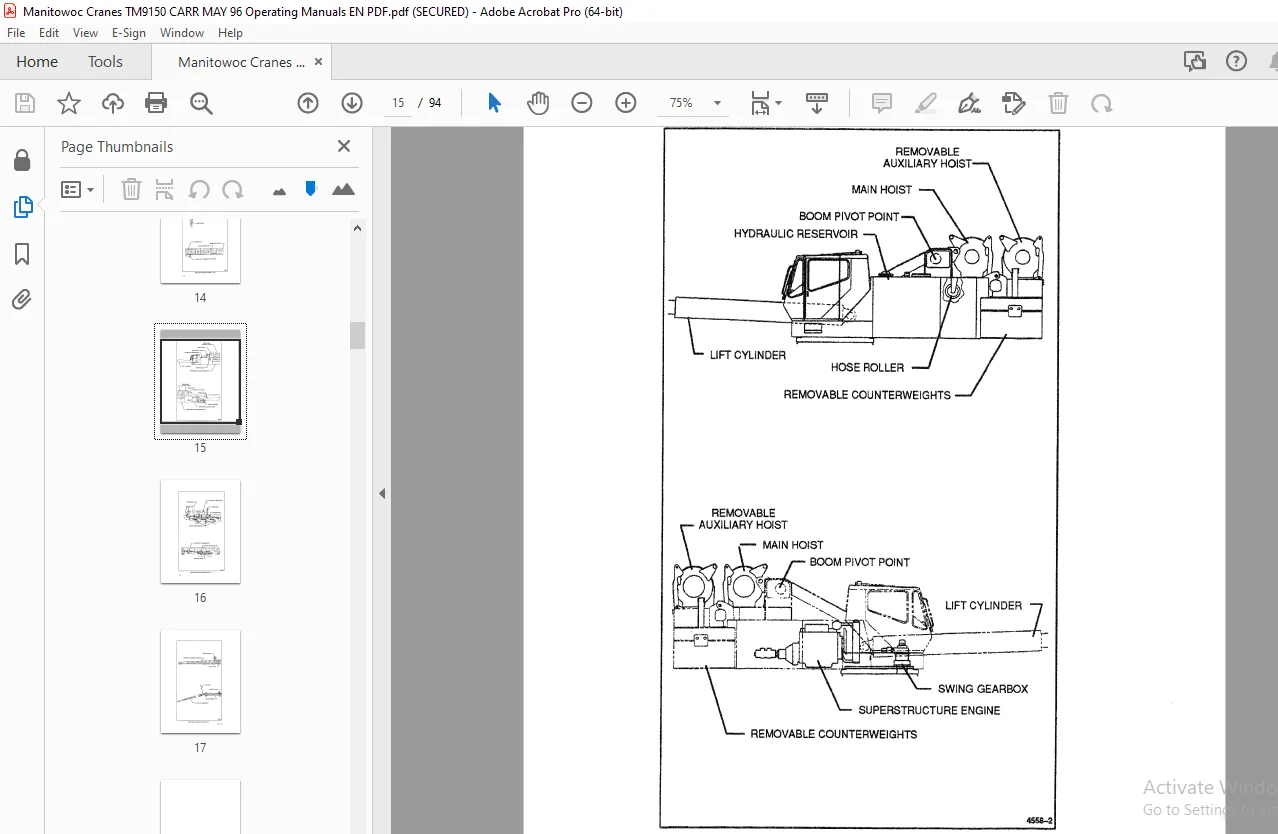
Basic Nomenclature 1-2
Cab Controls and Indicators 3-3
Additional Carrier Controls 3-15
Clutch Travel 4-8
Shift Pattern· 4-11
Lubrication Chart 5-4
S.S