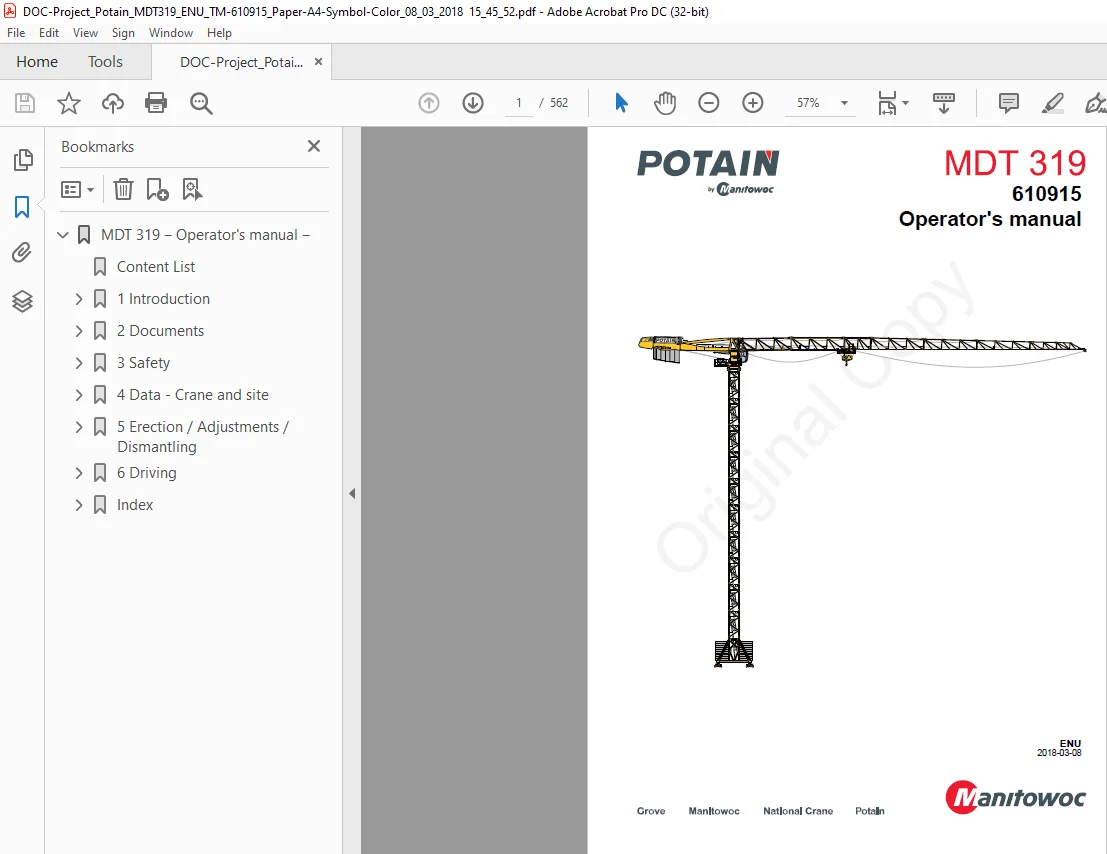

Manitowoc Potain Crane MDT 319 Operator’s Manual 610915 – PDF DOWNLOAD
$30.95
Description
Manitowoc Potain Crane MDT 319 Operator’s Manual 610915 – PDF DOWNLOAD
FILE DETAILS:
Manitowoc Potain Crane MDT 319 Operator’s Manual 610915 – PDF DOWNLOAD
Language : English
Pages : 562
Downloadable : Yes
File Type : PDF
IMAGES PREVIEW OF THE MANUAL:
TABLE OF CONTENTS:
Manitowoc Potain Crane MDT 319 Operator’s Manual 610915 – PDF DOWNLOAD
MDT 319 ‒ Operator’s manual ‒ 1
Content List 3
1 Introduction 15
1 1 Introduction 15
1 1 1 Development of the technical instructions 16
1 1 2 Other useful information sources 16
1 1 3 Contact details 17
1 2 Graphic symbols 17
1 3 Conventions 19
1 3 1 Typography of the paragraphs 19
1 3 2 Lists 19
1 3 3 References 19
1 4 Topless MDT terminology 20
2 Documents 21
2 1 Foreword – Documents part 21
2 2 Manufacturer plate 21
2 3 Sound pressure 21
2 4 Initial erection report 22
2 5 First Commissioning Report 24
2 6 New crane product warranty 33
2 6 1 Structural warranty items 35
2 6 2 Guarantee claims 35
2 7 Network Manitowoc Crane Care 35
2 8 Training center 35
3 Safety 37
3 1 Foreword – Safety section 37
3 2 Safety warnings 38
3 3 Weather conditions 39
3 3 1 Wind 39
3 3 2 Temperature 41
3 3 3 Humidity/rainfall 42
3 3 4 Natural disasters 42
3 4 Special installations 43
3 5 Crane supports 43
3 6 Ground 43
3 7 Environmental conditions 43
3 7 1 Atmosphere with the presence of chemically active substances 43
3 7 2 Explosive atmosphere 43
3 7 3 Electromagnetic field 43
3 7 4 Radiation 44
3 8 Conditions relating to the design of the crane 44
3 8 1 Suitability of the crane for the operating site 44
3 8 2 Crane power supply 44
3 8 3 Vibrations produced by the crane 44
3 8 4 Crane driver work station 45
3 8 5 Safety devices 45
3 8 6 Load indicator 45
3 8 7 Protection devices 45
3 8 8 Service life 45
3 8 9 Duty cycle of mechanisms 46
3 8 10 Weathervaning 47
3 8 11 Customer advertising plates 47
3 8 12 Fire extinguisher 47
3 8 13 Modifications to the crane/welding 47
3 8 14 Adaptation of equipment/replacement of parts 47
3 8 15 Monitoring of the crane/checks 48
3 8 16 Disposal 48
3 9 Installation conditions of the crane 48
3 9 1 Distance between cranes and fixed obstacles 48
3 9 2 Distance between crane and aerial line 49
3 9 3 Safety distance for the track ends 49
3 9 4 Daytime lighting 49
3 10 Handling conditions 49
3 10 1 Handling equipment 49
3 10 2 Handling of loads 50
3 10 3 Handling with two cranes 50
3 10 4 Lifting personnel 50
3 10 5 Ballasting derricks 50
3 10 6 Servicing derricks 50
3 11 Safety signs 51
3 11 1 Explanation 51
3 11 2 Terminology 51
3 11 3 Signs 52
Warning signs 52
Prohibition sign 53
3 11 4 Sound and light signals 53
Sound signals 53
Light signals 54
Associated sound and light signals 54
3 12 Safety controls 54
3 13 General safety instructions 55
3 13 1 General – General safety instructions 55
3 13 2 Instructions for users 55
3 13 3 Instructions for operating conditions 57
3 13 4 Instructions for specific hazards 58
3 13 5 Safety Instructions for the preparation of each operational phase 59
4 Data – Crane and site 61
4 1 Foreword – Data – Crane and site 61
4 2 Load curves 61
4 2 1 Foreword – Load curves 61
Description of a load curve table 62
Example of reading a load curve table 62
4 2 2 Load curves – MDT 319 – 1C/2C 64
4 3 Space requirements and masses 66
4 3 1 Slewing crane part 66
Diagram 66
Space requirements and mass of the elements of the slewing crane part 66
Space requirement of the slewing crane part 72
Mass of equipped jibs 76
4 3 2 Crane tower K600 77
Diagram 77
Space requirements and mass of mast sections 77
4 3 3 Crane base K600 80
Diagram 80
Dimensions and mass of fixing angles P62B 81
Dimensions and mass of fixing angles P61B 82
Dimensions and mass of reusable fixing angles R62B 83
Dimensions and mass of chassis V60A1 83
Dimensions and mass of chassis V63A1 85
Dimensions and mass of cross-shaped base ZD463 88
Dimensions and mass of cross-shaped base ZX6830 91
4 4 Mast composition, base ballast and reactions 93
4 4 1 Foreword – Mast composition, base ballast and reactions 93
Symbols used 94
4 4 2 Mast composition and base ballast 94
Explanation of the mast composition and base ballast tables 95
Height reduction due to the telescopic cage 95
Adjusting the hook height based on the trolley type 96
Definition and general rules for substitution of K-type masts 96
Equivalents for K600 masts 97
Information relating to fixing angles P61B, P62B and R62B 97
Information relating to the V60A chassis 98
Information relating to the V63A chassis 98
Information relating to the cross-shaped base ZD463 98
Information relating to the cross-shaped base ZX6830 99
4 4 3 Explanation of the reaction tables 99
4 4 4 Explanation of the tables of stresses above the concrete blocks 101
In-service calculations 103
Out-of-service calculations 103
Data during erection 104
4 4 5 Explanation of the tables of pressures under the concrete blocks 104
4 4 6 Mast composition, base ballast and reactions 105
4 5 Auxiliary lifting equipment 105
4 5 1 Foreword – Auxiliary lifting equipment 105
Hook height of the auxiliary lifting equipment 106
4 5 2 Erection of the crane using only auxiliary lifting equipment 107
4 5 3 Erection of the crane by telescoping 108
Fitting the telescopic cage using the auxiliary lifting equipment 108
Fitting the telescopic cage using the crane 109
4 6 Identification of the slewing crane part 110
4 6 1 Foreword – Identification of the slewing part 110
4 6 2 Identification of the towerhead/cab mast assembly 110
4 6 3 Identification of the counter-jib 111
4 6 4 Identification of the jib 111
Identification of the jib sections 111
Composition of the jibs 111
4 6 5 Identification of the 2C trolley 112
4 6 6 Identification and position of wind-sail plates 113
Function of the wind-sail plates 113
Identification of the wind-sail plates 113
Position of the wind-sail plates 113
4 6 7 Customer advertising plates 115
Fitting possibilities 115
Positions and dimensions of the customer advertising plate fixing flats 116
4 7 Identification and technical characteristics of the wire ropes 116
4 7 1 Trolley ropes 116
Technical characteristics 117
4 7 2 Hoist rope 118
Hoist rope for very high cranes 118
Hoist rope length 119
Technical characteristics 119
4 7 3 Jib guard rope 120
4 8 Technical characteristics of the hook 121
4 8 1 Diagram 121
4 8 2 Data sheet – Hook 122
4 9 Composition of the counter-jib ballast 122
4 9 1 Foreword to the composition of the counter-jib ballast 122
4 9 2 Type and mass of counter-jib ballast blocks used 123
4 9 3 Partial ballasting 124
4 9 4 Final ballasting 125
4 10 Rules for preparing the reinforced concrete elements 128
4 10 1 Concrete 128
4 10 2 Steel 129
4 11 Preparing the counter-jib ballast blocks 129
4 11 1 Foreword to preparing the counter-jib ballast blocks 129
Information about the mass 130
4 11 2 Preparing the CBS block 130
Layout plan 130
Parts list of reinforcements 132
Reinforcement layout 134
Detailed views 135
4 11 3 Preparing the CBU block 135
Layout plan 135
Parts list of reinforcements 137
Reinforcement layout 139
Detailed views 140
4 11 4 Preparing the CBY block 140
Layout plan 140
Parts list of reinforcements 142
Reinforcement layout 144
Detailed views 145
4 12 Fitting reusable fixing angles R62B 146
4 12 1 Fitting fixing rods 146
4 12 2 Determination of the fitting of the fixing angles 147
Calculation of the fitting of the fixing angles 147
Calculation of the capacity of a fixing rod (corresponding to the elastic limit) 147
Determining the number of fixing rods 148
Calculation of the prestress 149
4 13 Preparing concrete blocks for fixing angles P61B / P62B / R62B 149
4 13 1 Foreword to preparing the concrete blocks 149
4 13 2 Preparing the concrete block M81N 150
Designation and basic data 150
Fitting of reinforcements and dimensions of the concrete block 150
Table of reinforcements 151
4 13 3 Preparing the concrete block M101N 151
Designation and basic data 151
Fitting of reinforcements and dimensions of the concrete block 152
Table of reinforcements 152
4 13 4 Preparing the concrete block M126N 153
Designation and basic data 153
Fitting of reinforcements and dimensions of the concrete block 153
Table of reinforcements 154
4 13 5 Preparing the concrete block M142N 154
Designation and basic data 154
Fitting of reinforcements and dimensions of the concrete block 155
Table of reinforcements 155
4 13 6 Preparing the concrete block M169N 156
Designation and basic data 156
Fitting of reinforcements and dimensions of the concrete block 156
Table of reinforcements 157
4 13 7 Preparing the concrete block M205N 157
Designation and basic data 157
Fitting of reinforcements and dimensions of the concrete block 158
Table of reinforcements 158
4 13 8 Preparing the concrete block M278N 159
Designation and basic data 159
Fitting of reinforcements and dimensions of the concrete block 159
Table of reinforcements 160
4 14 Installation on traveling gear 160
4 14 1 Preparing the track 160
Selection criteria 160
Selecting the rails to use 161
Laying the track 161
4 14 2 Width of the tracks 162
4 14 3 Curve radii of the tracks 162
Curved track – with sliding bogies 163
Curved track – with non-sliding bogies 163
4 14 4 Track tolerance 164
Average track dimension 164
Rail position drawing 165
Rail level (slope) 165
Level of the rails in relation to each other (crosslevel) 165
Crosslevel of the rails in relation to each other 165
Position of the buffers in relation to each other 165
Crosslevel of the rail surface of the head compared to the horizontal 166
4 14 5 Track 166
4 14 6 Tracks on wooden sleepers 168
4 14 7 Tracks on longitudinal sleepers 169
Installing the longitudinal sleepers 169
Installing the longitudinal sleepers 171
Installing the longitudinal sleepers 173
Installing the longitudinal sleepers 175
Installing the longitudinal sleepers 177
Installing the longitudinal sleepers 179
Longitudinal sleeper assembly and connections 182
4 15 Installing stationary chassis V60A / V63A 185
4 15 1 Chassis on stools 185
4 15 2 Chassis installed on bed plate 187
4 16 Installing stationary cross-shaped base ZD463 188
4 16 1 Cross-shaped base on screw jacks / pyramidal support plates 188
4 16 2 Cross-shaped -base on screw jacks / concrete blocks 189
Preparing the concrete support block PC 190
4 17 Installing stationary cross-shaped base ZX6830 194
4 17 1 Cross-shaped base on screw jacks / pyramidal support plates 194
4 18 Preparing the base ballast blocks for chassis V60A / V63A 195
4 18 1 Foreword to preparing the base ballast blocks 195
4 18 2 Preparing block BC 195
Layout plan 196
Parts list of reinforcements 197
Reinforcement layout 198
4 19 Preparing the base ballast blocks for cross-shaped base ZD463 198
4 19 1 Foreword to preparing the base ballast blocks 198
4 19 2 Preparing block BA 199
Layout plan 199
Parts list of reinforcements 200
Reinforcement layout 201
4 19 3 Preparing block BD 201
Layout plan 201
Parts list of reinforcements 203
Reinforcement layout 204
4 20 Preparing the base ballast blocks for cross-shaped base ZX6830 205
4 20 1 Foreword to preparing the base ballast blocks 205
4 20 2 Preparing the BX block 205
Layout plan 206
Parts list of reinforcements 207
Reinforcement layout 208
4 20 3 Preparing the BY block 208
Layout plan 208
Parts list of reinforcements 209
Reinforcement layout 211
4 21 Balancing for telescoping 212
4 21 1 Principle of balancing for telescoping 212
Wind 213
4 21 2 Balancing parameters for telescoping 213
4 22 Balancing for climbing inside the building 214
4 22 1 Principle of balancing for climbing inside the building 214
Wind 215
4 22 2 Balancing parameters for climbing inside the building 215
4 23 Power supply 217
4 23 1 Regulations for electrical installations 217
4 23 2 Characteristics of the site power supply 217
4 23 3 Grounding 218
Different types of ground connections 219
Grounding a stationary crane 220
4 23 4 Characteristics of the crane power supply 220
Power 220
Power supply cable 221
Power supply from a generating set 221
Selecting an autotransformer 222
Calculation of a supply line 223
4 23 5 Definition of power and current intensity 228
Required power during operation 228
Required power during erection (GMA) 228
Nominal or rated current intensity 229
Starting current intensity 229
Crane power and current intensity values 229
4 23 6 Connecting the motors 229
Identification of the motors 230
Checking the direction of rotation of the motors 231
4 24 RFID tags 231
4 24 1 Overview of the RFID TAGS 231
Definitions 231
Information recorded by the manufacturer 232
Function 232
Replacement 233
4 24 2 Identification and location of the RFID TAGS 233
Definition of the elements equipped with a RFID TAG 234
5 Erection / Adjustments / Dismantling 237
5 1 Foreword – Erection 237
5 2 General mechanical rules 237
5 2 1 Standard tightening torques 237
5 2 2 Using split pins 238
5 2 3 Fitting the bulldog grips 239
5 2 4 Locking ropes using a rope anchor box 240
5 2 5 Using cable pulling grips 240
Overview 240
Cable pulling grip selection criteria 241
Procedure for attaching the cable pulling grip 242
Precautions for use 243
5 3 Fitting kinematics 244
5 3 1 Foreword – Erection kinematics 244
General fitting instructions 244
5 3 2 Fitting the base 246
5 3 3 Erecting the crane tower 247
5 3 4 Fitting the slewing crane part 248
5 3 5 Commissioning the crane 250
5 3 6 Erecting the crane tower by telescoping 251
5 3 7 Anchoring to the building 251
5 3 8 Climbing inside the building 252
5 4 Principle of fishplating 252
5 4 1 Characteristics of the fishplates on K-type masts 252
5 4 2 Fishplating 253
5 5 Tirax® 255
5 5 1 Description – Tirax 255
Block diagram – Tirax 256
5 5 2 Preparing the Tirax for use 256
5 5 3 Using the Tirax 257
5 6 Fitting fixing angles P62B 262
5 6 1 Possibilities of setting the fixing angles P62B 262
5 6 2 Setting the fixing angles in concrete with the fishplates using a template and a standard mast section 262
5 6 3 Setting the fixing angles in concrete with the fishplates using a template 266
5 6 4 Setting the fixing angles in concrete without the fishplates using a template 268
Fitting the fishplates on the fixing angles 269
5 7 Fitting reusable fixing angles R62B 271
5 8 Fitting fixing angles P61B 275
5 8 1 Possibilities of setting the fixing angles P61B 275
5 8 2 Setting the fixing angles in concrete with the fishplates using a template and a standard mast section 276
5 8 3 Setting the fixing angles in concrete with the fishplates using a template 279
5 8 4 Setting the fixing angles in concrete without the fishplates using a template 281
Fitting the fishplates on the fixing angles 283
5 9 Fitting the bogies 284
5 9 1 Checks before fitting bogies 284
5 9 2 Fitting the bogies for RT443 / RT544 traveling gear on straight track 285
5 9 3 Fitting the bogies for RT443 / RT544 traveling gear on curved track 286
5 9 4 Fitting the bogies for RT664 traveling gear on straight track 287
5 9 5 Lubricating the bogies (crane mounted on traveling gear) 288
5 10 Fitting base chassis V60A / V63A 288
5 10 1 Unloading and placing the basic mast section S41A1 / V60A1 / V63A1 288
5 10 2 Installing the chassis 292
Mounting chassis S41A / V60A / V63A on traveling gear 292
Mounting chassis S41A / V60A / V63A on stools 294
5 10 3 Ballasting of the chassis 296
Ballasting of the chassis S41A / V60A / V63A 296
Base ballast composition with BC blocks for chassis V60A 298
Base ballast composition with BC blocks for chassis V63A 298
Placing the ballast blocks: special case for the telescopic version 299
Additional ballasting by means of the crane in case of increase in height 300
Flanging the base ballast blocks 301
5 11 Fitting the cross-shaped base ZD463 302
5 11 1 Assembling the cross-shaped base ZD463 302
5 11 2 Installing the cross-shaped base 306
On traveling gear 306
Mounting on screw jacks / concrete blocks 306
Mounting on screw jacks / pyramidal support plates 308
Mounting on stools 311
5 11 3 Ballasting of the cross-shaped base 312
Ballasting of the cross-shaped base ZD463 with concrete blocks BA and BD 312
Base ballast composition with blocks BA and BD for cross-shaped base ZD463 317
5 11 4 Transport options 318
Transport with concrete block 318
Separating the elements of the cross-shaped base from the concrete blocks 318
5 12 Fitting the cross-shaped base ZX6830 319
5 12 1 Assembling the cross-shaped base ZX6830 319
5 12 2 Installing the cross-shaped base 324
Mounting on traveling gear 324
Mounting on screw jacks / pyramidal support plates 325
5 12 3 Ballasting of the cross-shaped base 328
Ballasting of the cross-shaped base ZX6830 with concrete blocks BX and BY 328
Base ballast composition with blocks BX and BY for cross-shaped base ZX6830 330
5 13 Erecting the crane tower (K64x2 and KR64x2 masts) 331
5 13 1 Preparing the K64x2 and KR64x2 masts 331
Mast panel identification 331
Recommended packaging 332
Tightening the fishplate bolts for assembling the mast panels 332
Assembling panel masts 334
Mast access identification 337
Fitting the platforms 337
Fitting the ladders on the platforms 339
Fixing ladders to mast diagonals 340
Fixing short ladders to removable supports 341
Fitting the towerhead access platform 342
5 13 2 Erecting the K64x2 and KR64x2 masts 343
Horizontal handling of mast sections 343
Raising masts 345
Vertical handling of mast sections 346
Fitting the basic mast section on the fixing angles 347
Fitting the basic mast section on the cross-shaped base 350
Fitting the basic mast section on the chassis 351
Fitting the remaining mast sections 353
5 14 Fitting of towerhead 354
5 14 1 Possibilities for fitting the towerhead 354
5 14 2 Fitting the towerhead gussets 356
5 14 3 Preparing the towerhead + platform assembly equipped with winches 50LVF or 75LVF 358
5 14 4 Fitting of towerhead and equipped winch platform assembly 360
Slinging parameters of the towerhead + equipped hoisting winch platform assembly 360
Fitting of the towerhead and equipped winch platform assembly 361
5 14 5 Preparing the cab mast 365
Fitting the access prohibiting set 370
5 14 6 Fitting the cab mast on the towerhead 371
Slinging of cab mast 371
Fitting the equipped cab mast on the towerhead assembly 373
5 14 7 Fitting the towerhead + cab mast assembly 376
Standard slinging parameters of the towerhead + cab mast 376
Fitting the handling yoke on the cab mast 377
Slinging parameters using the lifting device option 380
Fitting the towerhead + cab mast assembly 381
5 14 8 Putting the derrick into service 384
5 15 Fitting the K600 slewing collector 385
5 16 Preparing and fitting the counter-jib 391
5 16 1 Slinging the counter-jib 391
Slinging points on the counter-jib 391
Slinging parameters 391
5 16 2 Preparing the counter-jib 392
Dismantling the wind-sail plate assembly 397
Dismantling the wind-sail plates 398
5 16 3 Fitting the counter-jib 399
5 16 4 Fitting the anemometer 403
5 17 Fitting the counter-jib ballast blocks 403
5 18 Preparing the jib 406
5 18 1 Slinging principle of the jib sections 406
5 18 2 Checks required before assembling the jib sections 406
5 18 3 Equipping the jib foot 407
5 18 4 Assembling the jib sections 410
5 18 5 Fitting the jib nose 414
5 18 6 Fitting the wind-sail plates on the jib 415
5 18 7 Checking the presence of the guard rope on each jib section 416
5 18 8 Fitting the Load and Radius indicating plates 417
Description of the Load and Radius indicating plates 417
Fitting the Radius indicating plates 418
Fitting the Load indicating plates 419
5 19 Fitting the 2C trolleying equipment 419
5 19 1 Configuration options for the 2C trolley equipment 419
Fitting the trolley equipment in a 2C/four-fall configuration 420
Fitting the trolley equipment in a 2C/two-fall configuration 420
Fitting the 2C trolley equipment in a SM configuration 420
5 19 2 Fitting the inspection platform onto the trolley 421
5 19 3 Changing from 2C equipment to SM equipment 422
Modifying the trolley for a change from 2C configuration to SM configuration 422
Modifying the pulley blocks 423
5 19 4 Fitting the 2C trolleying equipment on the jib 424
Fitting the pulley block ballast 426
Carrying out the 2C temporary rope reeving 427
5 19 5 Fitting the SM trolleying equipment on the jib 429
Fitting the pulley block ballast 430
Carrying out the SM temporary rope reeving 432
5 20 Fitting the trolley ropes 433
5 20 1 Unwinding the wire rope 433
5 20 2 Fitting the rear trolley rope (2C trolley version) 433
5 20 3 Fitting the front trolley rope (2C trolley version) 435
5 20 4 Fitting the rear trolley rope (SM or SM/DM trolley version) 438
5 20 5 Fitting the front trolley rope (SM or SM/DM trolley version) 440
5 20 6 Tensioning the trolley ropes 443
5 20 7 Slackening the trolley ropes 444
5 20 8 Safety device against trolley rope breakage 445
Working principle 445
5 20 9 Checking the safety device 446
5 21 Fitting the jib 446
5 21 1 Slinging points on the jib 446
5 21 2 Standard jib slinging parameters 447
5 21 3 Slinging with yoke option 449
Description of the slinging yoke 449
Parameters for slinging the jib with a slinging yoke 450
5 21 4 Fitting the jib 452
5 22 Fitting the hoist rope (2C trolley version) 456
5 23 Fitting the hoist rope (SM trolley version) 459
5 24 Fitting the plates 464
5 24 1 Base plates 464
Identification and fitting position 464
Fitting the base plates (on aluminum ladders) 465
5 24 2 Height/load/radius indicating plate 466
Preparing the fixings of the height/load/radius indicating plate 466
Fitting the height/load/radius indicating plate on the mast 468
5 24 3 Slewing crane part plates and stickers 469
5 24 4 Telescoping equipment sticker 470
5 25 Erection mode 470
5 25 1 Before entering Erection mode 470
Powering off the crane 470
Connecting the plugs shunt 471
Powering on the crane 471
5 25 2 Before exiting Erection mode 472
Powering off the crane 472
Disconnecting the plugs shunt 472
Powering on the crane 473
5 26 Wind options – Anemometer and indicators 473
5 26 1 Foreword – Wind options – Anemometer and indicators 473
5 26 2 Diagram 474
5 26 3 Working principle 474
5 26 4 Connection 475
Connection – Repeater option 475
Connection – Repeater option with traveling box 476
Connection – Repeater option with Top Tracing 3 477
5 26 5 Display kit 478
5 27 Safety devices – General notes 479
5 27 1 Foreword – Safety devices 479
5 27 2 Block diagram – Active safety devices 479
5 27 3 Order of adjustment 480
5 28 Moment cutout 480
5 28 1 Block diagram 480
5 28 2 Working principle – Inductive moment sensors 481
5 28 3 Checking the inductive sensor air gap 481
5 28 4 Adjusting the air gap 483
5 28 5 Refitting the cover 485
5 29 Using telescoping equipment 486
5 30 Fitting the anchorage frames AK600 486
5 30 1 Foreword – Fitting the anchorage frames 486
5 30 2 Technical data of the anchorage frame AK600 487
Composition of a complete anchorage frame 487
Dimensions of the anchorage frame 488
5 30 3 Rules for fitting the anchorage frames AK600 on the mast sections 489
Fitting options for the anchorage frames on the crane tower 490
5 30 4 Installing the anchorage frames 491
Preparing the half frames on the ground 491
Adjusting the adjusting block 492
Fitting a frame on the crane tower 494
5 30 5 Loosening an anchorage frame 495
5 31 Using a floor climbing equipment 496
5 32 Dismantling kinematics 497
5 32 1 Foreword – Dismantling kinematics 497
General dismantling instructions 497
Preparation for dismantling 498
5 32 2 Telescoping down 498
5 32 3 Dismantling the slewing crane part 499
5 32 4 Dismantling the crane tower 503
5 32 5 Dismantling the base 503
5 33 Lubricant tables 503
6 Driving 513
6 1 Foreword – Driving 513
6 2 Prerequisite for driving a crane 513
6 3 Specific safety instructions concerning driving 513
6 4 Cab and control unit 514
6 4 1 Block diagram – Cab and control unit 514
6 4 2 Joysticks 515
6 4 3 Buttons and signal lamps 516
Control unit 516
Starting signal lamp 517
Control support 517
6 4 4 Unintended operations 518
Forward – Inopportune controls 518
Working principle – Inopportune controls 518
6 4 5 Standby function 519
Placing the crane in standby 519
Exiting crane standby 520
6 4 6 Slewing mechanism brake 520
6 4 7 Speed-limiting device 521
Increase the maximum speed 521
Reduce the maximum speed 522
6 4 8 Indicators on the CCS Display 522
Access to the Indicators screen 524
6 4 9 Using the air-conditioning/heating system 524
Air-conditioning unit – Heating 524
Using automatic mode 525
Using manual mode 526
Using the heating mode 526
Using the A/C air-conditioning mode 526
Demisting the cab 527
6 4 10 Seat adjustment 527
Adjustment of the seat spacing 527
Adjustment of seat inclination 528
Adjustment of seat inclination 528
6 5 Diagram – Locations of the emergency stop buttons 529
6 6 Reading the type plates 530
6 6 1 Block diagram – Type plate 530
6 6 2 Cab 530
6 6 3 Board 531
6 6 4 Example of reading the plates 531
6 7 Instructions when starting work 532
6 7 1 Block diagrams – Starting work 532
6 7 2 General instructions when starting work 532
6 7 3 Visual checks on the ground 533
6 7 4 Visual checks on the crane tower 534
6 7 5 Visual checks on the slewing crane part 534
6 7 6 Checks to perform at control unit in the cab 534
6 7 7 Checking the adjustment and functioning of the limit switches 536
6 8 Instructions during operating 538
6 9 Changing of 1C/2C rope reeving 544
6 9 1 Diagram – Changing rope reeving 544
6 9 2 Operating very high cranes 545
6 9 3 Changing from two-fall to four-fall rope reeving 546
6 9 4 Changing from four-fall to two-fall rope reeving 549
6 10 Instructions for shift 552
6 10 1 Diagrams – Shift 552
Crane without collector 552
Crane with collector 553
Crane with wired control box 553
Crane with flashing green weathervaning signal light 554
6 10 2 Instructions for the shift 554
Index 557
A 557
B 557
C 557
D 557
E 557
F 557
G 558
H 558
J 558
L 558
M 558
N 558
O 558
P 558
R 558
S 558
T 558
W 559
Need help? Contact: [email protected]
https://vimeo.com/906991513?share=copy
S.V