Maserati Spider M138 Workshop Manual & Wiring Digram Manual – PDF DOWNLOAD
Original price was: $94.00.$29.95Current price is: $29.95.
Maserati Spider M138 Workshop Manual & Wiring Digram Manual – PDF DOWNLOAD
Description
Maserati Spider M138 Workshop Manual & Wiring Digram Manual – PDF DOWNLOAD
The Maserati Spider M138 Workshop Manual & Wiring Diagram Manual is a comprehensive 742-page workshop and electrical reference manual for the Maserati M138 Spyder. It combines detailed mechanical service procedures with extensive electrical and wiring information, making it useful for servicing, repair, troubleshooting, component replacement and electrical diagnosis.
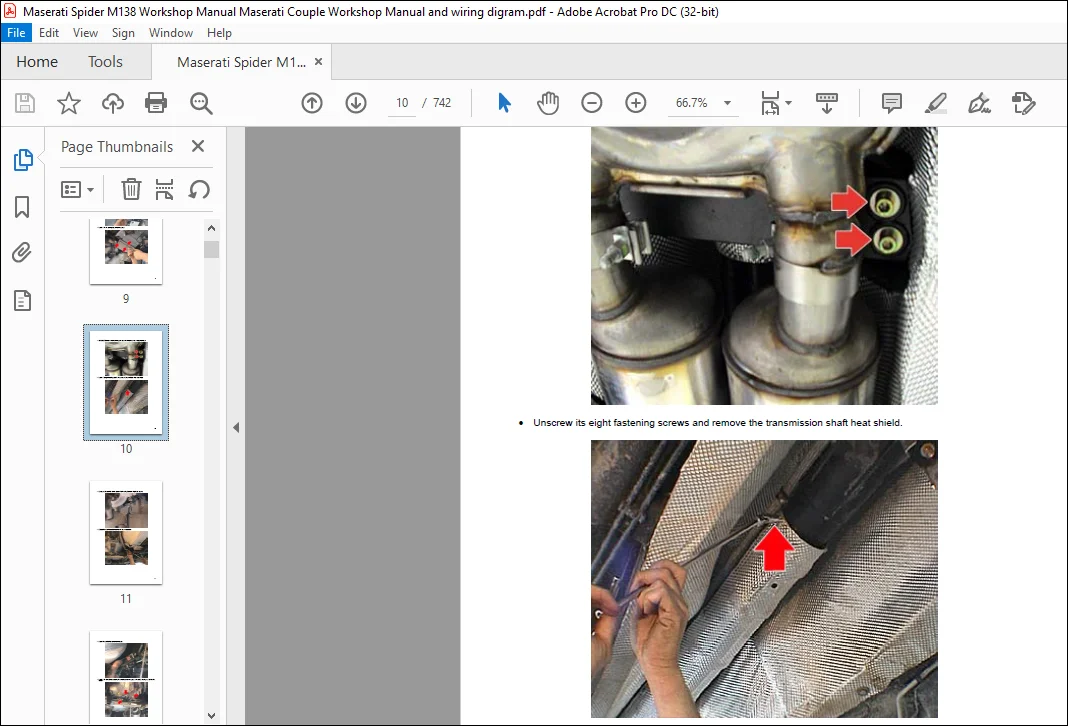
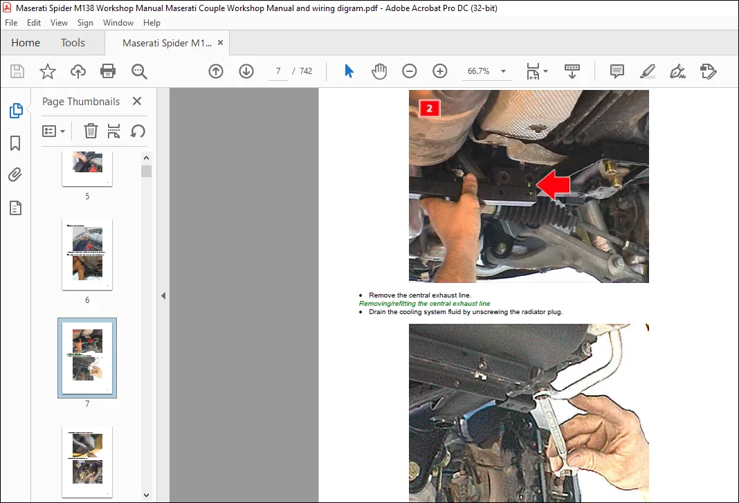
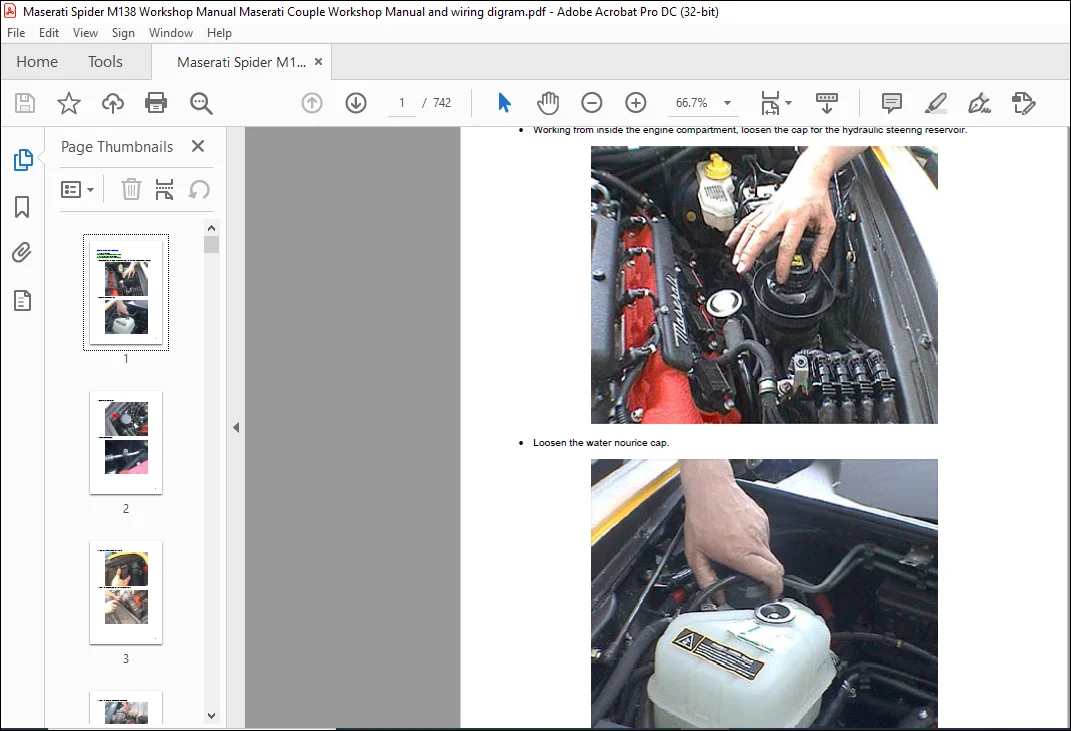
The workshop section provides detailed procedures covering engine removal and refitting, engine disassembly and timing, dimensional checks, fuel injection, cooling system, exhaust system, fuel system, clutch, differential, gearbox removal and overhaul, tightening torques and special workshop tools. Step-by-step instructions are supported throughout by photographs, diagrams, component illustrations and technical specifications.
A substantial section of the manual is dedicated to the Maserati Cambiocorsa electronically controlled gearbox, including gearbox removal and installation, TCU replacement, oil-level procedures, PIS adjustment, clutch removal and refitting, clutch balancing, bleeding, clutch sensor adjustment and gearbox control procedures.
M138 Spyder Electrical & Wiring Information
The electrical section provides detailed information specifically for the M138 Spyder, including earth locations, electrical components, control units, wiring harnesses, connector information and system wiring diagrams.
Electrical coverage includes:
- M138 Spyder main earth locations
- Fuel supply distribution
- Cambiocorsa robotized gearbox electrical system
- Engine fuel electronic management
- Electrical component identification
- Dashboard wiring
- Front door wiring
- Fuel tank cable bundle
- Injection wiring
- Passenger compartment wiring
- Luggage compartment wiring
- Robotized gearbox wiring
- Engine compartment wiring
- Dashboard branching ECU
- Engine Control Node (NCM)
- Robotized Gearbox Node (NCR)
- Luggage Compartment ECU
- Alarm and immobilizer system information
- Key programming and diagnostic procedures
The manual covers both mechanical gearbox and Cambiocorsa-related workshop information and includes M138 Spyder-specific details such as soft-top-area components, electrical earth locations and vehicle wiring. It is especially valuable when carrying out major mechanical repairs or tracing electrical, gearbox, injection and control-system faults.
This is a digital PDF manual in English containing 742 pages, allowing you to search, zoom and refer directly to the required workshop procedure or wiring section from your computer, tablet or other PDF-compatible device.
FILE DETAILS:
Maserati Spider M138 Workshop Manual & Wiring Digram Manual – PDF DOWNLOAD
Language : English
Pages : 742
Downloadable : Yes
File Type : PDF
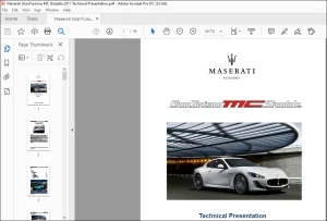
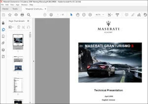
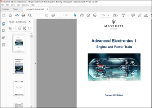
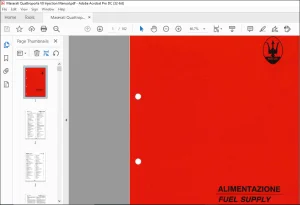
IMAGES PREVIEW OF THE MANUAL:
TABLE OF CONTENTS:
Maserati Spider M138 Workshop Manual & Wiring Digram Manual – PDF DOWNLOAD
WSM_M138_SPIDER...............................................................  1
	REMOVING-REFITTING THE ENGINE ............................................  1
	FILLING THE CIRCUITS AND CHECKING THE LEVELS ............................. 39
	RADIATORS ................................................................ 48
	OIL FILTER ............................................................... 62
	AIR FILTER ............................................................... 63
	CENTRAL EXHAUST LINE  .................................................... 67
	TAILPIPES ................................................................ 74
	ENGINE REMOVING .......................................................... 91
	FITTING AND TIMING THE ENGINE ............................................140
	 ADJUSTING THE INTAKE SHAFT TIMING  ......................................205
	 ADJUSTING THE EXHAUST SHAFT TIMING  .....................................207
	DIMENSIONAL CHECKS .......................................................234
	ELECTRO-INJECTORS ........................................................276
	BATTERY ..................................................................280
	STARTER MOTOR ............................................................283
	FUEL TANK ................................................................313
	MOTOR-DRIVEN PUMP PAN ASSEMBLY ...........................................329
	ANTI-EVAPORATION SYSTEM ..................................................345
	ACCELERATOR PEDAL REPLACEMENT ............................................352
	TIGHTENING TORQUES .......................................................356
	TOOLKIT ..................................................................359
	REMOVING-REFITTING THE ELECTRONICALLY-CONTROLLED GEARBOX .................361
	REPLACING THE ELECTRONICALLY-CONTROLLED GEARBOX CONTROL UNIT (TCU) .......366
	POWER UNIT REPLACEMENT ...................................................369
	ESTABLISHING THE ELECTRONICALLY-CONTROLLED GEARBOX OIL TANK LEVEL  .......375
	PIS ADJUSTMENT PROCEDURE .................................................377
	CLUTCH REMOVAL  ..........................................................381
	RE-ATTACHING THE CLUTCH  .................................................399
	CLUTCH BALANCING .........................................................415
	BLEEDING THE CLUTCH ......................................................437
	ADJUSTING THE CLUTCH PEDAL POSITION ......................................439
	CLUTCH PEDAL REPLACEMENT .................................................440
	CLUTCH PUMP  .............................................................444
	CLUTCH THRUST BEARING ....................................................452
	ADJUSTING THE CLUTCH SENSOR MAGNET .......................................460
	HALF SHAFTS ..............................................................465
	CROWN WHEEL – DIFFERENTIAL AND TAPERED ROLLER BEARINGS  ..................472
	GEARBOX REMOVAL ..........................................................482
	REFITTING THE DIFFERENTIAL -GEARBOX - ....................................528
	ADJUSTMENTS AND CHECKS ...................................................586
	GEARBOX CONTROL ADJUSTMENT  ..............................................640
	TIGHTENING TORQUES .......................................................643
	TOOLKIT ..................................................................645
	MECHANICAL GEARBOX LEVER HOUSING .........................................649
	MAIN EARTH LOCATION - M138 SPYDER ........................................656
	ALARM SYSTEM KIT REPLACEMENT .............................................665
	CHECK FOR CORRECT ALARM TRIGGER OPERATION  ...............................673
	IDENTIFICATION OF ALARM MEMORIES FOR THE METASYSTEM M826 ALARM SYSTEM ....674
	PROGRAMMING A NEW KEY ....................................................675
	DETACHING – REFITTING D-BOX  .............................................676
	DETACHING – REFITTING CLOTHES HOOK ON FRONT SEAT .........................677
	DETACHING – REFITTING ARMREST UNIT .......................................678
	DETACHING – REFITTING HANDBRAKE LEVER MY 04 ..............................683
	DETACHING – REFITTING FRONT AERIAL AMPLIFIER MY 04 .......................685
	DETACHING – REFITTING REAR AERIAL AMPLIFIER ..............................687
	YAW SENSOR ...............................................................689
	FUEL SUPPLY DISTRIBUTION .................................................691
	CAMBIOCORSA ROBOTIZED GEARBOX  ...........................................694
	ENGINES FUEL ELECTRONIC MANAGEMENT .......................................700
	ELECTRICAL COMPONENTS - DESCRIPTION ......................................711
	DASHBOARD WIRING .........................................................715
	FRONT DOOR WIRING DRIVER SIDE ............................................718
	FUEL TANK CABLE BUNDLE ...................................................719
	INJECTION WIRING .........................................................720
	PASSENGER COMPARTMENT WIRING .............................................721
	LUGGAGE COMPARTMENT WIRING ...............................................724
	ROBOTIZED GEARBOX WIRING .................................................725
	ENGINE COMPARTMENT WIRING ................................................726
	DASHBOARD BRANCHING ECU (CPL-B001) .......................................728
	ENGINE CONTROL NODE (NCM- M005) ..........................................731
	ROBOTIZED GEARBOX NODE (NCR-M018) ........................................737
	LUGGAGE COMPARTMENT ECU (CVB– M019) ......................................741
Need help? Contact: [email protected]
PLEASE NOTE:
- This is the SAME MANUAL used by the dealerships to diagnose your vehicle
- No waiting for couriers / posts as this is a PDF manual and you can download it within 2 minutes time once you make the payment.
- Your payment is all safe and the delivery of the manual is INSTANT – You will be taken to the DOWNLOAD PAGE.
- So have no hesitations whatsoever and write to us about any queries you may have : heydownloadss @gmail.com
S.V