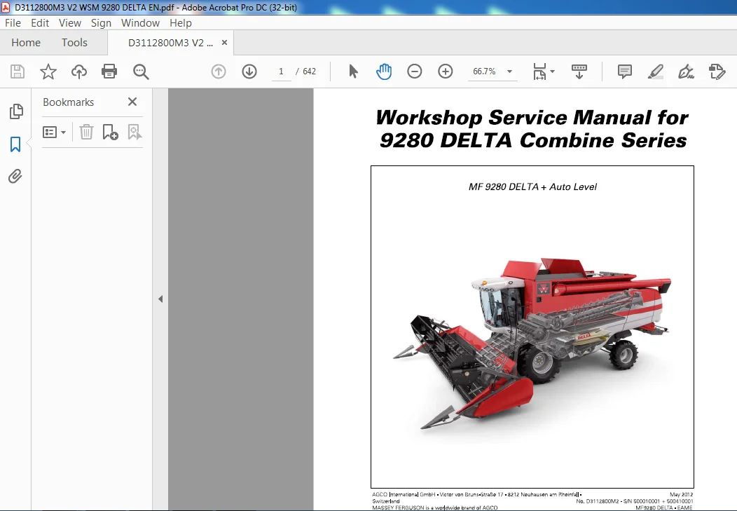
Massey Ferguson 9280 DELTA Combine Series Service Manual – PDF DOWNLOAD
Original price was: $85.95.$30.95Current price is: $30.95.
Massey Ferguson 9280 DELTA Combine Series Service Manual – PDF DOWNLOAD
Description
Massey Ferguson 9280 DELTA Combine Series Service Manual – PDF DOWNLOAD
DESCRIPTION:
Massey Ferguson 9280 DELTA Combine Series Service Manual – PDF DOWNLOAD
General
AII operations described in this manual relating to repairs and maintenance must only Ье carried out Ьу trained
service personnel. The purpose of the manual is to help dealers and workshops start up, service and repair
AGCO’s equipment as efficiently and effectively as possiЬle. lf the specified procedures аге followed and the
recommended special tools used where necessary, jobs сап Ье completed within the time indicated in the
“Repair Time Schedule” manual.
Use
То make it easier to look things up, there is а tаЫе of contents at the beginning of еvегу chapter listing the
various sections in the chapter.
Modifications
Modified pages have the same section numbering as their predecessors: Only the page number and version
number change.
The old pages must Ье destroyed.
Service tools
ln the case of jobs that require service tools, the number of the tool is specified at the point in the text where
it is needed.
Repairs and replacing parts
When replacing parts, it is vегу important to only ever use genuine AGCO spares.
Please рау particular attention to the following points when it comes to repairs and fitting spare parts ог other
equipment.
Fitting non-genuine spare parts may impair the safety of the machine.
ln some countries it is against the law to fit parts that do not conform to the manufacturer’s specifications.
Torque wrenches must always Ье adjusted in accordance with the instructions given in the workshop manual.
Fit locking devices where specified. lf the locking device breaks when removed, fit а new one.
lf non-genuine AGCO parts аге fitted, the machine will по longer Ье covered Ьу the right to complain, as the
manufacturer provides а warranty оп all AGCO components. AGCO dealers аге under the oЬligation to supply
genuine parts only.
Repair Time Schedule
The “Repair Time Schedule” manual contains а tаЫе of standard time requirements for the commonest repairs
оп а combine. The manual’s sections follow the layout of the spare parts catalogue.
TABLE OF CONTENTS:
Massey Ferguson 9280 DELTA Combine Series Service Manual – PDF DOWNLOAD
1 Introduction – Specifications 13
1 1 Using the manual 15
1 1 1 Using the manual 15
1 2 General specifications 16
1 2 1 General specifications 16
1 2 2 Tyre pressure 19
1 3 Dimensions and weight 21
1 3 1 Dimensions and weight 21
1 4 Safety precautions 23
1 4 1 Safety precautions 23
1 4 2 Safety in the workshop 23
1 4 3 Safety – a word to the mechanic 23
1 4 4 Safety- danger, warning and caution 23
1 4 5 Safety decals 24
1 4 6 General 24
1 4 7 Personal safety 24
1 4 8 Considerations with regard to equipment 25
1 4 9 General considerations 26
1 4 10 Operational considerations 26
1 4 11 Maintenance techniques 27
1 5 Practical advice 29
1 5 1 Practical advice 29
1 6 Start-up instructions 33
1 6 1 General 33
1 6 2 Pre-delivery checks 33
1 6 3 Instruction of combine operator 35
1 7 Conversion tables 38
1 7 1 Conventional units of measurement 38
1 8 Locking and sealing agents 39
1 8 1 Locking and sealing agents 39
1 9 Wheel nut torques 40
1 9 1 Wheels 40
1 9 2 Bolts with metric threads 40
1 9 3 Nuts with metric threads 41
2 Cutting table 43
2 1 General 45
2 1 1 Cutting table, general 45
2 2 Knife drive – wobble box 46
2 2 1 Removal 46
2 2 2 Assembly 46
2 2 3 Reconditioning the wobble box 47
2 2 4 Positioning the double fingers, knife and crop lifters 53
2 3 Table auger 54
2 3 1 Removal 54
2 3 2 Assembly 55
2 3 3 Replacing the shaft on the right-hand side 55
2 3 4 Replacing the shaft on the left-hand side 56
2 3 5 Replacing the crankshaft 57
2 3 6 Replacing the feathering fingers, bearings and bushes 58
2 3 7 Adjusting the table auger and feathering fingers 59
MF9280 DEL TA – EAME 3
D3112800M3
Table of contents MASSEY FERGUSON
2 4 Table body 60
2 4 1 Adjusting the cut-off strips 60
2 4 2 Adjusting and positioning the ground sensor – PowerFlow 61
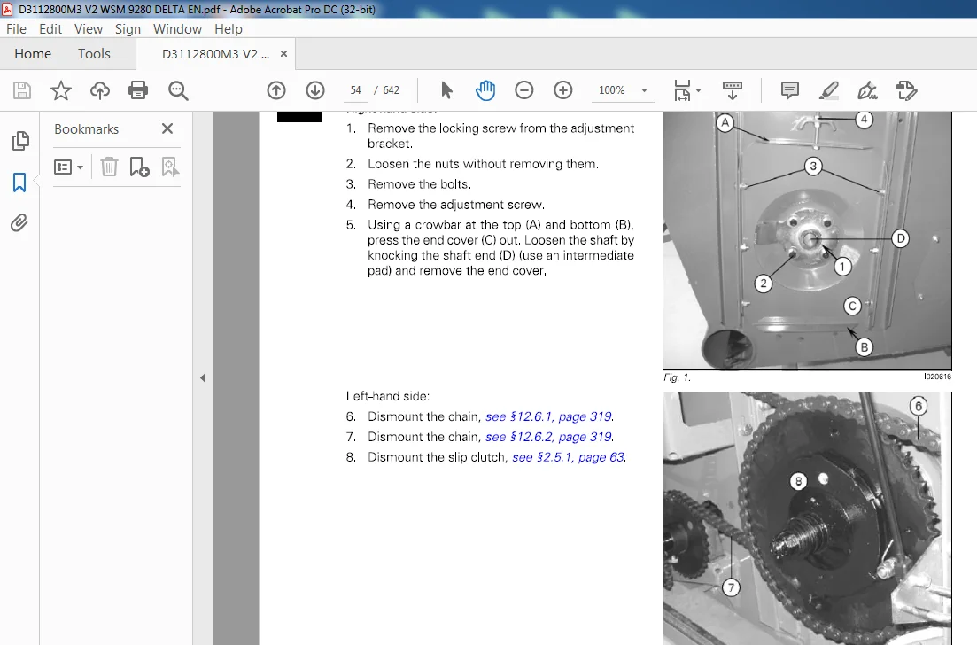
2 5 Slip clutch and chain drive 63
2 5 1 Removal 63
2 5 2 Assembly 63
2 5 3 Replacing the bearings and sprockets 64
2 6 Countershaft 65
2 6 1 Removal 65
2 6 2 Assembly 66
2 7 PowerFlow Table 67
2 7 1 PowerFlowTable 67
2 7 2 Removal, belts 67
2 7 3 Assembly, belts 70
2 7 4 Replacing the front rollers and bearings, scraper adjustment 71
2 7 5 Replacing the rear rollers and bearings, scraper adjustment 73
2 7 6 Replacing and aligning the bearing housing, rear rollers 74
2 7 7 Belt tensioning and running-in 75
3 Reel 79
3 1 Reel 81
3 1 1 Removal 81
3 1 2 Assembly 82
3 1 3 Replacing the reel tine bar and plastic bearings 83
3 1 4 Replacing the guide rollers, eccentric, guide ring and bearings 84
3 1 5 Replacing the reel plates 85
3 1 6 Replacing the reel tube, bearings 85
3 2 Oil motor and chain drive 86
3 2 1 Replacing the oil motor 86
3 2 2 Replacing the flow divider 86
3 3 Hydraulic cylinders 90
3 3 1 Replacing the cylinder – reel up/down 90
3 3 2 Replacement of cylinder – reel forward/back 91
3 3 3 Reconditioning of hydraulic cylinders 91
4 Main crop elevator 95
4 1 General 97
4 1 1 Main crop elevator, general 97
4 2 Main crop elevator 98
4 2 1 Removal 98
4 2 2 Assembly 99
4 2 3 Bearing block on machine frame 100
4 2 4 Replacement of lifting ram 100
4 2 5 Reconditioning of hydraulic cylinder 100
4 2 6 Replacing the cutting height preset sensor 101
4 3 Crop elevator chain 103
4 3 1 Crop elevator chain, general 103
4 3 2 Removal 103
4 3 3 Assembly 103
4 3 4 Replacement of slats 105
4 3 5 Replacing the slide rails in the crop elevator 105
4 3 6 Replacing the intermediate plate 106
4 4 Elevator chain top shaft 107
4 4 1 Removal 107
4 4 2 Assembly 108
4 4 3 Replacing the bearings 108
4 4 4 Replacing the sprockets 108
4 4 5 Replacing the shaft protection tube 110
4 5 Elevator chain front shaft 111
4 5 1 Removal 111
4 5 2 Assembly 111
4 5 3 Replacing the shaft, bearings and plate wheels 112
4 MF9280 DELTA -EAME
D3112800M3
MASSEY FERGUSON Table of contents
4 6 Elevator countershaft 113
4 6 1 Removal 113
4 6 2 Assembly 114
4 6 3 Replacing the bearings, belt pulley 114
4 7 Table clutch and belt drive 115
4 7 1 Removal 115
4 7 2 Assembly 115
4 7 3 Reconditioning the clutch 116
4 8 Adapter 117
4 8 1 Removal 117
4 8 2 Assembly 118
4 8 3 Replacing the cylinder/connecting rod 118
4 8 4 Reconditioning of hydraulic cylinder 118
4 8 5 Replacing the angle sensor 119
4 9 Hydraulic reversing 120
4 9 1 Removal 120
4 9 2 Assembly 120
5 Threshing unit 121
5 1 General 123
5 1 1 Threshing unit, general 123
5 2 Stone trap 124
5 2 1 Removal 124
5 2 2 Assembly 125
5 3 Concave 126
5 3 1 Removal 126
5 3 2 Assembly 127
5 3 3 Adjusting the concave laterally 127
5 3 4 Concave setting – initial setting 128
5 3 5 Replacing the actuator 129
5 3 6 Replacing the lead-in plate 130
5 3 7 Replacing the shaft for concave setting 130
5 4 Threshing cylinder 132
5 4 1 Removal 132
5 4 2 Assembly 133
5 4 3 Replacing the bearings 134
5 4 4 Replacing the rasp bars and backing bars 135
5 4 5 Replacing the shaft and cylinder spiders 135
5 5 Cylinder variator – table clutch 137
5 5 1 Removal, hydraulic variator 137
5 5 2 Assembly, hydraulic variator 138
5 5 3 Reconditioning the hydraulic variator pulley 138
5 5 4 Removal, mechanical variator 140
5 5 5 Assembly, mechanical variator 140
5 5 6 Reconditioning the mechanical variator pulley 141
5 5 7 Removal, magnetic clutch 142
5 5 8 Assembly, magnetic clutch 143
5 5 9 Reconditioning the magnetic clutch 144
5 6 Bracket for counter drive 147
5 6 1 Removal 147
5 6 2 Assembly and alignment 147
5 7 Rear beater 149
5 7 1 Removal 149
5 7 2 Assembly 150
5 7 3 Replacing the bearings 151
5 8 Rear beater concave 152
5 8 1 Removal 152
5 8 2 Assembly 152
5 9 Rotor Feeder 153
5 9 1 Removal 153
5 9 2 Assembly 154
5 9 3 Replacing the bearings 155
MF9280 DEL TA – EAME 5
D3112800M3
Table of contents MASSEY FERGUSON
5 9 4 Replacing deflector and distributor plates 156
5 10 Rotor Feeder concave 1 58
5 10 1 Removal 158
5 10 2 Assembly 158
6 Rotor unit 159
6 1 General 161
6 1 1 General 161
6 2 Rotor variator 162
6 2 1 Removal, hydraulic variator 162
6 2 2 Assembly, hydraulic variator 163
6 2 3 Reconditioning the hydraulic variator pulley 164
6 2 4 Removal, mechanical variator 164
6 2 5 Assembly, mechanical variator 164
6 2 6 Reconditioning the mechanical variator pulley – version 1 165
6 2 7 Reconditioning the mechanical variator pulley – version 2 166
6 2 8 Replacing and reconditioning the magnetic clutch 168
6 3 Shaft for mechanical varistor 170
6 3 1 Removal 170
6 3 2 Assembly 170
6 4 Right-angle gear 171
6 4 1 Removal 171
6 4 2 Assembly 172
6 5 Rotor 174
6 5 1 Removal 174
6 5 2 Assembly 175
6 5 3 Replacing the front bearing 176
6 5 4 Replacing the rear bearing 177
6 6 Rotor cage 178
6 6 1 Removal 178
6 6 2 Assembly 180
6 6 3 Replacing grate sections 180
7 Shaker shoe – Fanning mill 181
7 1 General 183
7 1 1 Shaker shoe – fanning mill, general 183
7 2 Fanning mill 184
7 2 1 Removal 184
7 2 2 Assembly 185
7 2 3 Replacing the fan blades 185
7 2 4 Replacing the fanning mill deflectors 186
7 2 5 Replacement of seals 187
7 3 Main grain pan frame 188
7 3 1 General 188
7 3 2 Removal 188
7 3 3 Assembly 189
7 3 4 Replacing the swivel arm and bearings 190
7 3 5 Replacing the seals 191
7 4 Second grain pan 192
7 4 1 Removal 192
7 4 2 Assembly 192
7 4 3 Replacing the swivel arm and bearings 193
7 4 4 Adjusting second grain pan 194
7 5 Top shaker shoe 196
7 5 1 Removal 196
7 5 2 Assembly 197
7 5 3 Replacing the swivel arm and bearings 198
7 5 4 Replacement of seals 199
7 5 5 Replacing and calibrating the actuator – sieves 199
7 6 Bottom shaker shoe 201
7 6 1 Removal 201
7 6 2 Assembly 202
6 MF9280 DELTA -EAME
D3112800M3
MASSEY FERGUSON Table of contents
7 6 3 Replacing the swivel arm and bearings 203
7 6 4 Replacing the seals 203
7 6 5 Electric sieve setting – initial setting 203
7 7 Bottom augers 204
7 7 1 Bottom augers 204
7 7 2 Removal 204
7 7 3 Assembly 205
7 8 Eccentric drive 206
7 8 1 Removal 206
7 8 2 Assembly 207
7 8 3 Adjusting the connecting rod/ aligning the shaker shoes 208
7 8 4 Replacing the connecting rod bearing 209
7 8 5 Replacing the bearings and eccentric shaft 210
7 9 Transmissions 211
7 9 1 Replacing and reconditioning the fanning mill variator 211
7 9 2 Adjusting the fanning mill variator 212
7 9 3 Replacing and reconditioning the counter drive 213
8 Elevators 215
8 1 Tank filling elevator 217
8 1 1 Removal 217
8 1 2 Assembly 218
8 1 3 Replacing the top shaft, bearings and sprockets 219
8 1 4 Replacement of bottom sprocket 220
8 1 5 Replacing the elevator chain 220
8 1 6 Moisture sensor 221
8 1 7 Yieldmeter sensor 221
8 2 Returns elevator 222
8 2 1 Removal 222
8 2 2 Assembly 223
8 2 3 Replacing the top shaft, bearings and sprockets 223
8 2 4 Replacing the bottom sprocket 224
8 2 5 Replacing the elevator chain 224
8 2 6 Returns volume sensor 224
8 3 Returns thresher 225
8 3 1 Removal 225
8 3 2 Fitting 225
8 3 3 Replacing the sprockets 225
8 3 4 Replacement of threshing cylinder 226
8 3 5 Reconditioning the right-angle gear 226
8 4 Tank filling auger 229
8 4 1 Removal 229
8 4 2 Fitting 229
8 4 3 Replacing the top bearing 229
8 4 4 Reconditioning the right-angle gear 230
8 5 Transmission 231
8 5 1 Replacing the shaft, bearings and sprockets 231
9 Engine 233
9 1 General 235
9 1 1 Engine, general 235
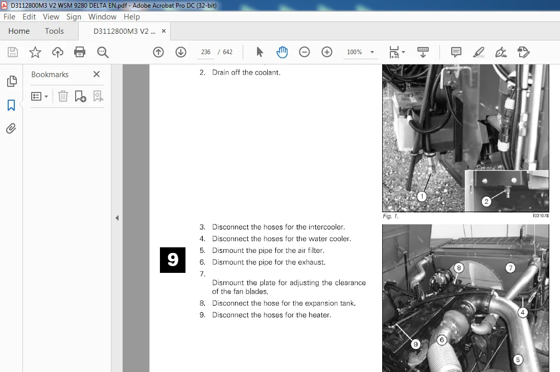
9 2 Replacing the engine 236
9 2 1 Removing the engine assembly 236
9 2 2 Fitting the engine assembly 238
10 Unloading auger – Grain tank 241
10 1 Unloading auger – horizontal 243
10 1 1 Removal 243
10 1 2 Assembly 243
10 2 Unloading auger – vertical 245
10 2 1 Removal 245
10 2 2 Assembly 245
MF9280 DEL TA – EAME 7
D3112800M3
Table of contents MASSEY FERGUSON
10 2 3 Reconditioning the right-angle gear 246
10 3 Unloading tube – horizontal 247
10 3 1 Removal 247
10 3 2 Assembly 247
10 4 Unloading tube – vertical 248
10 4 1 Removal 248
10 4 2 Assembly 248
10 4 3 Replacing the swivel bearing 249
10 4 4 Replacing the hydraulic cylinder 250
10 4 5 Reconditioning of hydraulic cylinder 250
10 5 Unloading tube elbow 251
10 5 1 Removal 251
10 5 2 Assembly 251
10 5 3 Reconditioning the right-angle gear 252
10 6 Bottom auger and cover plate 254
10 6 1 Removal 254
10 6 2 Fitting 255
10 6 3 Replacing the bearings, safety clutch 255
10 7 Transmission 257
10 7 1 Replacing the unloading auger shaft, bearings 257
10 7 2 Replacing and reconditioning the magnetic clutch 258
10 8 Grain tank covers 260
10 8 1 Removal 260
10 8 2 Assembly 261
11 Drive unit 263
11 1 Radiator – intercooler 265
11 1 1 Removal 265
11 1 2 Fitting 266
11 2 Oil cooler 267
11 2 1 Removal 267
11 2 2 Assembly 267
11 3 Fuel cooler 268
11 3 1 Removal 268
11 3 2 Assembly 268
11 4 Condenser – air conditioning 269
11 4 1 Removal 269
11 4 2 Assembly 269
11 5 Rotary screen 270
11 5 1 Removal 270
11 5 2 Assembly 271
11 5 3 Adjusting the rotary screen and cleaning blade 272
11 5 4 Replacing the drive shaft and clutch 273
11 6 Dust aspirator 276
11 6 1 Removal 276
11 6 2 Assembly 277
11 7 Hydrostatic pump 278
11 7 1 Removal 278
11 7 2 Assembly 280
11 8 Auxiliary hydraulic pump 281
11 8 1 Removal 281
11 8 2 Fitting 281
11 9 Hydraulic pump – Maxi Spreader 282
11 9 1 Removal 282
11 9 2 Assembly 282
11 10 Hydraulic oil tank 283
11 10 1 Removal 283
11 10 2 Fitting 283
11 11 Fuel tank 284
11 11 1 Removal 284
11 11 2 Fitting 284
11 11 3 Tank gauge 284
8 MF9280 DELTA -EAME
D3112800M3
MASSEY FERGUSON Table of contents
11 12 Diesel additive and dosing equipment 285
11 12 1 Removal 285
11 12 2 Assembly 285
11 12 3 Supply module 285
11 12 4 Dosing module 286
11 12 5 Tank sensor 286
11 13 Compressor – air conditioning 287
11 13 1 Removal 287
11 13 2 Assembly 287
11 14 Power take-off 288
11 14 1 Removal 288
11 14 2 Assembly 288
11 14 3 Replacing the clutch 289
11 14 4 Replacing the output shaft/bearings 290
12 Transmissions 291
12 1 General 293
12 1 1 Transmissions, General 293
12 2 Countershaft 294
12 2 1 Removal 294
12 2 2 Assembly 296
12 2 3 Replacing the bearings 296
12 2 4 Reconditioning the safety clutch 297
12 3 Replacing the belts, right-hand side 298
12 3 1 Rear beater – counter drive, cylinder variator 298
12 3 2 Counter drive, variator – threshing cylinder 299
12 3 3 Rear beater – Rotor Feeder 300
12 3 4 Fanning mill – fanning mill variator 300
12 3 5 Rear beater – fanning mill variator 301
12 3 6 Unloading auger shaft – unloading auger 301
12 3 7 Unloading auger shaft – rotary screen clutch 302
12 3 8 Unloading auger shaft – dust aspirator 303
12 3 9 Countershaft- counter drive, elevators 304
12 3 10 Rotor countershaft – right-angle gear 304
12 4 Replacing the chains, right-hand side 305
12 4 1 Counter drive, elevators – returns elevator 305
12 4 2 Counter drive, elevators – tank filling elevator 305
12 4 3 Counter drive, elevators – tank filling auger 306
12 4 4 Returns elevator – returns thresher 306
12 4 5 Reel drive 307
12 5 Replacing the belts, left-hand side 308
12 5 1 Countershaft – rear beater 308
12 5 2 Countershaft – counter drive, straw chopper 308
12 5 3 Counter drive – straw chopper 309
12 5 4 Engine – countershaft 309
12 5 5 Rear beater – countershaft, shaker shoe drive 311
12 5 6 Countershaft, shaker shoe drive – eccentric shaft 312
12 5 7 Engine – rotor countershaft 312
12 5 8 Rear beater – elevator chain top shaft/ front shaft 313
12 5 9 Engine – unloading auger shaft 315
12 5 10 Engine – hydrostatic pump 316
12 5 11 PTO shaft – table countershaft 317
12 5 12 Table countershaft – knife drive 317
12 5 13 Countershaft – hydraulic pump, chaff spreader 318
12 6 Replacing the chains, left-hand side 319
12 6 1 Table countershaft – table auger 319
12 6 2 Table auger – belt rollers (PowerFlow) 319
12 6 3 Hydraulic motor, reversing – elevator countershaft 320
12 6 4 Bottom auger – unloading auger 321
MF9280 DEL TA – EAME 9
D3112800M3
Table of contents MASSEY FERGUSON
13 Undercarriage 323
13 1 Auto Level final drive bracket 325
13 1 1 Removal 325
13 1 2 Assembly 326
13 1 3 Replacing the bushing 328
13 1 4 Replacing the hydraulic cylinder 329
13 1 5 Reconditioning of hydraulic cylinder 329
13 1 6 Adjusting the Auto Level potentiometer 330
13 2 Final drives 331
13 2 1 Removal 331
13 2 2 Assembly 332
13 2 3 Reconditioning the final drives 333
13 3 Gearbox 337
13 3 1 Removal 337
13 3 2 Assembly 338
13 3 3 Replacing the shifter cylinders and sensor 339
13 3 4 Adjusting the shifter cylinders and sensor 340
13 3 5 Replacing the lubrication pump 343
13 3 6 Replacing the shifter forks 344
13 3 7 Reconditioning the differential 345
13 3 8 Reconditioning the gearbox 348
13 4 Hydrostatic motor 352
13 4 1 Removal 352
13 4 2 Assembly 352
13 5 Brakes 353
13 5 1 Replacing the brake blocks 353
13 5 2 Replacement of brake discs 354
13 5 3 Bleeding the brakes 356
13 5 4 Brake pedals and main cylinder 356
13 5 5 Replacing the handbrake shoes 359
13 5 6 Adjustment of hydraulic hand brake 360
13 6 Rear axle 361
13 6 1 General 361
13 6 2 Removal 361
13 6 3 Assembly 362
13 6 4 Replacing the king pins and bushings 363
13 6 5 Replacing the steering cylinder 364
13 6 6 Reconditioning the hydraulic cylinder, rear axle 364
13 6 7 Adjusting the toe-in and steering deflection 365
13 6 8 Replacing the wheel bearings, rear axle 368
14 Cab 369
14 1 Multi-function lever and control panel 371
14 1 1 Control panel 371
14 1 2 Armrest 372
14 1 3 Multi-function lever 373
14 2 Replacing the windscreen 375
14 2 1 Replacing the windscreen 375
14 3 Control panel in roof 376
14 3 1 Control panel in roof 376
14 4 Roof 377
14 4 1 Outer roof 377
14 4 2 Inspection doors 378
14 4 3 Replacing the windscreen wiper 378
14 4 4 Replacing the blower 379
14 4 5 Replacing the heating element/tap 380
14 4 6 Replacing evaporator 380
14 5 Troubleshooting – Climate control 381
14 5 1 Climate control faults in general 381
14 5 2 ECS – Electronic control unit 381
14 5 3 Troubleshooting table 381
10 MF9280 DEL TA – EAME
D3112800M3
MASSEY FERGUSON Table of contents
15 Hydraulics 385
15 1 General 387
15 1 1 Hydraulics, general 387
15 1 2 Emptying and filling the hydrostatic system 389
15 1 3 Running in and bleeding the hydrostatic system 390
15 1 4 Running in and bleeding the auxiliary hydraulics 391
15 2 Hydraulic diagrams 392
15 2 1 Hydraulic diagrams 392
15 3 Hydrostatic system 395
15 3 1 Hydrostatic system 395
15 4 Gearshift 397
15 4 1 Gearshift 397
15 5 Handbrake 398
15 5 1 Hand brake 398
15 6 Auxiliary hydraulics 399
15 6 1 Auxiliary hydraulics 399
15 7 Cutting table 401
15 7 1 Cutting table 401
15 8 Auto Level 404
15 8 1 Auto Level – hydraulic cylinders 404
15 9 Reel 405
15 9 1 Reel 405
15 10 Steering 408
15 10 1 Steering – hydraulics 408
15 11 Cylinder variator 409
15 11 1 Cylinder variator – hydraulics 409
15 12 Rotor varistor 41 0
15 12 1 Rotor variator 410
15 13 Unloading auger 411
15 13 1 Unloading auger-hydraulics 411
15 14 Reversing 412
15 14 1 Reversing – hydraulics 412
15 15 Chaff spreader 413
15 15 1 Chaff spreader – hydraulics 413
15 16 Maxi Spreader 414
15 16 1 Maxi Spreader- hydraulics 414
15 17 Troubleshooting – hydrostatic transmission 416
15 17 1 Hydrostatic transmission faults in general 416
15 17 2 Pump and motor specifications 416
15 17 3 Functional diagram, HPV pump- HMF motor 417
15 17 4 Connecting test equipment 419
15 17 5 Troubleshooting table 420
15 17 6 Checking the charge pump 421
15 17 7 Checking the high pressure valves 421
15 17 8 Checkingthecoldstartvalve 421
15 17 9 Checking the servo control 422
15 17 10 Checking the hydraulic pump 423
15 17 11 Checkingthehydraulicmotor 424
16 Electrical system 425
16 1 General 427
16 1 1 Electrical system, general 427
16 2 Description of DATAVISION 428
16 2 1 Description of DATAVISION 428
16 3 Electric box 429
16 3 1 Replacing the terminal 429
16 3 2 Replacing the job computers 429
16 4 Calibrations 432
16 4 1 Speed calibration 432
16 4 2 Calibrating the concave 432
16 4 3 Shaft alarm calibration 432
16 4 4 Calibrating the electrical sieves 433
MF9280 DEL TA – EAME 11
D3112800M3
Table of contents MASSEY FERGUSON
16 4 5
16 4 6
16 4 7
Calibrating the electrical straw deflectors 433
Calibrating the Auto Level combine 433
Table calibration 434
16 5 Diagrams overview 436
16 5 1 Diagrams overview 436
16 6 Wiring diagrams 440
16 6 1 Wiring diagrams 440
16 7 Diagrams – computer input/output 454
16 7 1 Diagrams input/output 454
16 8 Diagramme ECU sensor connections 458
16 8 1 Diagramme ECU sensor connections – Stage 3b, 7 cylinder engine 458
16 9 Connectors 460
16 9 1 Connectors 460
16 10 W-connecting points 467
16 10 1 W-connecting points 467
16 11 Components 468
16 11 1 Components 468
16 12 Key to symbols 537
16 12 1 Key to symbols 537
16 13 Wiring overview 538
16 13 1 Wiring overview 538
17 Straw chopper 585
17 1 General 587
17 1 1 Replacing and calibrating the electric actuator – straw deflectors 587
18 General assembly instructions 589
18 1 Fitting gib-head keys 591
18 1 1 Fitting gib-head keys 591
18 2 Fitting tightening pins 592
18 2 1 Fitting tightening pins 592
18 3 Fitting hydraulic pipes and screw connections 593
18 3 1 Fitting hydraulic pipes and screw connections 593
18 4 Fitting a flanged bearing with locking collar 595
18 4 1 Fitting a flanged bearing with locking collar 595
18 5 Fitting sliding bushings 596
18 5 1 Fitting sliding bushings 596
18 6 Removing the revolution sensor 597
18 6 1 Removing the revolution sensor 597
18 7 Fitting tightening rings 598
18 7 1 Fitting tightening rings 598
19 Miscellaneous data 599
19 1 General 601
19 1 1 Miscellaneous data, general 601
19 2 Speeds – adjustment values 602
19 2 1 Speeds – adjustment values 602
19 3 Maintenance 603
19 3 1 Lubrication chart, intervals 603
19 3 2 Lubrication chart, right- and left-hand side 606
19 3 3 Lubrication chart, main crop elevator and front axle 608
19 3 4 Lubrication points, left-hand machine side 609
19 3 5 Lubrication points, right-hand machine side 624
19 3 6 Lubricants and operating fluids 639
19 3 7 Gear 640
19 3 8 Air-conditioning 641
MASSEY FERGUSON 9280 DELTA COMBINE SERIES SERVICE MANUAL – PDF DOWNLOAD:
IMAGES PREVIEW OF THE MANUAL:


PLEASE NOTE:
- This is the SAME MANUAL used by the dealerships to diagnose your vehicle
- No waiting for couriers / posts as this is a PDF manual and you can download it within 2 minutes time once you make the payment.
- Your payment is all safe and the delivery of the manual is INSTANT – You will be taken to the DOWNLOAD PAGE.
- So have no hesitations whatsoever and write to us about any queries you may have : heydownloadss @gmail.com