Description
Massey Ferguson EEM4 Troubleshooting Manual
FILE DETAILS:
Massey Ferguson EEM4 Troubleshooting Manual
Language: English
Size: 2.24 MB
Pages: 175
Format: PDF
Downloadable: YES
DESCRIPTION:
Massey Ferguson EEM4 Troubleshooting Manual
INTRODUCTION:
1.1 Purpose:
This document is the troubleshoot information for AGCO SISU POWER EEM4 Electronic Engine Management system. The provided fault descriptions include information on the possible causes for the fault, influence on the engine operation and instructions to resolve the problem.
1.2 Scope :
The system reports detected faults by fault codes. These fault codes can be read over CAN bus from the EEM4 controller using a Service Tool. The fault codes may also be transmitted over CAN bus to a vehicle instrument for display. Alternatively, the fault codes can be shown using blink codes on a diagnostic lamp. When a fault code is known, the enclosed documentation can be used to analyse the reason to the fault and to find a solution for the problem. Additional equipment may be needed to inspect the system components and their operation (e.g. voltmeter, resistance meter).
1.3 Definitions, Terms, Acronyms and Abbreviations:
CAN Controller Area Network
ECU Electronic Control Unit
EEM4 AGCO SISU POWER Stage 4 Electronic Engine Management
FC Fault Code
Service Tool Special software for system diagnostics running in personal computer
FLn Fuel limitation level n (power limitation)
SLn Speed limitation level n
MPROP Magnetic Proportional valve, the control valve of the high pressure pump
PRV Pressure relief valve, the mechanical safety valve on the common rail unit
System Reset Turn ignition off for 60 seconds (minimum), then back on.
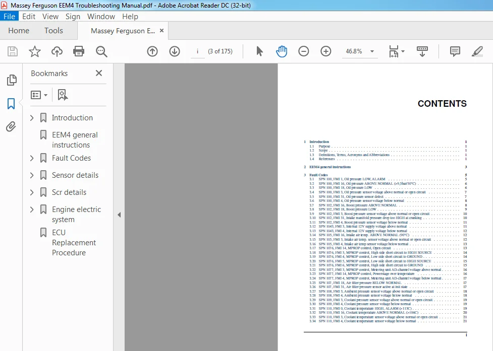
TABLE OF CONTENTS:
Massey Ferguson EEM4 Troubleshooting Manual
1 Introduction 1
1 1 Purpose 1
1 2 Scope 1
1 3 Definitions, Terms, Acronyms and Abbreviations 1
1 4 References 1
2 EEM4 general instructions 3
3 Fault Codes 5
3 1 SPN 100, FMI 1, Oil pressure LOW, ALARM 5
3 2 SPN 100, FMI 16, Oil pressure ABOVE NORMAL (>9,5bar/30°C) 6
3 3 SPN 100, FMI 18, Oil pressure LOW 6
3 4 SPN 100, FMI 3, Oil pressure sensor voltage above normal or open circuit 7
3 5 SPN 100, FMI 31, Oil pressure sensor defect 7
3 6 SPN 100, FMI 4, Oil pressure sensor voltage below normal 8
3 7 SPN 102, FMI 16, Boost pressure ABOVE NORMAL 8
3 8 SPN 102, FMI 18, Boost pressure LOW 9
3 9 SPN 102, FMI 3, Boost pressure sensor voltage above normal or open circuit 10
3 10 SPN 102, FMI 31, Intake manifold pressure drop too HIGH at cranking 10
3 11 SPN 102, FMI 4, Boost pressure sensor voltage below normal 11
3 12 SPN 1043, FMI 3, Internal 12V supply voltage above normal 11
3 13 SPN 1043, FMI 4, Internal 12V supply voltage below normal 12
3 14 SPN 105, FMI 16, Intake air temp ABOVE NORMAL (90°C) 12
3 15 SPN 105, FMI 3, Intake air temp sensor voltage above normal or open circuit 12
3 16 SPN 105, FMI 4, Intake air temp sensor voltage below normal 13
3 17 SPN 1076, FMI 14, MPROP control, Open circuit 13
3 18 SPN 1076, FMI 3, MPROP control, High side short circuit to HIGH SOURCE 14
3 19 SPN 1076, FMI 4, MPROP control, Low side short circuit to GROUND 14
3 20 SPN 1076, FMI 5, MPROP control, Low side short circuit to HIGH SOURCE 15
3 21 SPN 1076, FMI 6, MPROP control, High side short circuit to GROUND 15
3 22 SPN 1077, FMI 3, MPROP control, Metering unit AD-channel voltage above normal 16
3 23 SPN 1077, FMI 14, MPROP control, Powerstage over temperature 16
3 24 SPN 1077, FMI 4, MPROP control, Metering unit AD-channel voltage below normal 17
3 25 SPN 107, FMI 18, Air filter pressure BELOW NORMAL 17
3 26 SPN 107, FMI 31, Air filter pressure sensor active at init state 17
3 27 SPN 108, FMI 3, Ambient pressure sensor voltage above normal or open circuit 18
3 28 SPN 108, FMI 4, Ambient pressure sensor voltage below normal 18
3 29 SPN 109, FMI 3, Coolant pressure sensor voltage above normal or open circuit 19
3 30 SPN 109, FMI 4, Coolant pressure sensor voltage below normal 19
3 31 SPN 110, FMI 0, Coolant temperature HIGH, ALARM (>113C) 19
3 32 SPN 110, FMI 16, Coolant temperature ABOVE NORMAL (>106C) 20
3 33 SPN 110, FMI 3, Coolant temperature sensor voltage above normal or open circuit 21
3 34 SPN 110, FMI 4, Coolant temperature sensor voltage below normal 21
i
3 35 SPN 1136, FMI 0, ECU over temperature HIGH, ALARM 22
3 36 SPN 1136, FMI 3, ECU temperature sensor voltage above normal or open circuit 22
3 37 SPN 1136, FMI 4, ECU temperature sensor voltage below normal 23
3 38 SPN 1321, FMI 3, Start relay high side voltage above normal 23
3 39 SPN 1321, FMI 6, Start relay high side current above normal 23
3 40 SPN 1485, FMI 11, ECU internal power off ERROR at previous afterrun 24
3 41 SPN 1485, FMI 31, Main relay early opening at previous afterrun 24
3 42 SPN 157, FMI 0, Rail pressure above normal 25
3 43 SPN 157, FMI 15, Rail pressure controller, Positive deviation 25
3 44 SPN 157, FMI 16, Rail pressure ABOVE NORMAL 27
3 45 SPN 157, FMI 17, Rail pressure controller, Negative deviation 27
3 46 SPN 157, FMI 18, Rail pressure below normal 28
3 47 SPN 157, FMI 2, Rail pressure raw value is intermittent 29
3 48 SPN 157, FMI 20, Rail pressure raw value is above maximum offset 30
3 49 SPN 157, FMI 21, Rail pressure raw value is below minimum offset 30
3 50 SPN 157, FMI 3, Rail pressure sensor voltage above normal or open circuit 31
3 51 SPN 157, FMI 31, Rail pressure, Leakage detected by quantity balance 31
3 52 SPN 157, FMI 4, Rail pressure sensor voltage below normal 32
3 53 SPN 1639, FMI 18, Fan control underspeed or no signal detected 33
3 54 SPN 1639, FMI 19, Fan speed request CAN signal missing 33
3 55 SPN 168, FMI 0, Battery voltage ABOVE NORMAL 34
3 56 SPN 168, FMI 1, Battery voltage BELOW NORMAL (< 7,8 V) 34
3 57 SPN 168, FMI 3, Battery voltage sensor, voltage above normal 34
3 58 SPN 168, FMI 4, Battery voltage sensor, voltage below normal 35
3 59 SPN 171, FMI 19, Ambient temperature CAN signal missing 35
3 60 SPN 171, FMI 3, Ambient temperature sensor voltage above normal or open circuit 35
3 61 SPN 171, FMI 4, Ambient temperature sensor voltage below normal 36
3 62 SPN 174, FMI 0, Fuel inlet temperature HIGH, ALARM (>85°C) 36
3 63 SPN 174, FMI 3, Fuel temperature sensor voltage above normal or open circuit 37
3 64 SPN 174, FMI 4, Fuel temperature sensor voltage below normal 37
3 65 SPN 1761, FMI 1, DEF tank EMPTY 38
3 66 SPN 1761, FMI 18, DEF tank LEVEL LOW 38
3 67 SPN 1761, FMI 3, DEF tank level sensor voltage above normal or open circuit 38
3 68 SPN 1761, FMI 4, DEF tank level sensor voltage below normal 39
3 69 SPN 2791, FMI 0, EGR Valve temperature alert 39
3 70 SPN 2791, FMI 10, EGR Valve torque limited 40
3 71 SPN 2791, FMI 11, EGR Valve short cut 40
3 72 SPN 2791, FMI 12, EGR Valve initialization error 40
3 73 SPN 2791, FMI 14, EGR Valve overload 41
3 74 SPN 2791, FMI 16, EGR Valve temperature warning 41
3 75 SPN 2791, FMI 19, EGR Valve communication error 42
3 76 SPN 2791, FMI 31, EGR Valve not present 42
3 77 SPN 2791, FMI 7, EGR Valve position deviation 42
3 78 SPN 29, FMI 3, Throttle 2 sensor above normal or open circuit (IDLE) 43
3 79 SPN 29, FMI 4, Throttle 2 sensor below normal (IDLE) 43
3 80 SPN 3031, FMI 10, DEF tank temperature abnormal rate of change at heating cycle 44
3 81 SPN 3031, FMI 14, DEF tank maximum defrost time exceeded 44
3 82 SPN 3031, FMI 16, DEF tank temperature ABOVE normal 45
3 83 SPN 3031, FMI 3, DEF tank temp sensor voltage above normal or open circuit 45
3 84 SPN 3031, FMI 4, DEF tank temp sensor voltage below normal 46
3 85 SPN 3361, FMI 11, DEF dosing valve overheat protection 46
3 86 SPN 3361, FMI 14, DEF dosing valve current abnormal behaviour 47
3 87 SPN 3361, FMI 3, DEF dosing valve low side short circuit to HIGH SOURCE 47
3 88 SPN 3361, FMI 31, DEF dosing valve powerstage driver chip over temperature 48
3 89 SPN 3361, FMI 4, DEF dosing valve high side short circuit 48
3 90 SPN 3361, FMI 5, DEF dosing valve high side short circuit to HIGH SOURCE or open load 49
3 91 SPN 3361, FMI 6, DEF dosing valve low side short circuit to GROUND or open load 49
3 92 SPN 3363, FMI 3, DEF tank heater coolant valve solenoid short circuit to HIGH SOURCE 49
ii
3 93 SPN 3363, FMI 31, DEF tank heater ECU power stage over temperature 50
3 94 SPN 3363, FMI 4, DEF tank heater coolant valve solenoid short circuit to GROUND 50
3 95 SPN 3363, FMI 5, DEF tank heater coolant valve solenoid open circuit 51
3 96 SPN 3509, FMI 31, 5Vdc Supply 1 voltage out of range 51
3 97 SPN 3510, FMI 31, 5Vdc Supply 2 voltage out of range 52
3 98 SPN 3511, FMI 31, 5Vdc Supply 3 voltage out of range 52
3 99 SPN 3512, FMI 3, 12V sensor supply 1 voltage above normal 52
3 100 SPN 3512, FMI 4, 12V sensor supply 1 voltage below normal 53
3 101 SPN 3, FMI 14, Number of injections is limited by quantity balance of high pressure pump 53
3 102 SPN 4090, FMI 16, SCR system malfunction: NOx emission too HIGH 54
3 103 SPN 4090, FMI 18, SCR system malfunction: Measured NOx emission implausible 54
3 104 SPN 4201, FMI 2, Crank speed signal erratic, too much noise pulses 55
3 105 SPN 4201, FMI 31, Crankshaft speed sensor signal missing 55
3 106 SPN 4332, FMI 0, SCR system ERROR: DEF over pressure detected 56
3 107 SPN 4332, FMI 11, SCR system ERROR: Pumped-Dosed quantities balance error 57
3 108 SPN 4332, FMI 14, SCR system ERROR: Pressure drop test failure 57
3 109 SPN 4332, FMI 16, SCR system ERROR: DEF dosing pressure above normal 58
3 110 SPN 4332, FMI 18, SCR system ERROR: DEF dosing pressure below normal 59
3 111 SPN 4332, FMI 31, SCR system ERROR: Emptying not completed at previous shutdown 59
3 112 SPN 4334, FMI 3, DEF pressure sensor voltage above normal or open circuit 60
3 113 SPN 4334, FMI 4, DEF pressure sensor voltage below normal 60
3 114 SPN 4340, FMI 3, DEF suction line heater control circuit short circuit to HIGH SOURCE 61
3 115 SPN 4340, FMI 31, DEF suction line heater ECU power stage over temperature 61
3 116 SPN 4340, FMI 4, DEF suction line heater control circuit short circuit to GROUND 62
3 117 SPN 4340, FMI 5, DEF suction line heater control circuit open circuit 62
3 118 SPN 4342, FMI 3, DEF backflow line heater control circuit short circuit to HIGH SOURCE 62
3 119 SPN 4342, FMI 31, DEF backflow line heater ECU power stage over temperature 63
3 120 SPN 4342, FMI 4, DEF backflow line heater control circuit short circuit to GROUND 63
3 121 SPN 4342, FMI 5, DEF backflow line heater control circuit open circuit 64
3 122 SPN 4344, FMI 12, DEF supply module temperature measurement module is not responding 64
3 123 SPN 4344, FMI 2, DEF supply module heater temperature signal in invalid range 64
3 124 SPN 4344, FMI 3, DEF supply module heater control circuit short circuit to HIGH SOURCE 65
3 125 SPN 4344, FMI 31, DEF supply module heater ECU power stage over temperature 65
3 126 SPN 4344, FMI 4, DEF supply module heater control circuit short circuit to GROUND 66
3 127 SPN 4344, FMI 8, DEF supply module heater temperature signal in failure range 66
3 128 SPN 4346, FMI 3, DEF pressure line heater control circuit short circuit to HIGH SOURCE 67
3 129 SPN 4346, FMI 31, DEF pressure line heater ECU power stage over temperature 67
3 130 SPN 4346, FMI 4, DEF pressure line heater control circuit short circuit to GROUND 68
3 131 SPN 4346, FMI 5, DEF pressure line heater control circuit open circuit 68
3 132 SPN 4354, FMI 3, DEF suction line heater relay low side (line relay) open circuit 68
3 133 SPN 4354, FMI 4, DEF suction line heater relay high side (heater, main relay) open circuit 69
3 134 SPN 4355, FMI 3, DEF backflow line heater relay low side (line relay) open circuit 69
3 135 SPN 4355, FMI 4, DEF backflow line heater relay high side (heater, main relay) open circuit 70
3 136 SPN 4356, FMI 3, DEF supply module heater relay low side open circuit 70
3 137 SPN 4356, FMI 4, DEF supply module heater relay high side (heater, main relay) open circuit 71
3 138 SPN 4356, FMI 5, DEF supply module heater relay open circuit 71
3 139 SPN 4357, FMI 3, DEF pressure line heater relay low side (line relay) open circuit 71
3 140 SPN 4357, FMI 4, DEF pressure line heater relay high side (heater, main relay) open circuit 72
3 141 SPN 4360, FMI 2, SCR catalyst inlet gas temp sensor plausibility test FAILED 72
3 142 SPN 4360, FMI 3, SCR catalyst inlet gas temp sensor voltage above normal or open circuit 73
3 143 SPN 4360, FMI 4, SCR catalyst inlet gas temp sensor voltage below normal 73
3 144 SPN 4363, FMI 2, SCR catalyst outlet gas temp sensor plausibility test FAILED 74
3 145 SPN 4363, FMI 3, SCR catalyst outlet gas temp sensor voltage above normal or open circuit 74
3 146 SPN 4363, FMI 4, SCR catalyst outlet gas temp sensor voltage below normal 75
3 147 SPN 4374, FMI 14, DEF pump motor speed permanent deviation 75
3 148 SPN 4374, FMI 31, DEF pump motor not available for actuation 76
3 149 SPN 4374, FMI 8, DEF pump motor speed deviation 76
3 150 SPN 4375, FMI 3, DEF pump motor control signal short circuit to HIGH SOURCE 76
iii
3 151 SPN 4375, FMI 31, DEF pump motor control powerstage over temperature 77
3 152 SPN 4375, FMI 4, DEF pump motor control signal short circuit to GROUND 77
3 153 SPN 4375, FMI 5, DEF pump motor control signal current below normal or open circuit 78
3 154 SPN 4376, FMI 3, DEF pump direction valve low side short circuit to HIGH SOURCE 78
3 155 SPN 4376, FMI 31, DEF pump direction valve low side control powerstage over temperature 79
3 156 SPN 4376, FMI 4, DEF pump direction valve low side short circuit to GROUND 79
3 157 SPN 4376, FMI 5, DEF pump direction valve low side current below normal or open circuit 80
3 158 SPN 520200, FMI 16, Powerstages could be disabled due to high Battery voltage 80
3 159 SPN 520200, FMI 18, Powerstages could be disabled due to low Battery voltage 81
3 160 SPN 520201, FMI 19, Bus off Engine CAN (1M) 81
3 161 SPN 520202, FMI 3, ECU Main Relay 0 Short circuit to HIGH SOURCE 82
3 162 SPN 520202, FMI 4, ECU Main Relay 0 short circuit to GROUND 82
3 163 SPN 520203, FMI 3, ECU Main Relay 1 Short circuit to HIGH SOURCE 83
3 164 SPN 520203, FMI 4, ECU Main Relay 1 short circuit to GROUND 83
3 165 SPN 520204, FMI 3, ECU Main Relay 2 Short circuit to HIGH SOURCE 84
3 166 SPN 520204, FMI 4, ECU Main Relay 2 short circuit to GROUND 84
3 167 SPN 520205, FMI 31, Error in torque control input 84
3 168 SPN 520206, FMI 31, Chip error in the CY33x power stage component 1 85
3 169 SPN 520208, FMI 31, Rail PRV recognised as OPEN 85
3 170 SPN 520209, FMI 31, Error in the plausibility of the injection energizing time 86
3 171 SPN 520210, FMI 12, Error in the plausibility of the start of energising angles 86
3 172 SPN 520211, FMI 31, Chip error in the CY33x power stage component 0 87
3 173 SPN 520212, FMI 31, Diagnostic fault check to report the NTP error in ADC monitoring 87
3 174 SPN 520213, FMI 31, Diagnostic fault check to report the ADC test error 88
3 175 SPN 520214, FMI 31, Diagnostic fault check to report the error in Voltage ratio in ADC monitoring 88
3 176 SPN 520215, FMI 31, Diagnostic fault check to report errors in query-/response-communication 89
3 177 SPN 520216, FMI 31, Diagnostic fault check to report errors in SPI-communication 89
3 178 SPN 520217, FMI 31, Diagnostic fault check to report multiple error while checking the complete
ROM-memory 89
3 179 SPN 520218, FMI 31, Loss of synchronization sending bytes to the MM from CPU 90
3 180 SPN 520219, FMI 31, DFC to set a torque limitation once an error is detected before MoCSOPs
error reaction is set 90
3 181 SPN 520220, FMI 31, Wrong set response time 90
3 182 SPN 520221, FMI 31, Too many SPI errors during MoCSOP execution 91
3 183 SPN 520222, FMI 31, Diagnostic fault check to report the error in undervoltage monitoring 91
3 184 SPN 520223, FMI 31, Diagnostic fault check to report that WDA is not working correct 91
3 185 SPN 520224, FMI 31, OS timeout in the shut off path test Failure setting the alarm task period 92
3 186 SPN 520225, FMI 31, Diagnostic fault check to report that the positive test failed 92
3 187 SPN 520226, FMI 31, Diagnostic fault check to report the timeout in the shut off path test 93
3 188 SPN 520227, FMI 31, Diagnostic fault check to report the error in overvoltage monitoring 93
3 189 SPN 520228, FMI 12, Cy320 Multiple Power Supply module SPI/COM-Error 93
3 190 SPN 520229, FMI 13, Fast A/D Converter calibration error 94
3 191 SPN 520230, FMI 31, Engine specification mismatch 94
3 192 SPN 520231, FMI 31, PTO input error 94
3 193 SPN 520232, FMI 31, Bad digital input configuration 95
3 194 SPN 520234, FMI 31, Diagnostic fault check to report ABE active due to undervoltage detection 95
3 195 SPN 520235, FMI 31, Diagnostic fault check to report ABE active due to overvoltage detection 95
3 196 SPN 520236, FMI 31, Diagnostic fault check to report WDA/ABE active due to unknown reason 96
3 197 SPN 520237, FMI 31, Customer fault 1 via digital input 96
3 198 SPN 520238, FMI 31, Customer fault 2 via digital input 96
3 199 SPN 520239, FMI 3, DEF dosing valve after cooler voltage above normal or short to HIGH
SOURCE 96
3 200 SPN 520239, FMI 5, DEF dosing valve after cooler current below normal or open circuit 97
3 201 SPN 520239, FMI 6, DEF dosing valve after cooler current above normal or short to GROUND 97
3 202 SPN 520240, FMI 31, Injector bank 0 short circuit 98
3 203 SPN 520241, FMI 31, Injector bank 1 short circuit 98
3 204 SPN 520242, FMI 31, Injector bank 2 short circuit 99
3 205 SPN 520243, FMI 31, Rail PRV is forced to open; perform pressure increase 100 iv
3 206 SPN 520244, FMI 31, Rail PRV is forced to open; perform pressure shock 100
3 207 SPN 520245, FMI 31, Rail PRV reached maxium allowed opening count 101
3 208 SPN 520246, FMI 31, Rail PRV reached maximun allowed open time 102
3 209 SPN 520247, FMI 31, Reported SPI and COM-Errors of a Cy146 102
3 210 SPN 520248, FMI 31, Reported SPI and COM-Errors of a Cy146 102
3 211 SPN 520249, FMI 31, Reported SPI and COM-Errors of a Cy146 103
3 212 SPN 520250, FMI 31, Reported SPI and COM-Errors of a Cy146 103
3 213 SPN 520251, FMI 31, Reported SPI and COM-Errors of a Cy146 103
3 214 SPN 521000, FMI 2, DEF pump temperature signal duty cycle in invalid range 104
3 215 SPN 521000, FMI 8, DEF pump temperature signal duty cycle in failure range 104
3 216 SPN 521001, FMI 3, DEF heater main relay circuit short circuit to HIGH SOURCE 104
3 217 SPN 521001, FMI 31, DEF heater main relay ECU power stage over temperature 105
3 218 SPN 521001, FMI 4, DEF heater main relay open circuit 105
3 219 SPN 521002, FMI 3, DEF pump direction valve high side short circuit to HIGH SOURCE 106
3 220 SPN 521002, FMI 31, DEF pump direction valve high side control powerstage over temperature 106
3 221 SPN 521002, FMI 4, DEF pump direction valve high side short circuit to GROUND 107
3 222 SPN 521002, FMI 5, DEF pump direction valve high side current below normal or open circuit 107
3 223 SPN 521003, FMI 3, DEF heater main relay control circuit short circuit to HIGH SOURCE 107
3 224 SPN 521003, FMI 4, DEF heater main relay control circuit short circuit to GROUND 108
3 225 SPN 521004, FMI 11, Downstream NOx sensor missing 108
3 226 SPN 521004, FMI 12, Downstream NOx sensor stability time exceeded 109
3 227 SPN 521004, FMI 2, Downstream NOx sensor plausibility test FAILED 109
3 228 SPN 521005, FMI 11, Upstream NOx sensor missing 110
3 229 SPN 521005, FMI 12, Upstream NOx sensor stability time exceeded 110
3 230 SPN 521005, FMI 2, Upstream NOx sensor plausibility test FAILED 111
3 231 SPN 521006, FMI 12, Nox conversion plausibility test FAILED 111
3 232 SPN 521007, FMI 10, SCR system ERROR: DEF backflow line blocked or implausible 112
3 233 SPN 521007, FMI 14, SCR system ERROR: DEF pressure line or dosing valve blocked 112
3 234 SPN 521007, FMI 31, SCR system ERROR: DEF pressure stabilisation failure 113
3 235 SPN 521008, FMI 0, SCR system ERROR: DEF pressure reduction failure 114
3 236 SPN 521008, FMI 1, SCR system ERROR: DEF pressure build up failure 114
3 237 SPN 521010, FMI 14, DEF tank heater coolant valve solenoid high side short circuit to HIGH
SOURCE 115
3 238 SPN 521010, FMI 3, DEF tank heater coolant valve solenoid low side short circuit to HIGH
SOURCE 115
3 239 SPN 521010, FMI 31, DEF tank heater coolant valve low side power stage over temperature 116
3 240 SPN 521010, FMI 4, DEF tank heater coolant valve solenoid high side short circuit to GROUND 116
3 241 SPN 521010, FMI 5, DEF tank heater coolant valve solenoid low side open circuit 117
3 242 SPN 521010, FMI 6, DEF tank heater coolant valve solenoid low side short circuit to GROUND 117
3 243 SPN 626, FMI 3, Grid heater relay voltage above normal or short to HIGH SOURCE 117
3 244 SPN 626, FMI 5, Grid heater relay current below normal or open circuit 118
3 245 SPN 626, FMI 6, Grid heater relay current above normal or short to GROUND 118
3 246 SPN 639, FMI 19, Bus off Vehicle CAN (250k) 119
3 247 SPN 651, FMI 14, Solenoid valve 1, Short circuit 119
3 248 SPN 651, FMI 5, Solenoid valve 1, Current below normal: Open circuit 120
3 249 SPN 651, FMI 6, Solenoid valve 1, Current above normal: Short circuit between cables 120
3 250 SPN 652, FMI 14, Solenoid valve 2, Short circuit 121
3 251 SPN 652, FMI 5, Solenoid valve 2, Current below normal: Open circuit 121
3 252 SPN 652, FMI 6, Solenoid valve 2, Current above normal: Short circuit between cables 122
3 253 SPN 653, FMI 14, Solenoid valve 3, Short circuit 122
3 254 SPN 653, FMI 5, Solenoid valve 3, Current below normal: Open circuit 123
3 255 SPN 653, FMI 6, Solenoid valve 3, Current above normal: Short circuit between cables 123
3 256 SPN 654, FMI 14, Solenoid valve 4, Short circuit 124
3 257 SPN 654, FMI 5, Solenoid valve 4, Current below normal: Open circuit 124
3 258 SPN 654, FMI 6, Solenoid valve 4, Current above normal: Short circuit between cables 125
3 259 SPN 655, FMI 14, Solenoid valve 5, Short circuit 126
3 260 SPN 655, FMI 5, Solenoid valve 5, Current below normal: Open circuit 126
3 261 SPN 655, FMI 6, Solenoid valve 5, Current above normal: Short circuit between cables 127
v
3 262 SPN 656, FMI 14, Solenoid valve 6, Short circuit 127
3 263 SPN 656, FMI 5, Solenoid valve 6, Current below normal: Open circuit 128
3 264 SPN 656, FMI 6, Solenoid valve 6, Current above normal: Short circuit between cables 128
3 265 SPN 657, FMI 14, Solenoid valve 7, Short circuit 129
3 266 SPN 657, FMI 5, Solenoid valve 7, Current below normal: Open circuit 129
3 267 SPN 657, FMI 6, Solenoid valve 7, Current above normal: Short circuit between cables 130
3 268 SPN 677, FMI 3, Start relay low side voltage above normal or short to HIGH SOURCE 130
3 269 SPN 677, FMI 5, Start relay current below normal or open circuit 130
3 270 SPN 677, FMI 3, Start relay low side current above normal 131
3 271 SPN 723, FMI 2, Number and/or position of the camshaft pulses implausible – disturbed signal 131
3 272 SPN 723, FMI 31, Cam speed sensor signal missing 132
3 273 SPN 723, FMI 8, Signal deviation between crankshaft and camshaft too large 133
3 274 SPN 729, FMI 3, Grid heater voltage above normal 133
3 275 SPN 729, FMI 4, Grid heater voltage below normal 134
3 276 SPN 84, FMI 3, Vechicle speed sensor short to HIGH SOURCE 134
3 277 SPN 84, FMI 4, Vechicle speed sensor short to GROUND 135
3 278 SPN 91, FMI 3, Throttle 1 sensor above normal or open circuit (IDLE) 135
3 279 SPN 91, FMI 4, Throttle 1 sensor below normal (IDLE) 135
3 280 SPN 94, FMI 16, Fuel main filter inlet pressure ABOVE NORMAL 136
3 281 SPN 94, FMI 18, Fuel main filter inlet pressure BELOW NORMAL 136
3 282 SPN 94, FMI 3, Fuel main filter inlet pressure sensor voltage above normal or open circuit 137
3 283 SPN 94, FMI 31, Fuel main filter inlet pressure ALARM, out of safe operating range 138
3 284 SPN 94, FMI 4, Fuel main filter inlet pressure sensor voltage below normal 138
3 285 SPN 974, FMI 3, Throttle 3 sensor above normal or open circuit (IDLE) 139
3 286 SPN 974, FMI 4, Throttle 3 sensor below normal (IDLE) 139
3 287 SPN 977, FMI 3, Fan control output short circuit to HIGH SOURCE 140
3 288 SPN 977, FMI 5, Fan control output open circuit 140
3 289 SPN 977, FMI 6, Fan control output current above normal 140
3 290 SPN 97, FMI 31, Water in fuel 141
4 Sensor details 143
4 1 Engine sensors overview 143
4 2 Oil pressure sensor 143
4 3 Coolant temperature sensor 144
4 4 Fuel pressure sensor 146
4 5 Fuel temperature sensor 147
4 6 Crankshaft speed sensor 149
4 7 Camshaft speed sensor 149
4 8 NOx sensor 150
4 9 Exhaust gas temperature sensor 150
4 10 Boost pressure sensor 151
4 11 Intake air temperature sensor 152
4 12 Rail pressure sensor 153
4 13 Coolant pressure sensor 155
5 Scr details 157
5 1 SCR system overview 157
5 2 Supply module 157
5 3 Dosing module 160
6 Engine electric system 161
6 1 Grid heater solenoid 161
6 2 Start Relay 161
6 3 4-cyl engine injector harness 162
6 4 6-cyl engine injector harness 162
6 5 7-cyl engine injector harness 162
6 6 Engine ECU power supply 162
7 ECU Replacement Procedure 167
MASSEY FERGUSON EEM4 TROUBLESHOOTING MANUAL – PDF DOWNLOAD:
IMAGES PREVIEW OF THE MANUAL:


PLEASE NOTE:
- This is the SAME exact manual used by your dealers to fix your vehicle.
- The same can be yours in the next 2-3 mins as you will be directed to the download page immediately after paying for the manual.
- Any queries / doubts regarding your purchase, please feel free to contact [email protected]