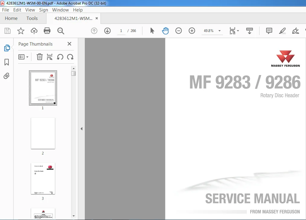
Massey Ferguson EU Hay Equipment MF 9283 9286 Rotary Disc Header Service Manual – PDF DOWNLOAD
Original price was: $86.95.$31.95Current price is: $31.95.
Massey Ferguson EU Hay Equipment MF 9283 9286 Rotary Disc Header Service Manual – PDF DOWNLOAD
Description
Massey Ferguson EU Hay Equipment MF 9283 9286 Rotary Disc Header Service Manual – PDF DOWNLOAD
DESCRIPTION:
Massey Ferguson EU Hay Equipment MF 9283 9286 Rotary Disc Header Service Manual – PDF DOWNLOAD
General information
Introduction to this service manual
This service manual gives information from engineering tests, operating data, and the latest service techniques at the time of publication. Read this service manual carefully before doing any service on the machine. The photos and illustrations used in this service manual were current at the time of publication. Production changes can cause machines to vary from the photos and the illustrations. The manufacturer reserves the right to redesign and change machines as necessary without notification.
Units of measurement
Measurements are given in metric units followed by the equivalent in U S units. Hardware sizes are given in millimeters for metric hardware and inches for U S hardware.
Table of contents
This manual has a table of contents at the front. The table of contents shows the divisions. The individual divisions also have a table of contents.
Page numbers
All pages have two numbers, such as 01-25. The first number shows the divis ion. The second number shows the page in the division. Page numbers occur on the lower right-hand or lower left-hand corner of each page.
TABLE OF CONTENTS:
Massey Ferguson EU Hay Equipment MF 9283 9286 Rotary Disc Header Service Manual – PDF DOWNLOAD
1 General 1-1
1 1 General information 1-3
1 1 1 Introduction to this service manual 1-3
1 1 2 Units of measurement 1-3
1 1 3 Table of contents 1-3
1 1 4 Page numbers 1-3
1 1 5 lntended use 1-3
1 1 6 Proper disposai of waste 1-3
1 2 General safety 1-5
1 2 1 Safety symbol 1-5
1 2 2 Safety messages 1-5
1 2 3 Information messages 1-5
1 2 4 Safety signs 1-5
1 2 5 Safety and informational signs 1-6
1 2 6 Accumulator safety 1-8
1 2 7 A word to the technician 1-8
1 2 8 The service manual 1-9
1 3 Operation 1-10
1 3 1 Prepare for operation 1-10
1 3 2 General information 1-10
1 3 3 Persona! protective equipment 1-1 1
1 3 4 Seat instructions 1-1 1
1 3 5 Shield and guards 1-1 2
1 3 6 Exhaust warning 1-1 2
1 3 7 Flying debris 1-1 3
1 3 8 Handrails 1-1 3
1 3 9 Agricultural chemicals 1-1 3
1 3 10 Travel on public roads 1-1 4
1 4 Maintenance 1-15
1 4 1 General maintenance information 1-1 5
1 4 2 Boit torque values 1-1 6
1 4 3 Fire prevention and first aid 1-1 9
1 4 4 High pressure leaks 1-20
1 4 5 Tire safety 1-20
1 4 6 Replacement parts 1-21
1 4 7 Remove an eccentric locking collar 1-21
1 4 8 lnstall an eccentric locking collar 1-21
1 4 9 Remove a gib key 1-22
1 4 10 lnstall a gib key 1-23
1 5 Specifications 1-24
1 5 1 Maximum roading speed 1-24
1 5 2 Dimensions and weights 1-24
1 5 3 Header specifications 1-24
1 5 4 Cutterbed specifications 1-24
1 5 5 Cutterbed boit torque 1-25
1 5 6 Conditioner specifications 1-25
1 5 7 Lubrication specifications 1-25
1 6 Machine identification 1-27
1 6 1 Machine identification 1-27
1 6 2 Serial number plate 1-27
1 6 3 Serial number description 1-27
Rotary Dise Header
4283612M1
Table of contents
1 7 Machine description 1-29
1 7 1 Description 1-2 9
1 7 2 Cutterbed 1-2 9
1 7 3 Conditioner 1-2 9
1 7 4 Swathboard 1-30
1 7 5 Forming shields 1-3 0
1 8 Component location 1-31
1 8 1 Component location 1-3 1
1 8 2 Component access 1-3 1
1 9 Troubleshooting 1-32
1 9 1 Header troubleshooting 1-3 2
1 9 2 Cutterbed troubleshooting 1-3 3
1 9 3 Conditioner troubleshooting 1-3 4
1 9 4 Crop conditioning and windrow formation 1-3 5
1 9 5 Cutoff quality 1-3 5
2 Drive system 2-1
2 1 Conditioner drive belt 2-3
2 1 1 Banded drive belt 2-3
2 1 2 lnstall a belt 2-3
2 1 3 Belt run-in procedure 2-4
2 2 Helper roll drive belt 2-6
2 2 1 Replace the helper roll drive belt 2-6
2 2 2 Adjust the helper roll drive belt 2-6
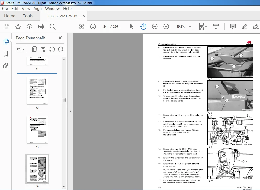
2 3 Header drive gearbox 2-7
2 3 1 Header drive gearbox components 2-7
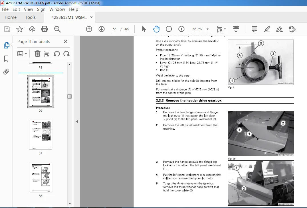
2 3 2 Special tools (header drive gearbox) 2-8
2 3 3 Remove the header drive gearbox 2-8
2 3 4 Disassemble the header drive gearbox 2-10
2 3 5 Examine the header drive gearbox 2-1 6
2 3 6 Assemble the header drive gearbox 2-1 7
2 3 7 lnstall the header drive gearbox 2-2 1
2 3 8 Adjust the header drive gearbox 2-2 3
2 4 Conditioner drive tensioner 2-25
2 4 1 Header drive tensioner components 2-2 5
2 4 2 Disassemble the header drive tensioner 2-2 6
2 4 3 Examine the conditioner drive tensioner 2-2 6
2 4 4 Assemble the conditioner drive tensioner 2-2 7
3 Hydraulic system 3-1
3 1 General information 3-3
3 1 1 General hydraulic information 3-3
3 1 1 1 Hydraulic system 3-3
3 2 Header drive motor 3-4
3 2 1 Header drive motor components 3-4
3 2 2 Examine the case drain leakage 3-5
3 2 3 Remove the header drive motor 3-7
3 2 4 Disassemble the header drive motor 3-9
3 2 5 Assemble the header drive motor 3-1 6
3 2 6 lnstall the header drive motor 3-2 5
3 3 Conditioner drive motor (double conditioner) 3-29
3 3 1 Remove the conditioner drive motor (double conditioner) 3-2 9
3 3 2 lnstall the conditioner drive motor (double conditioner) 3-2 9
3 4 Conditioner roll cylinders 3-30
3 4 1 Conditioner roll cylinder components 3-3 0
3 4 2 Remove the conditioner roll cylinders 3-30
Rotary Dise Header
4283612M1
Table of contents
3 4 3 Disassemble the conditioner roll cylinder 3-3 1
3 4 4 Examine the conditioner roll cylinder 3-3 1
3 4 5 Assemble the conditioner roll cylinder 3-3 2
3 4 6 lnstall the conditioner roll cylinder 3-3 2
3 4 7 Adjust the pressure of the conditioner roll cylinders 3-3 3
3 5 Accumulator 3-34
3 5 1 General information 3-3 4
3 5 2 Remove the accumulator 3-3 4
3 5 3 Discharge the accumulator 3-3 4
3 5 4 Charge the accumulator 3-3 5
3 5 5 lnstall the accumulator 3-3 5
4 Electrical system 4-1
4 1 Basic electrical troubleshooting 4-3
4 1 1 Basic troubleshooting procedures 4-3
4 1 2 Tools 4-4
4 1 3 Continuity check 4-4
4 1 4 Voltage check 4-5
4 2 Connectors 4-6
4 2 1 Examine a connector 4-6
4 2 2 Terminal numbers 4-6
4 2 3 Pins and sockets 4-7
4 2 4 Replace a Packard connector 4-8
4 2 5 Replace an AMP connector 4-8
4 2 6 Replace a Power Cord connector 4-8
4 2 7 Replace a Deutsch connector 4-9
4 3 Header speed sensor 4-11
4 3 1 Electrical sensor location 4-1 1
4 3 2 Adjust the electrical sensors 4-1 1
5 Cutterbed 5-1
5 1 Dises 5-3
5 1 1 Dises 5-3
5 1 2 Dise maintenance 5-3
5 1 3 Remove an inner dise 5-3
5 1 4 lnstall an inner dise 5-4
5 1 5 Remove the outer dise 5-5
5 1 6 lnstall the outer dise 5-7
5 2 Knives 5-9
5 2 1 Knife wedging under dise 5-9
5 2 2 Knife inspection 5-9
5 2 3 Replace a knife 5-10
5 2 4 Knife hardware inspection 5-10
5 3 Cutterbed 5-12
5 3 1 Cutterbed 5-1 2
5 3 2 Cutterbed oil level 5-1 2
5 3 3 Change the cutterbed oil 5-1 2
5 3 4 Lubrication specifications 5-1 4
5 3 5 Cutterbed inspection 5-1 5
5 3 6 Cutterbed components 5-1 6
5 3 7 Remove the cutterbed 5-1 6
5 3 8 Disassemble the cutterbed 5-1 9
5 3 9 Examine the cutterbed 5-20
5 3 10 Assemble the cutterbed 5-2 1
5 3 1 1 Examine the cutterbed for leaks 5-2 3
5 3 1 2 lnstall the cutterbed 5-2 4
5 4 Spindle gear assembly 5-27
Rotary Dise Header
4283612M1
Table of contents
5 4 1 Spindle gear assembly 5-2 7
5 4 2 Remove the spindle gear 5-2 7
5 4 3 Disassemble the spindle gear 5-2 8
5 4 4 Examine the spindle gear 5-2 8
5 4 5 Assemble the spindle gear 5-2 9
5 4 6 lnstall the spindle gear 5-3 0
5 5 ldler gear assembly 5-32
5 5 1 ldler gear assembly 5-3 2
5 5 2 Remove the idler gear 5-3 2
5 5 3 Disassemble the idler gear 5-3 4
5 5 4 Examine the idler gear 5-3 5
5 5 5 Assemble the idler gear 5-3 5
5 5 6 lnstall the idler gear 5-3 6
6 Conditioner 6-1
6 1 Helper roll 6-3
6 1 1 Helper roll components 6-3
6 1 2 Remove the helper roll 6-3
6 1 3 lnstall the helper roll 6-8
6 2 Drive shaft 6-15
6 2 1 Remove the drive shaft – slip tube 6-1 5
6 2 2 lnstall the drive shaft – slip tube 6-1 6
6 2 3 Remove the drive shaft – sol id shaft 6-18
6 2 4 lnstall the drive shaft – solid shaft 6-18
6 3 U-joint 6-20
6 3 1 U-joint components 6-2 0
6 3 2 Remove the U-joints 6-2 0
6 3 3 Disassemble the U-joint 6-2 1
6 3 4 Assemble the U-joint 6-2 3
6 3 5 lnstall the U-joints 6-2 9
6 4 Belts 6-31
6 4 1 Belt maintenance 6-3 1
6 4 2 Replace the conditioner belt 6-3 1
6 4 3 Adjust the conditioner belt 6-3 2
6 4 4 Replace the helper roll belt 6-3 3
6 4 5 Adjust the helper roll belt 6-3 3
6 5 Left conditioner gearbox 6-34
6 5 1 Conditioner gearbox lubrication 6-3 4
6 5 2 Remove the left conditioner gearbox 6-3 4
6 5 3 Conditioner gearbox components – left 6-3 5
6 5 4 Disassemble the left conditioner gearbox 6-3 6
6 5 5 Examine the conditioner gearbox 6-3 6
6 5 6 Assemble the left conditioner gearbox 6-3 7
6 5 7 lnstall the left conditioner gearbox 6-3 8
6 6 Right conditioner gearbox – double conditioner only 6-40
6 6 1 Conditioner gearbox lubrication 6-4 0
6 6 2 Remove the right conditioner gearbox 6-4 0
6 6 3 Conditioner gearbox components – right 6-4 1
6 6 4 Disassemble the right conditioner gearbox 6-4 2
6 6 5 Examine the conditioner gearbox 6-4 2
6 6 6 Assemble the right conditioner gearbox 6-4 3
6 6 7 lnstall the right conditioner gearbox 6-4 4
6 7 Conditioner bearings 6-46
6 7 1 Rem ove a spherical bearing 6-4 6
6 7 2 lnstall a spherical bearing 6-4 7
6 7 3 Remove a bushing bearing 6-4 8
6 7 4 lnstall a bushing bearing 6-4 8
Rotary Dise Header
4283612M1
Table of contents
6 8 Rear conditioner – double conditioner only 6-50
6 8 1 Rear top conditioner – components (double conditioner) 6-50
6 8 2 Remove the rear top conditioner – double conditioner 6-5 1
6 8 3 lnstall the rear top conditioner roll – double conditioner 6-5 2
6 8 4 Rear bottom conditioner components – double conditioner 6-5 5
6 8 5 Remove the rear bottom conditioner – double conditioner 6-5 5
6 8 6 lnstall the rear bottom conditioner – double conditioner 6-5 7
6 9 Front conditioner 6-60
6 9 1 Front top conditioner – components 6-60
6 9 2 Remove the front top conditioner 6-6 1
6 9 3 lnstall the front top conditioner 6-6 2
6 9 4 Front bottom conditioner – components 6-6 3
6 9 5 Remove the front bottom conditioner 6-6 3
6 9 6 lnstall the front bottom conditioner 6-6 6
6 10 Conditioner adjustments 6-71
6 10 1 Examine the conditioner 6-7 1
6 10 2 Conditioner 6-7 1
6 10 3 Conditioner spacing 6-7 1
6 10 3 1 Adjust the conditioner roll spacing 6-7 1
6 10 4 Conditioner spacing indicator 6-7 2
6 10 4 1 Adjust the conditioner spacing indicator – double conditioner 6-7 2
6 10 4 2 Adjust the conditioner spacing indicator – single conditioner 6-7 3
6 10 5 Adjust the conditioner timing 6-7 3
6 10 6 Conditioner pressure 6-7 4
6 10 7 Adjust the conditioner pressure 6-7 4
6 11 Windrow forming shields 6-75
6 1 1 1 Adjust the windrow forming shields 6-7 5
6 1 1 2 Adjust the deflector 6-7 5
6 1 1 3 Adjust the windrow forming deck height 6-7 5
6 12 Swathboard 6-77
6 1 2 1 Swathboard 6-7 7
6 1 2 2 Adjust the swathboard 6-7 7
7 Diagrams 7-1
7 1 Reading wiring diagrams 7-3
7 1 1 Diagram numbers 7-3
7 1 2 Location grids 7-3
7 1 3 Wire breaks 7-4
7 2 Diagram symbols and abbreviations 7-6
7 2 1 Harness and connector identification 7-6
7 2 2 Splices 7-6
7 2 3 CAN signal 7-7
7 3 Electrical diagrams 7-8
7 3 1 Harness abbreviations 7-8
7 3 2 Wire colors 7-8
7 3 3 Main electrical diagram 7-9
7 4 Electrical tables 7-11
7 4 1 Circuit table 7-1 1
7 4 2 Connector function 7-1 2
7 4 3 Connector table 7-1 2
7 4 4 Tractor connector 7-1 3
7 5 Hydraulic schematic 7-15
7 5 1 Hydraulic schematic 7-1 7
8 Index lndex-1
MASSEY FERGUSON EU HAY EQUIPMENT MF 9283 9286 ROTARY DISC HEADER SERVICE MANUAL – PDF DOWNLOAD:
IMAGES PREVIEW OF THE MANUAL:
PLEASE NOTE:
- This is the SAME manual used by the dealers to troubleshoot any faults in your vehicle. This can be yours in 2 minutes after the payment is made.
- Contact us at [email protected] should you have any queries before your purchase or that you need any other service / repair / parts operators manual.
S.V