Massey Ferguson EU Tillage MF2000 Series 2550 Chisel Plough Operator’s Manual – PDF DOWNLOAD
Original price was: $53.95.$23.95Current price is: $23.95.
Massey Ferguson EU Tillage MF2000 Series 2550 Chisel Plough Operator’s Manual – PDF DOWNLOAD
Description
Massey Ferguson EU Tillage MF2000 Series 2550 Chisel Plough Operator’s Manual – PDF DOWNLOAD
FILE DETAILS:
Massey Ferguson EU Tillage MF2000 Series 2550 Chisel Plough Operator’s Manual – PDF DOWNLOAD
Format: PDF
Language: English
Brand: Massey Ferguson
TABLE OF CONTENTS:
Massey Ferguson EU Tillage MF2000 Series 2550 Chisel Plough Operator’s Manual – PDF DOWNLOAD
1 Safety
1 1Introduction
1 1 1Safety alert symbol
1 1 2 Safety messages
1 1 3Informational messages
1 1 4 Safety signs
1 1 5 A word to the operator
1 1 6This manual
1 2 Operation
1 2 1Prepare for operation
1 2 2 General information
1 2 3 Personal protective equipment
1 2 4 Seat instructions
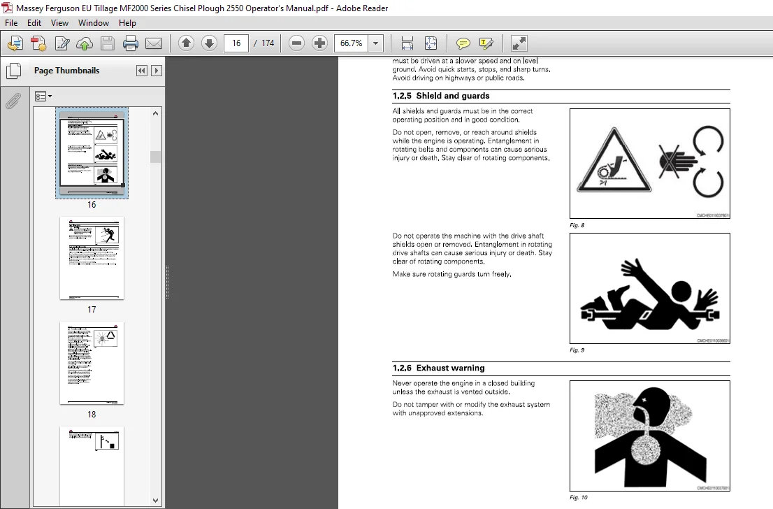
1 2 5 Shield and guards
1 2 6 Exhaust warning
1 2 7 Flying debris
1 2 8 Agricultural chemicals
1 3 Travelon public roads
1 4 Maintenance
1 4 1 General maintenance information
1 4 2 Fire prevention and first aid
1 4 3High pressure leaks
1 4 11Tiro safoty
1 4 5 Replacement parts
1 5 Transport locks
1 6 Marker lamps
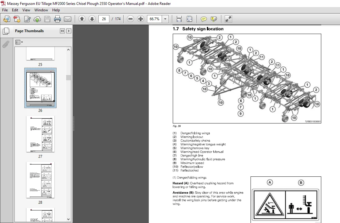
1 7 Safety sign location
2 Introduction
2 1Introduction
2 1 1 Units of measurement
2 1 2 Replacementparts
2 1 3Intendeduse
2 1 4 Proper disposal of waste
2 2 Machine identification
2 2 1 Serial number plate location
2 2 2 Serial number description
2 3 Chisel plough
2 3 1Floating hitch
2 4 Major components
2 5 Operatormanualstorage
3 Operation
3 1 Connecting the machineto thetractor
3 2 Disconnecting the machinefrom thetractor
3 3 Bleeding airfrom the hydraulic lift system
3 4 Bleeding airfrom the hydraulicfold system
3 5 Preparingthe machine fortransport
3 6 Preparing the machine forfield operation
3 7 Beginning field operation
3 7 1 Items to check after first operation
3 8 Leveling the machine
3 8 1 Leveling a machine with the floating hitch front to rear
3 8 2 Leveling the wings to the center frame
3 9 Adjusting the gauge wheels
3 9 1 Adjusting the gauge wheels-hydraulic”
3 10 Operating depth
3 10 1Single point depth control
3 11 Spring shanks
4 Maintenance
4 1 Lubrication points
4 1 1 Lubrication and maintenance chart
4 1 2 Lubrication fitting locations
4 2 Servicing the wheel bearings
4 3 Servicing the tandem pivot bearings
4 4 Storage
4 4 1 Preparing the machine for storage
4 4 2 Preventing corrosion of extended hydraulic cylinders
4 4 3 Removing the machine from storage
5 Troubleshooting
5 1 Troubleshooting
6 Specifications
6 1 Specifications
6 2 Transport dimensions
6 3 Minimum to vehicle weight
6 4 Maximumtransportspeed
6 5 Lubrication specifications
6 6 Tire air pressure
7 Assembly
7 1 Preparing for assembly
7 1 1Service parts
7 2 Assembling the center frame
7 2 1Installingthecenterllft
7 2 2 Installing the center lift hubs and wheels
7 2 3 Installing the center frame mast tubes
7 2 41 Installing the fold anchors
7 2 5 Installing the center frame wing rests
7 3 Assembling the tongue
7 3 1 Installing the tongue
7 3 2 Installing the utility pole
7 4 Installing the center frame shank extension
7 5 Installing the center frame shanks
7 5 1Installing the 650 lb shanks
7 5 2 Installingthe1000 lb shanks
7 6 Installing the slow moving vehicle (SMV) emblem
7 7 lnstalling the inner wings
7 7 1 Mounting the wing frame hinges
7 7 2 Installing the inner wing frarnes
7 7 3 Installing the inner wing frame shank extensrons
7 7 4 Installing the front fold bracket
7 7 5 Installing the rear fold bracket
7 7 6 Installing the inner wing frame wing rests
7 8 lnstallingtheinnerwing frame shanks
7 8 1Installingthe650|bshanks
7 8 2 Installingtho1000|hshanks
7 9 Installingtheinnerwinglifts
7 9 1 Installing the inner wing lift hubs and wheels
7 10 lnstaling the inner wing frame mast tubes
7 11lnstalingtheouterwings
7 11 1 Installing the 14 9 to 16 2 m (49 to 53 ft) outer wing frames
7 11 2 Installing the 14 9 to 16 2 m (49 to 53 ft) outer wing frame shank extensions
7 11 3 Installing the 16 8 to 18 m (55 to 59 ft] outer wrng frames
7 11 4 Installing the 16 8 to 18 m (55 to 59 ft] cuter wing frame shank extensions
7 11 5 Assembling the outer wing latch components
7 12 lnstalingtheouterwingframeshanks
7 12 1Installingthe650lbshanks
7 12 2 Installingthe1000|bshanks
7 13 Instaling the outer wing lifts
7 13 1 Installing the outer wing lift hubs and wheels
7 14 Installing the outer wing frame mast tubes
7 15 Installing the stroke control assembly
7 15 1 Mounting the streke control vavle
7 15 2 Mounting the front of the stroke control
7 15 3 Mounting there arofthestrokecontrol
7 16 Instaling the hydraulic gauge wheels
7 16 1 Installing the gauge wheel mount- hydraulic
7 16 2 Installing the gauge wheel linkage-hydraulic
7 16 3 Assembling the center frame gauge wheel axle-hydraulic
7 16 4 Installing the center frame gauge wheel axle- hydraulic
7 16 5 Assembling the wing frame gauge wheel axle-hydraulic
7 16 6 Installing the wing frame gauge wheel axle-hydraulic
7 16 7 Installing the gauge wheel hubs and wheels-hydraulic
7 16 8 Installing the center frame gauge wheel lift tubes-hydraulic
7 16 9 Installing the wing frame gauge wheel lift tubes—hydraulic
7 17 Installing the marker lamps
7 17 1 Installing the marker lamp harness
7 19 Installing the hydraulics
7 19 1InstallingthecenterIiftcylinders
7 19 2 Installing the wing lift cylinders
7 19 3 Installing the 14 9 to 16 2 m (49 to 53 (1) lift hydraulics
7 19 11 Installing the 16 8 to 13 m (55 to 59 ft] lift hydraulics
7 19 5 Installing the center fold cylinders
7 19 6 Installing the euter fold cylinders
7 19 7 Installing the fold hydraulics
7 20 Shanklocations-30 5cm(1Zinlspacing
7 20 1 14 9 m (49 ft) shank locations -30 5 cm (12 in) spacing
7 20 2 15 5 m (51 ft] shank locations—30 5 cm (12 inl spacing
7 20 3 16 2 m (53 ft] shank locations -30 5 cm (12 in) spacing
7 20 4 16 8 m (55 ft] shank locations -30 5 cm (12 in) spacing
7 20 5 17 4 m (57 ftl shank locatrons -30 5 cm (12 inl spacing
7 20 6 13 0 m (59 ft) shank locations-30 5 cm (12 in} spacing
7 21 Shanklocations-38 1 cml15inlspacing
7 21 1 149m (49ft) shanklocations-38 1 cm (15in) spacing
7 21 2 15 5 m (51 ft) shanklocations-38 1 cm (15m) spacing
7 21 3 16 2 m (53 ft) shank locations—38 1 cm (15 in) spacing
7 21 4 16 8 m (55 ft) shank locations—38 1 cm (15 in) spacing
7 21 5 17 4m (57 ft) shank locations—38 1 cm (15in) spacing
7 21 6 18 0 m (59 ft) shank locations—38 1 cm (15m) spacing
7 22 Checklists
7 22 1Pre—delivery checklist
7 22 2 Delivery checklist
8 Index
DESCRIPTION:
Massey Ferguson EU Tillage MF2000 Series 2550 Chisel Plough Operator’s Manual – PDF DOWNLOAD
- Read and understand all operating instructions and precautions in this manual before operating or servicing the machine. Make sure you know and understand the positions and operations of all controls. Make certain all controls are in neutral and the park brake is applied before starting the machine. Make certain all people are well away from your area of work before starting and operating the machine.
- Check and learn all controls in an area clear of people and obstacles before starting your work. Be aware of the machine size and have enough space available to allow for operation. Never operate the machine at high speeds in crowded places. Emphasize the importance of using correct procedures when working around and operating the machine. Do not let children or unqualified persons operate the machine. Keep others, especially children, away from your area of work. Do not permit others to ride on the machine. Make sure the machine is in the proper operating condition as stated in the Operator Manual. Make sure the machine has the correct equipment required bv local regulations.
General information :
- When parking. park the machine and the tractor on a solid level surface. put all controls in neutral and apply the tractor park brake. Stop the tractor engine and take the key with you. Make sure the tractor and implement are in the proper operating condition according to the operator manuals. Make sure the tractor brakes and the machine brakes are adjusted correctly.
- The tractor must have enough weight and braking capacity. especially when operating on roads and terrain that is not even. Use a tractor of recommended size and weight to tow the machine. See the machine specifications for the F minimum tractor size and weight. Tractor must be equipped with rollover protective structure (ROPS) and a seat belt. use seat belt during operation.
- Do not dismount from moving machinery. Always operate the machine with the terminal turned on. Never start the tracror with the PTO engaged or terminal turned on. Stay off slopes too steep for operation. Where possible avoid operating the machine near ditches, embankments. and holes. Reduce ground speed when operating on rough, slippery, or muddy surfaces and when turning or crossing slopes. Be aware of the size of the machine and have enough space available to allow for operation.
IMAGES PREVIEW OF THE MANUAL:
MASSEY FERGUSON EU TILLAGE MF2000 SERIES 2550 CHISEL PLOUGH OPERATOR’S MANUAL – PDF DOWNLOAD:
PLEASE NOTE:
- This is the SAME manual used by the dealers to troubleshoot any faults in your vehicle. This can be yours in 2 minutes after the payment is made.
- Contact us at [email protected] should you have any queries before your purchase or that you need any other service / repair / parts operators manual.