Massey Ferguson EU Tillage MF4000 Series 4530 Disc Chisel Operator’s Manual – PDF DOWNLOAD
Original price was: $53.95.$23.95Current price is: $23.95.
Massey Ferguson EU Tillage MF4000 Series 4530 Disc Chisel Operator’s Manual – PDF DOWNLOAD
Description
Massey Ferguson EU Tillage MF4000 Series 4530 Disc Chisel Operator’s Manual – PDF DOWNLOAD
FILE DETAILS:
Massey Ferguson EU Tillage MF4000 Series 4530 Disc Chisel Operator’s Manual – PDF DOWNLOAD
Format: PDF
Language: English
Brand: Massey Ferguson
TABLE OF CONTENTS:
Massey Ferguson EU Tillage MF4000 Series 4530 Disc Chisel Operator’s Manual – PDF DOWNLOAD
Safety Section
Safety-Alert Symbols
InformationaI Messages
Safety Rules
Prior To Operation
During Operation
While Transporting
Maintenance Safety
Tire Service Safety
Be Prepared For Accidents
Safety Signs
Introduction
Using This Manual
Terminology:
Owner Assistance
Serial Number Plate
Record of Maintenance Performed
Assembly Section
Before Beginning Assembly
Center Frame Assembly
Front Gang Lift Assembly
Rear Gang Lift Assembly
Attaching the Shank Mounts
Attaching theTongue Mount
Mounting the Transport Locks and Fold Anchors
Depth Control Valve Assembly
Threaded Remote Adjustment
Main Lift Assembly
Connecting the LiftsTogether
Depth Stop Actuator Assembly
Tongue Assemny
LevelerTowerand Adjusting Link Assembly
LevelerTube Assembly
Center Front Gang Cylinder Anchor
Center Front Gang Assembly
Center Individual Front Blade Assembly
Attaching the Center Frame Rear Gangs
Installing the Rear Depth Indicator Gauge
Installing the Front Depth Indicator
Center Frame Auto Reset Shank Assembly
Auto Reset Shank Adjustment
Center Frame Rigid Shank Assembly
Wing Frame Assembly
Wing Frame Front Gang Lift Assembly
Wing Frame Rear Gang Lift Assembly
Wing Frame Front Gang Cylinder Anchor
Wing Frame Shank Extensions
Wing Lift Assembly
Wing Front Gang Assembly
Wing Individual Front Blade Assembly
Attaching The Wing Frame Rear Gangs
Wing Frame Auto Reset Shank Assembly
Wing Frame Rigid Shear Bolt Shank Assembly
Light Kit Assembly
Rear Tow Hitch Assembly
Attaching the Transpor tLocks
Hydraulics Assembly
Lift Hydraulics
Front Gang Lift Hydraulics
Rear Gang Lift Hydraulics
Fold Hydraulics
Assembly Identification Section
The drawings and part numbers in this publication are provided for component identification only when assembling the machine When ordering replacement parts, always use the part numbers from the parts catalog
Center Frame Assembly
Wing Frame Assembly
Lift Assembly
Six Bolt Hub Assembly w/ Wheel & Tire
Eight Bolt Hub Assembly w/Wheel & Tire
Tongue Mount Assembly
Tongue Assembly
Self Leveler Assembly
Stroke Control Assembly
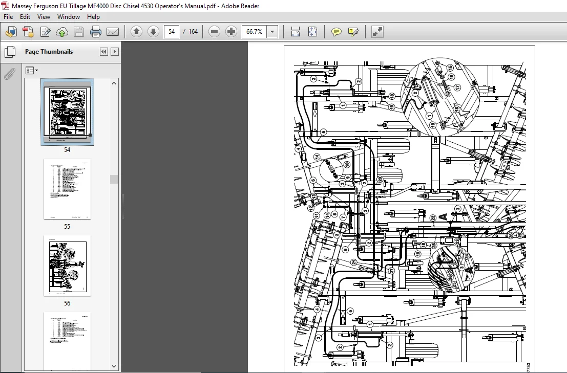
Lift Hydraulics
33/4”x16”Hydraulic CyIinder10858R
4”x16” Rephasing Cylinder t 12000R
Rigid Shear Bolt Shank
Auto Reset Shank
Individual Front Blade Assembly (Version 1, prior to 84530002400028)
Individual Front Blade Assembly (Version 2, 84530002400028 and later)
Front Gang Mounting
Rear Gang Assembly
Scraper Bar Assembly
Rear Gang Mounting
Front Gang Lift Hydraulics
Rear Gang Lift Hydraulics
31/2”x8”Hydraulic Cylinder(12061R)
31/4″x8”Hydraulic Cylinder(12065R)
33/4”x8”Hydraulic Cylinder12059R
4”x8”HydraulicCyIinder12047R
Fold Hydraulics
4”x30”Hydraulic Cylinder10812R
Front Depth Control indicator
Rear Depth Control Indicator
Light Kit Assembly
Rear Tow Hitch Assembly
Massey Ferguson Decal Placement
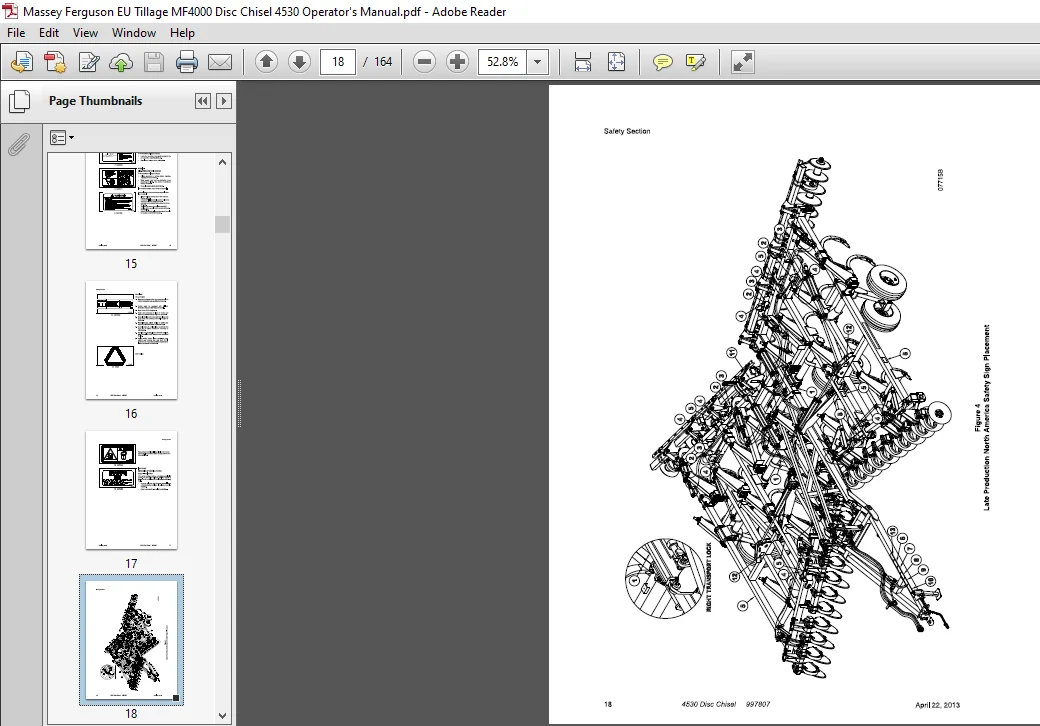
North America Safety Sign Placement
Non-North America Safety Sign Placement
Placement Section
The drawings in this section give mounting locations forvarious machine components
19 Shank Component Placement
Operating Section
Attaching To The Tractor
Initial Operating Check List
Beginning Field Operation
Jack Mounting and Storage
Hose Holder Adjustment
Hydraulic Lift System
Hydraulic Disc Gang Lifts
Leveling The Disc Chisel
Transport Locks
Depth Adjustment (machine)
Disc Gang Adjustment
Depth Adjustment (front disc gang)
Front Disc Gang Adjustment
Depth Adjustment (Rear Disc Gangs)
Rear Disc Gang Adjustment
Rigid Scraper Adjustment (Rear Gangs)
Rigid Shear Bolt Shanks
Auto Reset Shank
Storage At The End of The Season
At The Beginning of The Next Season
Lubrication
Lubrication section
The illustrations in this section Show locations of the areas needing lubricated and the frequency
147
Wheel Bearings
Tandem Pivot Bearings
Appendix section
Proper Bolt Use
SAE Fastener Torque Specifications
Recommended Minimum Machine Weights for Towing
Trouble Shooting
Trouble Shooting
Numerical Index
DESCRIPTION:
Massey Ferguson EU Tillage MF4000 Series 4530 Disc Chisel Operator’s Manual – PDF DOWNLOAD
SAFETY SECTIONS:
For your safety and to develop a better understanding at your equipment. thoroughly read the Operating Section of this manual before operation.
Safety-Alert Symbols :
The SAFE‘N-ALERT SYMBOL. as shown in Figure 1, indicates that there is a potential hazard to personal safety involved and extra safety precautions must be taken. When you see this symbol, be alert and carefully read the nota- tion that follows it. Hazard control and accident prevention are dependent upon the carefulness, awareness and proper training of the personnel involved in the operation. transport, maintenance and storage of this equipment. The words DANGER, WARNING. or CAUTION are used with the Safety-Alert Symbols. as shown in Figure 2, and are placed throughout this manual tor your personal safety. – Be sure you and your fellow workers follow them closely.
Safety Signs :
- Clean the area the sign is to be placed on.
- Spray soapy water on the surface where the sign is to be placed.
- Peel the backing from the sign. and carefully place on the wet surface. when placement is in the correct posi- tion. press firmly onto the surface.
- Squeeze out the air bubbles with the edge of a credit card.
The types of safety signs and locations on the machine are shown in the following illustrations. Good operating tech- niques require that you farnlliarize yourself with the various safety signs, the type of warning and area or particular function that requires your SAFETY AWARENESS.
IMAGES PREVIEW OF THE MANUAL:
MASSEY FERGUSON EU TILLAGE MF4000 SERIES 4530 DISC CHISEL OPERATOR’S MANUAL – PDF DOWNLOAD:
PLEASE NOTE:
- This is the SAME exact manual used by your dealers to fix your vehicle.
- The same can be yours in the next 2-3 mins as you will be directed to the download page immediately after paying for the manual.
- Any queries / doubts regarding your purchase, please feel free to contact [email protected]