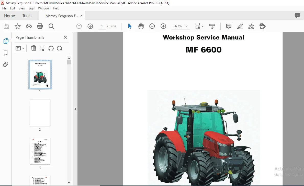
Massey Ferguson EU Tractor MF 6600 Series 6612 6613 6614 6615 6616 Service Manual – PDF DOWNLOAD
Original price was: $68.95.$31.95Current price is: $31.95.
Massey Ferguson EU Tractor MF 6600 Series 6612 6613 6614 6615 6616 Service Manual – PDF DOWNLOAD
Description
Massey Ferguson EU Tractor MF 6600 Series 6612 6613 6614 6615 6616 Service Manual – PDF DOWNLOAD
DESCRIPTION:
Massey Ferguson EU Tractor MF 6600 Series 6612 6613 6614 6615 6616 Service Manual – PDF DOWNLOAD
Using the manual:
General
The purpose of this manual is to assist Dealers and Agents in the installation, servicing and repair of Massey Ferguson equipment. It is important to follow the methods shown and to use special tools in order to perform the operations within the times stated in the repair time schedule.
Service tools:
Where the use of a service tool is necessary to carry out an operation, the tool reference is mentioned with the relevant instruction. Tool drawings for makeshift tools are given at the end of the relevant sections.
Repairs and parts replacement:
During replacement operations, it is essential that only genuine Massey Ferguson parts are used. If non-genuine Massey Ferguson parts are fitted, the tractor warranty may be invalidated and tractor safety may be compromised. All Massey Ferguson parts are guaranteed by the manufacturer. Massey Ferguson Dealers and Agents are required to supply only genuine service parts. When carrying out repairs and fitting replacement parts and accessories, the following points are of particular importance:
– Legislation in certain countries prohibits the fitting of parts that do not comply with the tractor manufacturer’s specifications
– Torque wrench setting figures given in the workshop manual must be strictly respected
– Locking devices must be fitted where specified. If the efficiency of a locking device is impaired during disassembly, it must be replaced.
TABLE OF CONTENTS:
Massey Ferguson EU Tractor MF 6600 Series 6612 6613 6614 6615 6616 Service Manual – PDF DOWNLOAD
1 Introduction
1A10 MF 6600 – General
MF 6600
1A11 MF 6600 – Error codes
1A12 MF 6600 – Fuse box, electrical diagrams, harnesses, hydraulics
diagrams and pneumatic diagrams
1A16 MF 6600 – Adjustments, bleeding and calibrations
2 Separation of assemblies
2A17 Front linkage – Removing and refitting
2B17 Front axle – Removing and refitting
2C17 Cooling unit – Removing and refitting
2D17 Front frame – Removing and refitting
2E17 Bonnet – Removing and refitting
2F17 Engine – Removing and refitting
2G17 Gearbox – Removing and refitting
2H17 Cab – Removing and refitting
2117 Pedal assembly – Removing and refitting
2J17 Rear axle – Removing and refitting
3 Engine
3A 11 Sisu Tier 4i engine – Error codes
3A12 Sisu Tier 4i engine – Electrical and hydraulics diagrams
3A 13 Sisu Tier 4i engine – Layout of components
3A14 Sisu Tier 4i engine – Tests and diagnostics
3A16 Sisu Tier 4i engine – Adjustments, bleeding and calibrations
3A 17 Sisu Tier 4i engine – Disassembly and reassembly
3B10 e3 SCR Technology engine – General
3B12 e3 SCR Technology engine – Electrical and hydraulic diagrams
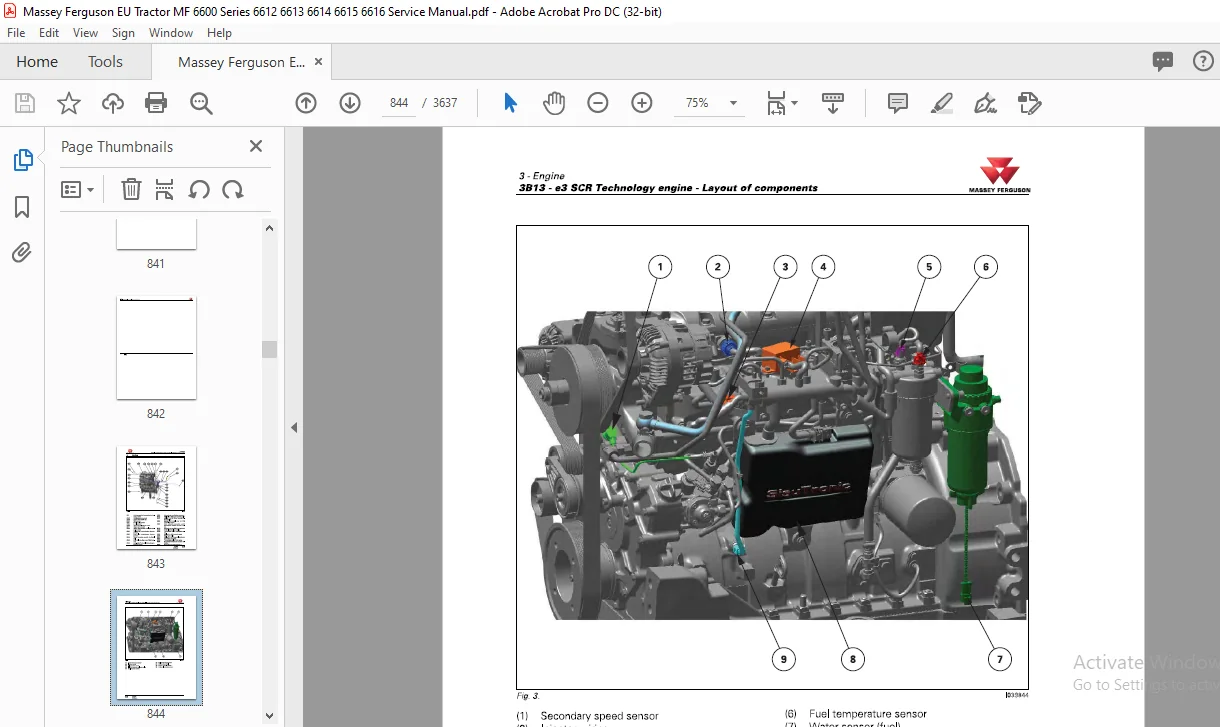
3B13 e3 SCR Technology engine – Layout of components
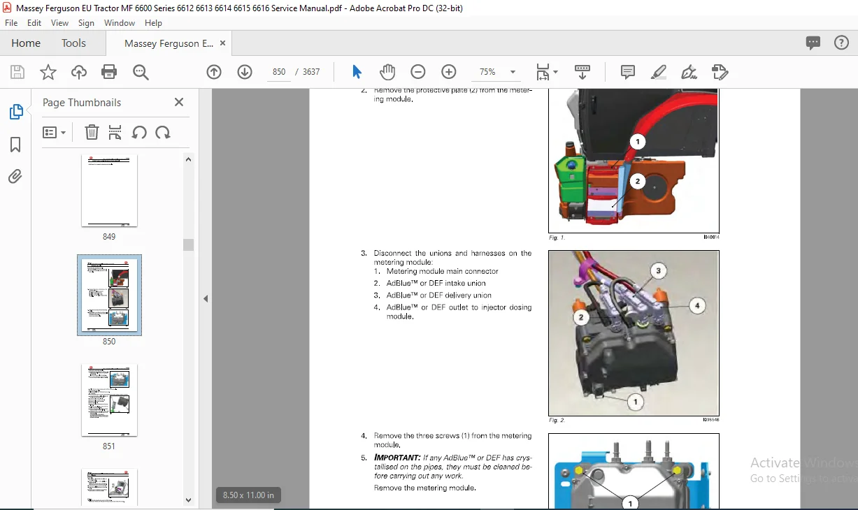
3B17 e3 SCR Technology engine – Disassembly and reassembly
3B18 e3 SCR Technology engine – Service tools
4 Clutch
Chapter intentionally left blank
5 Gearbox
5A10 ML130/ML160 – General
5A11 ML130/ML160 – Error codes
5A12 ML 130/ML 160 – Electrical and hydraulics diagrams
5A13 ML 130/ML 160- Layout of components
5A14 ML 130/ML 160 – Tests and diagnostics
5A16 ML130/ML160 – Adjustments, bleeding and calibrations
5A17 ML 130/ML 160 – Disassembly and reassembly
5A18 ML 130/ML 160 – Service tools
5C10 GBA25 – General
5C11 GBA25 – Error codes
5C13 GBA25 – Layout of components
3
MF6600
Table of contents MASSEY FERGUSON
5C16 GBA25 – Adjustments, bleeding and calibrations
5C17 GBA25 – Disassembly and reassembly
5C20 GBA25/PowerShuttle – General
5C23 GBA25/PowerShuttle – Layout of components
5C27 GBA25/PowerShuttle – Disassembly and reassembly
5C28 GBA25/PowerShuttle – Service tools
5C30 GBA25/Powershift module – General
5C33 GBA25/Powershift module – Layout of components
5C37 GBA25/Powershift module – Disassembly and reassembly
5C38 GBA25/Powershift module – Service tools
5C40 GBA25/Robotic mechanical gearbox – General
5C43 GBA25/Robotic mechanical gearbox – Layout of components
5C47 GBA25/Robotic mechanical gearbox – Disassembly and reassembly
5C48 GBA25/Robotic mechanical gearbox – Service tools
5C50 GBA25/Creeper gears – General
5C53 GBA25/Creeper gears – Layout of components
5C57 GBA25/Creeper gears – Disassembly and reassembly
5C60 GBA25/Super creeper gears – General
5C63 GBA25/Super creeper gears – Layout of components
5C67 GBA25/Super creeper gears – Disassembly and reassembly
6 Rear axle
4
6A13 HA130/160/Final drives – Layout of components
6A17 HA130/160/Final drives – Disassembly and reassembly
6A21 HA 130/160/Differential – Error codes
6A22 HA 130/160/Differential – Electrical and hydraulics diagrams
6A23 HA 130/160/Differential – Layout of components
6A26 HA 130/160/Differential – Adjustments, bleeding and calibrations
6A27 HA 130/160/Differential – Disassembly and reassembly
6A31 HA 130/160/Tractor braking – Error codes
6A32 HA130/160/Tractor braking – Electrical and hydraulics diagrams
6A33 HA 130/160/Tractor braking – Layout of components
6A36 HA 130/160/Tractor braking – Adjustments, bleeding and calibrations
6A37 HA 130/160/Tractor braking – Disassembly and reassembly
6A51 HA 130/160/Hydraulic trailer braking – Error codes
6A52 HA130/160/Hydraulic trailer braking – Electrical and hydraulics
diagrams
HA 130/160/Pneumatic trailer braking – General
HA 130/160/Pneumatic trailer braking – Electrical and hydraulics
diagrams
HA 130/160/Pneumatic trailer braking – Layout of components
HA 130/160/Pneumatic trailer braking – Tests and diagnostics
HA 130/160/Pneumatic trailer braking – Adjustments, bleeding and
calibrations
HA 130/160/Pneumatic trailer braking – Disassembly and reassembly
GPA20 – General
GPA20 – Layout of components
GPA20/Trumpet housings – General
GPA20/Trumpet housings – Layout of components
GPA20/Trumpet housings – Disassembly and reassembly
GPA20/Trumpet housings – Service tools
GPA20/Differential – General
GPA20/Differential – Layout of components
GPA20/Differential – Disassembly and reassembly
GPA20/Differential – Service tools
GPA20/Tractor braking – General
GPA20/Tractor braking – Layout of components
GPA20/Tractor braking – Adjustments, bleeding and calibrations
GPA20/Tractor braking – Disassembly and reassembly
GPA20/Tractor braking – Service tools
GPA20/Hydraulic trailer braking – General
GPA20/Hydraulic trailer braking – Layout of components
GPA20/Hydraulic trailer braking – Disassembly and reassembly
GPA20/Pneumatic trailer braking – General
GPA20/Pneumatic trailer braking – Electrical and hydraulics diagrams
GPA20/Pneumatic trailer braking – Layout of components
GPA20/Pneumatic trailer braking – Tests and diagnostics
GPA20/Pneumatic trailer braking – Adjustments, bleeding and
calibrations
GPA20/Pneumatic trailer braking – Disassembly and reassembly
GPA20/Pneumatic trailer braking – Service tools
GPA20/Hitch/Linkage – General
GPA20/Hitch/Linkage – Layout of components
GPA20/Hitch/Linkage – Adjustments, bleeding and calibrations
GPA20/Hitch/Linkage – Disassembly and reassembly
GPA20/Auto-hitch – General
GPA20/Auto-hitch – Adjustments, bleeding and calibrations
GPA20/Auto-hitch – Disassembly and reassembly
GPA20 +/Hitch/Increased capacity linkage – General
GPA20 +/Hitch/Increased capacity linkage – Layout of components
GPA20 +Hitch/Increased capacity linkage – Adjustments, bleeding
and calibrations
6D87 GPA20 +Hitch/Increased capacity linkage – Disassembly and
reassembly
6D88 GPA20 +Hitch/Increased capacity linkage – Service tools
Power take-off
7 A 11 HA 130/160/Power take-off – Error codes
7 A 12 HA 130/160/Power take-off – Electrical and hydraulics diagrams
7 A 13 HA 130/160/Power take-off – Layout of components
7 A 16 HA 130/160/Power take-off – Adjustments, bleeding and calibrations
7 A 17 HA 130/160/Power take-off – Disassembly and reassembly
7C10 GPA20 – General
7C20 GPA20/lntermediate shaft/Driving gear/PTO brake – General
7C23 GPA20/lntermediate shaft/Driving gear/PTO brake – Layout of
components
reassembly
GPA20/GSPTO – General
GPA20/GSPTO – Layout of components
GPA20/GSPTO – Disassembly and reassembly
GPA20/Removable PTO shaft – General
GPA20/Removable PTO shaft – Layout of components
GPA20/Removable PTO shaft – Disassembly and reassembly
GPA20/Shiftable PTO shaft – General
GPA20/Shiftable PTO shaft – Layout of components
GPA20/Shiftable PTO shaft – Disassembly and reassembly
GPA20/Clutch – General
GPA20/Clutch – Layout of components
GPA20/Clutch – Disassembly and reassembly
GPA20/Clutch – Service tools
GPA20/PTO electrohydraulic controls – General
GPA20/PTO electrohydraulic controls – Disassembly and reassembly
Zuidberg front power take-off – General
Zuidberg front power take-off – Layout of components
Zuidberg front power take-off – Tests and diagnostics
Zuidberg front power take-off – Adjustments, bleeding and
calibrations
7E17 Zuidberg front power take-off – Disassembly and reassembly
Front axle
8A10 DANA 735n40 – General
8A 11 DANA 735n40 – Error codes
8A 12 DANA 735n40 – Electrical and hydraulics diagrams
8A 13 DANA 735n40 – Layout of components
8A 16 DANA 735n40 – Adjustments, bleeding and calibrations
8A17 DANA 735n40 – Disassembly and reassembly
8B10 HA130/4WD clutch – General
8B12 HA130/4WD clutch – Electrical and hydraulics diagrams
8B13 HA130/4WD clutch – Layout of components
8B16 HA 130/4WD clutch – Adjustments, bleeding and calibrations
8B17 HA130/4WD clutch – Disassembly and reassembly
8B23 HA130/Universal joint shaft brake – Layout of components
8B27 HA130/Universal joint shaft brake – Disassembly and reassembly
8C10 HA130/Steering unit/Closed Centre – General
8C12 HA130/Steering unit/Closed Centre – Electrical and hydraulics
HA130/Steering unit/Closed Centre – Layout of components
HA130/Steering unit/Closed Centre – Disassembly and reassembly
GPA20/4WD clutch – General
GPA20/4WD clutch – Layout of components
GPA20/4WD clutch – Disassembly and reassembly
GPA20/Steering unit/Closed Centre – General
GPA20/Steering unit/Closed Centre – Electrical and hydraulics
diagrams
GPA20/Steering unit/Closed Centre – Layout of components
GPA20/Steering unit/Closed Centre – Disassembly and reassembly
GPA20/Steering unit/Open Centre – General
GPA20/Steering unit/Open Centre – Electrical and hydraulics
diagrams
8E23 GPA20/Steering unit/Open Centre – Layout of components
8E27 GPA20/Steering unit/Open Centre – Disassembly and reassembly
8F17 Steering rams – Disassembly and reassembly
Hydraulics
9A10 HA130/LS hydraulic system – General
9A12 HA130/LS hydraulic system – Electrical and hydraulics diagrams
9A13 HA130/LS hydraulic system – Layout of components
9A14 HA130/LS hydraulic system – Tests and diagnostics
HA130/LS hydraulic system – Disassembly and reassembly
HA 130/LS hydraulic system – Service tools
HA130/LS hydraulic system/Hydraulic pumps – General
HA130/LS hydraulic system/Hydraulic pumps – Electrical and
hydraulics diagrams
HA130/LS hydraulic system/Hydraulic pumps – Layout of
components
HA130/LS hydraulic system/Hydraulic pumps – Tests and diagnostics
HA130/LS hydraulic system/Hydraulic pumps – Disassembly and
reassembly
HA130/LS hydraulic system/Hydraulic pumps – Service tools
HA130/LS hydraulic system/Auxiliary spool valves – General
HA130/LS hydraulic system/Auxiliary spool valves – Error codes
HA130/LS hydraulic system/Auxiliary spool valves – Electrical and
hydraulics diagrams
HA130/LS hydraulic system/Auxiliary spool valves – Layout of
components
HA130/LS hydraulic system/Auxiliary spool valves – Tests and
diagnostics
HA 130/LS hydraulic system/Auxiliary spool valves – Disassembly and
reassembly
HA130/LS hydraulic system/Auxiliary spool valves – Service tools
HA130/LS hydraulic system/Rear linkage – General
HA 130/LS hydraulic system/Rear linkage – Error codes
HA130/LS hydraulic system/Rear linkage – Electrical and hydraulics
diagrams
HA130/LS hydraulic system/Rear linkage – Layout of components
HA130/LS hydraulic system/Rear linkage – Tests and diagnostics
HA130/LS hydraulic system/Rear linkage – Disassembly and
reassembly
HA130/LS hydraulic system/Rear linkage – Service tools
HA130/LS hydraulic system/Front linkage – General
HA130/LS hydraulic system/Front linkage – Electrical and hydraulics
diagrams
HA130/LS hydraulic system/Front linkage – Layout of components
HA130/LS hydraulic system/Front linkage – Tests and diagnostics
HA130/LS hydraulic system/Front linkage – Adjustments, bleeding
and calibrations
HA130/LS hydraulic system/Front linkage – Disassembly and
reassembly
HA130/LS hydraulic system/Front linkage – Service tools
GPA20/Load Sensing – General
GPA20/Load Sensing – Electrical and hydraulics diagrams
GPA20/Load Sensing – Layout of components
GPA20/Load Sensing – Tests and diagnostics
GPA20/Load Sensing – Disassembly and reassembly
GPA20/Load Sensing/Right-hand cover plate – General
GPA20/Load Sensing/Right-hand cover plate – Layout of components
GPA20/Load Sensing/Right-hand cover plate – Disassembly and
reassembly
GPA20/Load Sensing/Right-hand cover plate – Service tools
GPA20/Load Sensing/Left-hand cover plate – General
GPA20/Load Sensing/Left-hand cover plate – Layout of components
9837 GPA20/Load Sensing/Left-hand cover plate – Disassembly and
reassembly
GPA20/Load Sensing/Linkage spool valve – General
GPA20/Load Sensing/Linkage spool valve – Layout of components
GPA20/Load Sensing/Linkage spool valve – Disassembly and
reassembly
GPA20/Load Sensing/Auxiliary spool valves – General
GPA20/Load Sensing/Auxiliary spool valves – Layout of components
GPA20/Load Sensing/Auxiliary spool valves – Adjustments, bleeding
and calibrations
9857 GPA20/Load Sensing/Auxiliary spool valves – Disassembly and
reassembly
Open Centre – General
Open Centre – Electrical and hydraulics diagrams
Open Centre – Tests and diagnostics
Open Centre/Right-hand cover plate – General
Open Centre/Right-hand cover plate – Layout of components
Open Centre/Right-hand cover plate – Disassembly and reassembly
Open Centre/Left-hand cover plate – General
Open Centre/Left-hand cover plate – Layout of components
Open Centre/Left-hand cover plate – Disassembly and reassembly
100 I/min Open Centre – General
100 I/min Open Centre – Electrical and hydraulics diagrams
100 I/min Open Centre – Tests and diagnostics
100 I/min Open Centre/Right-hand cover plate – General
100 I/min Open Centre/Right-hand cover plate – Layout of
components
9D27 100 I/min Open Centre/Right-hand cover plate – Disassembly and
reassembly
100 I/min Open Centre/Left-hand cover plate – General
100 I/min Open Centre/Left-hand cover plate – Layout of components
100 I/min Open Centre/Left-hand cover plate – Disassembly and
reassembly
Open Centre/Linkage spool valve – General
Open Centre/Linkage spool valve – Layout of components
Open Centre/Linkage spool valve – Disassembly and reassembly
Open Centre/Auxiliary spool valves – General
Open Centre/Auxiliary spool valves – Layout of components
Open Centre/Auxiliary spool valves – Adjustments, bleeding and
calibrations
Open Centre/Auxiliary spool valves – Disassembly and reassembly
Open CentreNalve 21 bar (305 psi) – General
Open CentreNalve 21 bar (305 psi) – Layout of components
Open CentreNalve 21 bar (305 psi) – Adjustments, bleeding and
calibrations
9E37 Open CentreNalve 21 bar (305 psi) – Disassembly and reassembly
Electricity
10A12 Lighting and equipment – Electrical and hydraulics diagrams
10810 Fuse box – General
10812 Fuse box – Electrical and hydraulics diagrams
10C14 Alternator – Tests and diagnostics
1OC17 Alternator – Disassembly and reassembly
MASSEY FERGUSON
MF6600
Table of contents
1OC18 Alternator – Service tools
10D10 Starter – General
10D14 Starter – Tests and diagnostics
10D17 Starter – Disassembly and reassembly
10E17 Triflash triangle – Assembly
11 Electronics
11A10 MF 6600 – List of all components
12 Cab
12A10 Standard air conditioning – General
12A 12 Standard air conditioning – Electrical and hydraulics diagrams
12A13 Standard air conditioning – Layout of components
12A14 Standard air conditioning – Tests and diagnostics
12A 16 Standard air conditioning – Adjustments, bleeding and calibrations
12A17 Standard air conditioning – Disassembly and reassembly
12810 Self-regulating air conditioning – General
12811 Self-regulating air conditioning – Error codes
12812 Self-regulating air conditioning – Electrical and hydraulics diagrams
12813 Self-regulating air conditioning – Layout of components
12814 Self-regulating air conditioning – Tests and diagnostics
12816 Self-regulating air conditioning – Adjustments, bleeding and
calibrations
12817 Self-regulating air conditioning – Disassembly and reassembly
12C10 Semi-active hydraulic suspension – General
12C12 Semi-active hydraulic suspension – Electrical and hydraulics
diagrams
12C13 Semi-active hydraulic suspension – Layout of components
12C16 Semi-active hydraulic suspension – Adjustments, bleeding and
calibrations
12C17 Semi-active hydraulic suspension – Disassembly and reassembly
13 Accessories
accessories kits
14 Service tools
14A01 General
14A02 Separation of assemblies
14A03 Engine
14A05 Gearbox
14A06 Rear axle
14A07 Power take-off
14A08 Front axle
14A09 Hydraulics
14A 10 Electricity
14A11 Electronics
14A12 Cab
Customer Support: [email protected]
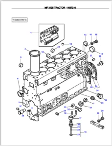
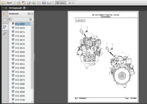
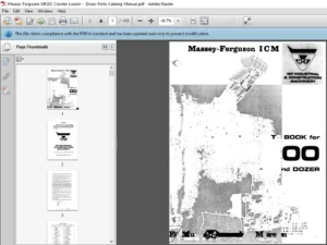
IMAGES PREVIEW OF THE MANUAL:
PLEASE NOTE:
- This is the SAME manual used by the dealers to troubleshoot any faults in your vehicle. This can be yours in 2 minutes after the payment is made.
- Contact us at [email protected] should you have any queries before your purchase or that you need any other service / repair / parts operators manual.
S.V