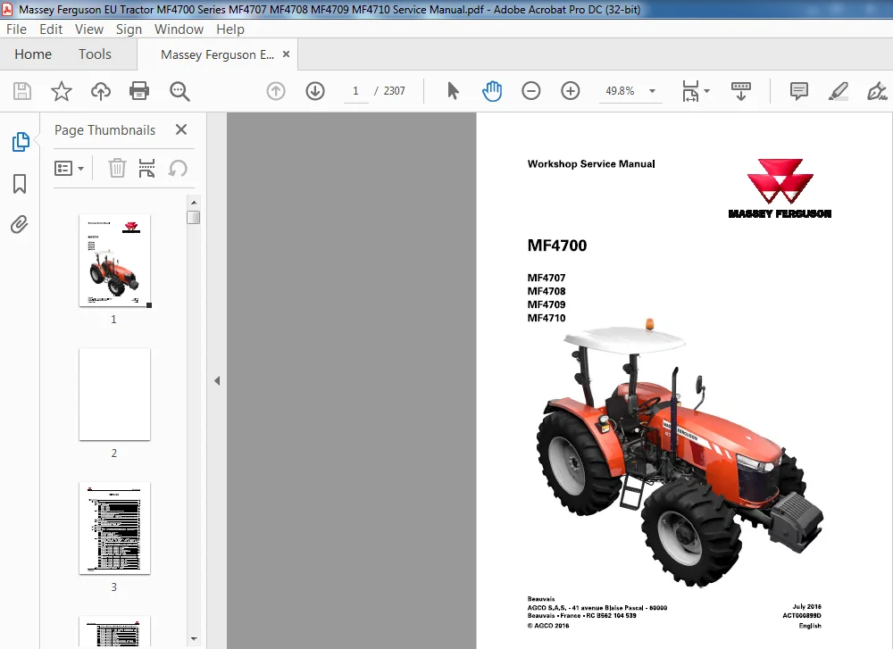
Massey Ferguson EU Tractor MF4700 Series MF4707 MF4708 MF4709 MF4710 Service Manual – PDF DOWNLOAD
Original price was: $87.95.$31.95Current price is: $31.95.
Massey Ferguson EU Tractor MF4700 Series MF4707 MF4708 MF4709 MF4710 Service Manual – PDF DOWNLOAD
Description
Massey Ferguson EU Tractor MF4700 Series MF4707 MF4708 MF4709 MF4710 Service Manual – PDF DOWNLOAD
DESCRIPTION:
Massey Ferguson EU Tractor MF4700 Series MF4707 MF4708 MF4709 MF4710 Service Manual – PDF DOWNLOAD
General
The purpose of t his manual is t o assist Dealers and A gents in the installation, servicing and repair of Massey Ferguson equipment. It is import ant t o follow t he methods show n and t o use special t ools in order t o perform t he operations within the timesst ated in t he repair time schedule.
Structure of the manual
Contents
For quick reference, each chapter starts with a table of contents, lising t he various sect ions included in that chapter
Service tools
Where t he use of a service tool is necessary t o carry out an operation, t he tool reference is mentioned w it h t he relevant instruction. Tool drawings for makeshift tools are given at t he end of t he relevant sect ions.
During replacement operations, using genuine Massey Ferguson part s is essential Fitting part s ot her t han genuine Massey Ferguson parts invalidates the tractor warrant y and tractor safety may be compromised All Massey Ferguson part s are guaranteed b y the manufacture Massey Ferguson Dealers and A gent s are required t o supply genuine part s. F or repairs and for ftiting replacement part s a nd accessories , w e draw y our att ent iont ot he following point s in particular:
• L egislat ion in cert ain count ries prohibtist he ftiting of part st hat do not comply w ti ht het ract or
manufacturer’ s specificat ions
• Torque wrench setting figures given in t he workshop manual must be strictly respected
• Locking devices must be ftit edw here specified If the efficiency of a locking device is impaired during disassembly, it must be replaced.
TABLE OF CONTENTS:
Massey Ferguson EU Tractor MF4700 Series MF4707 MF4708 MF4709 MF4710 Service Manual – PDF DOWNLOAD
1 Introduction 1-1
1 1 General 1-9
1 1 1 Using the manua l 1-9
1 1 2 General specifications 1-9
1 1 2 1 MF4707 mode l 1-9
1 1 2 2 Model MF4708 1-1 1
1 1 2 3 Model MF4709 1-1 3
1 1 2 4 Model MF47 10 1-1 5
1 1 3 Capacities and dimensions of the GTA 50 transmission 1-17
1 1 3 1 Capacities 1-17
1 1 3 2 MF 4700 /Dimensions and weights 1-1 9
1 1 3 3 Dimensions and weights 1-2 1
1 1 3 4 Attachment points for 3- cylinder engines 1-2 3
1 1 3 5 Attachment points for 4- cylinder engines for MF 4708 tractors with Tier 2 /
Stage 11 engine 1-2 5
1 1 4 Conversion table 1-2 6
1 1 5 Tightening torques 1-2 8
1 1 5 1 Tightening torques for screws and nuts 1-2 8
1 1 5 2 Tightening torques for hydraulic unions 1-3 2
1 1 6 Retaining compounds and sealing products 1-3 5
1 2 Error codes 1-37
1 2 1 Error codes 1-37
1 3 Fuse box, electrical diagrams, harnesses and hydraulics diagrams 1-42
MF4700
ACT000899D
1 3 1 Fuse box 1-4 2
1 3 1 1 Main fuse boxes: Platform models 1-4 2
1 3 1 2 Main fuse boxes: Cab models 1-70
1 3 1 3 Additional fuse boxes: Platform models 1-82
1 3 1 4 Additional fuse boxes: Cab models 1-90
1 3 1 5 Fuse boxes on the side of the battery 1-9 1
1 3 2 AGCO Power Tier2 engine, mechanical reverse shuttle , platform 1-103
1 3 2 1 AP Tier2 – Summary of electrical diagrams- Mechanical reverse shuttle 1-103
1 3 2 2 AP Tier 2 – Mechanical reverse shuttle/Electrical power supply with
battery isolator 1-1 03
1 3 2 3 AP Tier 2 – Mechanical reverse shuttle/Electrical power supply without
battery isolator 1-1 04
1 3 2 4 AP Tier 2 – Mechanical reverse shuttle/Instrument pane l 1-105
1 3 2 5 AP Tier2 – Mechanical reverse shuttle/Engine 1-106
1 3 2 6 AP Tier2 – Mechanical reverse shuttle/Linkage 1-107
1 3 2 7 AP Tier2 – Mechanical reverse shuttle/Rear power tak-e off 1-108
1 3 2 8 AP Tier2 – Mechanical reverse shuttle/Lighting 1-109
1 3 2 9 AP Tier 2 – Mechanical reverse shuttle/Lighting 2 1-1 10
1 3 2 10 AP Tier 2 – Mechanical reverse shuttle/Fenders and European trailer
connector 1-1 1 1
1 3 2 1 1 AP Tier 2 – Mechanical reverse shuttle/Fenders and North America trailer
connector 1-1 1 2
1 3 2 1 2 AP Tier2 – Mechanical reverse shuttle/Work lights 1-1 1 3
1 3 2 1 3 AP Tier2 – Mechanical reverse shuttle/Power socket 1-1 1 4
1 3 2 1 4 AP Tier2 – Mechanical reverse shuttle/Front loader 1-1 1 5
1 3 2 1 5 AP Tier2 – Mechanical reverse shuttle/Linkage console 1 -1 1 6
1 3 2 1 6 AP Tier2 – Mechanical reverse shuttle/Transmission 1-1 17
1 3 2 17 AP Tier2 – Mechanical reverse shuttle/Earth 1-1 1 8
1 3 3 AGCO Power Tier2 engine, PowerShuttle , platform 1-1 1 9
Table of contents
1 3 3 1 AP Tier 2 – Summary of electrical diagrams – Electrohydraulic reverse
shuttle 1-1 1 9
1 3 3 2 A P Tier 2 – PowerShuttle/Electrical power supply with battery isolator 1-1 20
1 3 3 3 AP Tier 2 – PowerShuttle/Electrical power supply without battery isolator 1-1 2 1
1 3 3 4 A P Tier 2 – PowerShuttle/lnstrument panel 1-1 22
1 3 3 5 AP Tier 2 – PowerShuttle/Engine 1-1 2 3
1 3 3 6 AP Tier 2 – PowerShuttle/Linkage 1-1 24
1 3 3 7 AP Tier 2 – PowerShuttle/Rear PTO 1-125
1 3 3 8 AP Tier 2 – PowerShuttle/PowerShuttle 1-1 2 6
1 3 3 9 A P Tier 2 – PowerShuttle/Lighting 1-1 27
1 3 3 10 AP Tier 2 – PowerShuttle/Lighting 2 1-1 28
1 3 3 1 1 AP Tier 2 – PowerShuttle/Fenders and European trailer connector 1-1 29
1 3 3 1 2 AP Tier 2 – PowerShuttle/Fenders and North America trailer connector 1-1 3 0
1 3 3 1 3 A P Tier 2 – PowerShuttle/Work lights 1-1 3 1
1 3 3 1 4 AP Tier 2 – PowerShuttle/Power socket 1-1 3 2
1 3 3 15 AP Tier 2 – PowerShuttle/Front loader 1 -1 3 3
1 3 3 1 6 AP Tier 2 – PowerShuttle/Linkage console 1-1 3 4
1 3 3 17 AP Tier 2 – PowerShuttle/Transmission 1-1 3 5
1 3 3 18 AP Tier 2 – PowerShuttle/Earth 1 -1 3 6
1 3 4 AGCO Power Tier 3 engine, mechanical reverse shuttle, platform 1-1 3 7
1 3 4 1 AGCO Power Tier 3 – Mechanical reverse shuttle/Summary 1-1 3 7
1 3 4 2 AGCO Power Tier 3 – Mechanical reverse shuttle/Electrical power supply
with battery isolator 1-1 3 9
1 3 4 3 AGCO Power Tier 3 – Mechanical reverse shuttle/Electrical power supply
without battery isolator 1-1 3 9
1 3 4 4 AGCO Power Tier 3 – Mechanical reverse shuttle/Instrument panel 1-1 40
1 3 4 5 AGCO Power Tier 3 – Mechanical reverse shuttle/Engine 1-1 4 1
1 3 4 6 AGCO Power Tier 3 – Mechanical reverse shuttle/Engine 2 1-1 42
1 3 4 7 AGCO Power Tier 3 – Mechanical reverse shuttle/Linkage 1-1 4 3
1 3 4 8 AGCO Power Tier 3 – Mechanical reverse shuttle/Rear PTO 1-1 4 4
1 3 4 9 AGCO Power Tier 3 – Mechanical reverse shuttle/PowerShuttle 1-1 45
1 3 4 10 AGCO Power Tier 3 – Mechanical reverse shuttle/PowerShuttle 2 1-1 46
1 3 4 1 1 AGCO Power Tier 3 – Mechanical reverse shuttle/Lighting 1-1 47
1 3 4 1 2 AGCO Power Tier 3 – Mechanical reverse shuttle/Lighting 2 (ISO) 1-1 48
1 3 4 1 3 AGCO Power Tier 3 – Mechanical reverse shuttle/Lighting 2 (SAE) 1-1 49
1 3 4 1 4 AGCO Power Tier 3 – Mechanical reverse shuttle/Trailer connector (ISO)
1-150
1 3 4 15 AGCO Power Tier 3 – Mechanical reverse shuttle/Trailer connector (SAE)
1-1 5 1
1 3 4 1 6 AGCO Power Tier 3 – Mechanical reverse shuttle/Work lights 1-1 5 2
1 3 4 17 AGCO Power Tier 3 – Mechanical reverse shuttle/Power socket (ISO) 1-1 5 3
1 3 4 1 8 AGCO Power Tier 3 – Mechanical reverse shuttle/Power socket (SAE) 1-1 5 4
1 3 4 1 9 AGCO Power Tier 3 – Mechanical reverse shuttle/Front loader 1-1 55
1 3 4 20 AGCO Power Tier 3 – Mechanical reverse shuttle/Linkage console 1-1 5 6
1 3 4 2 1 AGCO Power Tier 3 – Mechanical reverse shuttle/Transmission 1-157
1 3 4 22 AGCO Power Tier 3 – Mechanical reverse shuttle/Transmission 2 1-1 5 8
1 3 4 2 3 AGCO Power Tier 3 – Mechanical reverse shuttle/Earth 1-1 59
1 3 5 AGCO Power Tier 3 engine, PowerShuttle, platform 1-1 60
1 3 5 1 AGCO Power Tier 3 – PowerShuttle/Summary 1-1 60
1 3 5 2 AGCO Power Tier 3 – PowerShuttle/Electrical power supply without
battery isolator 1-1 6 2
1 3 5 3 AGCO Power Tier 3 – PowerShuttle/Electrical power supply with battery
isolator 1-1 6 2
1 3 5 4 AGCO Power Tier 3 – PowerShuttle/lnstrument panel 1-1 6 3
1 3 5 5 AGCO Power Tier 3 – PowerShuttle/Engine 1-1 6 4
1 3 5 6 AGCO Power Tier 3 – Mechanical reverse shuttle/Engine 2 1-1 65
1 3 5 7 AGCO Power Tier 3 – PowerShuttle/Linkage 1-1 6 6
1 3 5 8 AGCO Power Tier 3 – PowerShuttle/Rear PTO 1-1 67
MF4700
ACT000899D
MF4700
ACT000899D
Table of contents
1 3 5 9 AGCO Power Tier 3 – PowerShuttle/PowerShuttle 1-1 6 8
1 3 5 10 AGCO Power Tier 3 – PowerShuttle/PowerShuttle 2 1-1 69
1 3 5 1 1 AGCO Power Tier 3 – PowerShuttle/Lighting 1-170
1 3 5 1 2 AGCO Power Tier 3 – PowerShuttle/Lighting 2 (ISO) 1-17 1
1 3 5 1 3 AGCO Power Tier 3 – PowerShuttle/Lighting 2 (SAE) 1-172
1 3 5 1 4 AGCO Power Tier 3 – PowerShuttle/Trailer connector (ISO) 1-17 3
1 3 5 15 AGCO Power Tier 3 – PowerShuttle/Trailer connector (SAE) 1-17 4
1 3 5 1 6 AGCO Power Tier 3 – PowerShuttle/Work lights 1-175
1 3 5 17 AGCO Power Tier 3 – PowerShuttle/Power socket (ISO) 1-176
1 3 5 1 8 AGCO Power Tier 3 – PowerShuttle/Power socket (SAE) 1-177
1 3 5 1 9 AGCO Power Tier 3 – PowerShuttle/Front loader 1-178
1 3 5 20 AGCO Power Tier 3 – PowerShuttle/Linkage console 1-179
1 3 5 2 1 AGCO Power Tier 3 – PowerShuttle/Transmission 1-1 80
1 3 5 22 AGCO Power Tier 3 – PowerShuttle/Transmission 2 1-1 8 1
1 3 5 2 3 AGCO Power Tier 3 – PowerShuttle/Earth 1-1 82
1 3 6 AGCO Power Tier 4i engine, mechanical reverse shuttle, platform 1-1 8 3
1 3 6 1 AP Tier 4i – Mechanical reverse shuttle/Summary 1-1 8 3
1 3 6 2 AP Tier 4 i – Mechanical reverse shuttle/Electrical power supply with
battery isolator 1-1 84
1 3 6 3 AP Tier 4 i – Mechanical reverse shuttle/Electrical power supply without
battery isolator 1-1 85
1 3 6 4 AP Tier 4i – Mechanical reverse shuttle/Instrument panel 1-1 86
1 3 6 5 AP Tier 4i – Mechanical reverse shuttle/Engine 1-1 87
1 3 6 6 AP Tier 4i – Mechanical reverse shuttle/Linkage 1-1 88
1 3 6 7 AP Tier 4i – Mechanical reverse shuttle/Rear power take-off 1-189
1 3 6 8 AP Tier 4i – Mechanical reverse shuttle/PowerShuttle 1-1 90
1 3 6 9 AP Tier 4i – Mechanical reverse shuttle/Lighting 1-1 9 1
1 3 6 10 A P Tier 4i – Mechanical reverse shuttle/Lighting 2 1-192
1 3 6 1 1 AP Tier 4i – Mechanical reverse shuttle/Lighting 3 1-1 9 3
1 3 6 1 2 AP Tier 4i – Mechanical reverse shuttle/Fenders and ISO trailer
connector 1-1 9 4
1 3 6 1 3 A P Tier 4i – Mechanical reverse shuttle/Fenders and SAE trailer
connector 1-1 95
1 3 6 1 4 AP Tier 4i – Mechanical reverse shuttle/Work light 1 -196
1 3 6 15 AP Tier 4i – Mechanical reverse shuttle/ISO current socket 1-1 97
1 3 6 1 6 AP Tier 4i – Mechanical reverse shuttle/SAE current socket 1-198
1 3 6 17 AP Tier 4i – Mechanical shuttle/Front loader 1-1 99
1 3 6 1 8 AP Tier 4i – Mechanical shuttle/Linkage console 1-200
1 3 6 1 9 AP Tier 4i – Mechanical shuttle/Extension 1-20 1
1 3 6 20 AP Tier 4i – Mechanical shuttle/Earth 1-202
1 3 7 AGCO Power Tier 4i engine, PowerShuttle, platform 1-20 3
1 3 7 1 AP Tier 4i – PowerShuttle/Summary 1-203
1 3 7 2 AP Tier 4i – PowerShuttle/Electrical power supply with battery isolator 1-20 4
1 3 7 3 AP Tier 4i – PowerShuttle/Electrical power supply without battery isolator 1-205
1 3 7 4 AP Tier 4i – PowerShuttle/lnstrument panel 1-206
1 3 7 5 AP Tier 4i – PowerShuttle/Engine 1-207
1 3 7 6 AP Tier 4i – PowerShuttle/Linkage 1-208
1 3 7 7 AP Tier 4i – PowerShuttle/Rear PTO 1-209
1 3 7 8 AP Tier 4i – PowerShuttle/PowerShuttle 1-210
1 3 7 9 AP Tier 4i – PowerShuttle/Lighting 1-2 1 1
1 3 7 10 AP Tier 4 i – PowerShuttle/Lighting 2 1-2 1 2
1 3 7 1 1 AP Tier 4 i – PowerShuttle/Lighting 3 1-2 1 3
1 3 7 12 AP Tier 4i -PowerShuttle/Fenders and ISO trailer connector 1-21 4
1 3 7 1 3 AP Tier 4i -PowerShuttle/Fenders and SAE trailer connector 1-215
1 3 7 1 4 A P Tier 4i – PowerShuttle/Work light 1-2 1 6
1 3 7 15 AP Tier 4i – PowerShuttle/lSO power socket 1-217
1 3 7 1 6 AP Tier 4i – PowerShuttle/SAE power socket 1-2 1 8
1 3 7 17 AP Tier 4i – PowerShuttle/Front loader 1-2 1 9
Table of contents
1 3 7 18 AP Tier 4i – PowerShuttle/Linkage console 1-220
1 3 7 19 AP Tier 4i – PowerShuttle/Extension 1-22 1
1 3 7 20 AP Tier 4i – PowerShuttle/Earth 1-222
1 3 8 AGCO Power Tier 4F engine, mechanical reverse shuttle, platform 1-22 3
1 3 8 1 AP Tier 4F – Summary of electrical diagrams – Mechanical reverse
shuttle 1-22 3
1 3 8 2 AP Tier 4F – Mechanical shuttle/Electrical power supply with battery
isolator 1-22 4
1 3 8 3 AP Tier 4F – Mechanical shuttle/Electrical power supply without battery
isolator 1-225
1 3 8 4 AP Tier 4F – Mechanical shuttle/Instrument panel 1-226
1 3 8 5 AP Tier 4F – Mechanical shuttle/Engine 1-227
1 3 8 6 AP Tier 4F – Mechanical shuttle/Engine 2 1-228
1 3 8 7 AP Tier 4F – Mechanical shuttle/Engine 3 1-229
1 3 8 8 AP Tier 4F – Mechanical shuttle/Linkage 1-2 3 0
1 3 8 9 A P Tier 4 F – Mechanical shuttle/PTO 1-2 3 1
1 3 8 10 AP Tier 4F – Mechanical shuttle/Lighting 1-2 3 2
1 3 8 1 1 AP Tier 4F – Mechanical shuttle/Lighting 2 1-2 3 3
1 3 8 1 2 AP Tier 4F – Mechanical shuttle/Lighting 3 1-2 3 4
1 3 8 1 3 AP Tier 4F – Mechanical shuttle/ISO trailer connector 1-2 3 5
1 3 8 1 4 AP Tier 4 F – Mechanical shuttle/SAE trailer connector 1-2 3 6
1 3 8 15 AP Tier 4F – Mechanical shuttle/Work lights 1-2 3 7
1 3 8 1 6 A P Tier 4 F – Mechanical shuttle/ISO connector 1-2 3 8
1 3 8 17 AP Tier 4F – Mechanical shuttle/SAE connector 1 -239
1 3 8 1 8 AP Tier 4 F – Mechanical shuttle/Front loader 1-240
1 3 8 1 9 AP Tier 4F – Mechanical shuttle/Electronic linkage console 1-24 1
1 3 8 20 AP Tier 4F – Mechanical shuttle/Extension 1-242
1 3 8 2 1 AP Tier 4F – Mechanical shuttle/Extension 1-24 3
1 3 9 AGCO Power Tier 4F engine, PowerShuttle, platform 1-24 4
1 3 9 1 AP Tier 4F – Summary of electrical diagrams – PowerShuttle 1-24 4
1 3 9 2 AP Tier 4F – PowerShuttle/Electrical power supply with battery isolator 1-245
1 3 9 3 AP Tier 4F – PowerShuttle/Electrical power supply without battery isolator
1-246
1 3 9 4 AP Tier 4F – PowerShuttle/lnstrument panel 1-247
1 3 9 5 AP Tier 4F – PowerShuttle/Engine 1-248
1 3 9 6 AP Tier 4F – PowerShuttle/Engine 2 1-249
1 3 9 7 AP Tier 4F – PowerShuttle/Engine 3 1-250
1 3 9 8 AP Tier 4F – PowerShuttle/Linkage 1-25 1
1 3 9 9 AP Tier 4F – PowerShuttle/Rear PTO 1-25 2
1 3 9 10 AP Tier 4F – PowerShuttle/PowerShuttle 1-25 3
1 3 9 1 1 AP Tier 4F – PowerShuttle/Lighting 1 -25 4
1 3 9 1 2 AP Tier 4F – PowerShuttle/Lighting 2 1-255
1 3 9 1 3 AP Tier 4F – PowerShuttle/Lighting 3 1-25 6
1 3 9 1 4 AP Tier 4F – PowerShuttle/Trailer connector 1-257
1 3 9 15 AP Tier 4F – PowerShuttle/SAE trailer connector 1-258
1 3 9 1 6 AP Tier 4F – PowerShuttle/Work lights 1-259
1 3 9 17 AP Tier 4F – PowerShuttle/lSO connector 1-260
1 3 9 1 8 AP Tier 4F – PowerShuttle/SAE connector 1-26 1
1 3 9 1 9 AP Tier 4F – PowerShuttle/Front loader 1-26 2
1 3 9 20 AP Tier 4F – PowerShuttle/Hybrid console 1-26 3
1 3 9 2 1 AP Tier 4F – PowerShuttle/Extension 1-26 4
1 3 9 22 AP Tier 4F – PowerShuttle/Earth 1-265
1 3 10 AGCO Power Tier 3 engine, mechanical reverse shuttle, cab 1-26 6
1 3 10 1 AGCO Power Tier 3 – Cab version – Mechanical reverse shuttle/Summary
1-2 6 6
1 3 10 2 AGCO Power Tier 3 – Cab version – Mechanical reverse shuttle/Electrical
power supply without battery isolator 1-26 8
MF4700
ACT000899D
MF4700
ACT000899D
Table of contents
1 3 10 3 AGCO Power Tier 3 – Cab version – Mechanical reverse shuttle/Electrical
power supply with battery isolator 1-269
1 3 10 4 AGCO Power Tier 3 – Cab version – Mechanical reverse shuttle/Electrical
power supply 2 1-269
1 3 10 5 AGCO Power Tier 3 – Cab version – Mechanical reverse shuttle/
Instrument panel 1-270
1 3 10 6 AGCO Power Tier 3 – Cab version – Mechanical reverse shuttle/Cab 1-27 1
1 3 10 7 AGCO Power Tier 3 – Cab version – Mechanical reverse shuttle/Roof 1-272
1 3 10 8 AGCO Power Tier 3 – Cab version – Mechanical reverse shuttle/Engine 1-27 3
1 3 10 9 AGCO Power Tier 3 – Cab version – Mechanical reverse shuttle/Engine 2
1-27 4
1 3 10 10 AGCO Power Tier 3 – Cab version – Mechanical reverse shuttle/Linkage
1-275
1 3 10 1 1 AGCO Power Tier 3 – Cab version – Mechanical reverse shuttle/Rear
PTO 1-276
1 3 10 1 2 AGCO Power Tier 3 – Cab version – Mechanical reverse shuttle/
PowerShuttle 1-277
1 3 10 1 3 AGCO Power Tier 3 – Cab version – Mechanical reverse shuttle/Lighting
1-278
1 3 10 1 4 AGCO Power Tier 3 – Cab version – Mechanical reverse shuttle/Lighting
2 (ISO) 1-279
1 3 10 1 5 AGCO Power Tier 3 – Cab version – Mechanical reverse shuttle/Lighting
2 (SAE) 1-280
1 3 10 1 6 AGCO Power Tier 3 – Cab version – Mechanical reverse shuttle/Trailer
connector (ISO) 1-28 1
1 3 10 17 AGCO Power Tier 3 – Cab version – Mechanical reverse shuttle/Trailer
connector (SAE) 1-282
1 3 10 1 8 AGCO Power Tier 3 – Cab version – Mechanical reverse shuttle/Work
I ights 1-28 3
1 3 10 1 9 AGCO Power Tier 3 – Cab version – Mechanical reverse shuttle/
Connector (ISO) 1-284
1 3 10 20 AGCO Power Tier 3 – Cab version – Mechanical reverse shuttle/
Connector (SAE) 1-285
1 3 10 21 AGCO Power Tier 3 – Cab version – Mechanical reverse shuttle/
Transmission 1-286
1 3 10 22 AGCO Power Tier 3 – Cab version – Mechanical reverse shuttle/
Transmission 2 1-287
1 3 10 23 AGCO Power Tier 3 – Cab version – Mechanical reverse shuttle/Earth 1-288
1 3 1 1 AGCO Power Tier 3 engine, PowerShuttle, cab 1-289
1 3 1 1 1 AGCO Power Tier 3 – Cab version – PowerShuttle/Summary 1-289
1 3 1 1 2 AGCO Power Tier 3 – Cab version – PowerShuttle/Electrical power
supply without battery isolator 1-29 1
1 3 1 1 3 AGCO Power Tier 3 – Cab version – PowerShuttle/Electrical power
supply with battery isolator 1-29 1
1 3 1 1 4 AGCO Power Tier 3 – Cab version – PowerShuttle/Electrical power
supply 2 1-292
1 3 1 1 5 AGCO Power Tier 3 – Cab version – PowerShuttle/lnstrument panel 1-29 3
1 3 1 1 6 AGCO Power Tier 3 – Cab version – PowerShuttle/Cab 1- 294
1 3 1 1 7 AGCO Power Tier 3 – Cab version – PowerShuttle/Roof 1-295
1 3 1 1 8 AGCO Power Tier 3 – Cab version – PowerShuttle/Engine 1-296
1 3 1 1 9 AGCO Power Tier 3 – Cab version – PowerShuttle/Engine 1-297
1 3 1 1 10 AGCO Power Tier 3 – Cab version – PowerShuttle/Linkage 1-298
1 3 1 1 1 1 AGCO Power Tier 3 – Cab version – PowerShuttle/Rear PTO 1-299
1 3 1 1 1 2 AGCO Power Tier 3 – Cab version – PowerShuttle/PowerShuttle 1-300
1 3 1 1 1 3 AGCO Power Tier 3 – Cab version – PowerShuttle/Lighting 1-3 0 1
1 3 1 1 1 4 AGCO Power Tier 3 – Cab version – PowerShuttle/Lighting 2 (ISO) 1-302
1 3 1 1 15 AGCO Power Tier 3 – Cab version – PowerShuttle/Lighting 2 (SAE) 1-3 0 3
Table of contents
1 3 1 1 1 6 AGCO Power Tier 3 – Cab version – PowerShuttle/f railer connector
(ISO) 1-30 4
1 3 1 1 17 AGCO Power Tier 3 – Cab version – PowerShuttle/f railer connector
(SAE) 1-305
1 3 1 1 1 8 AGCO Power Tier 3 – Cab version – PowerShuttle/Work lights 1-306
1 3 1 1 1 9 AGCO Power Tier 3 – Cab version – PowerShuttle/Connector (ISO) 1-307
1 3 1 1 20 AGCO Power Tier 3 – Cab version – PowerShuttle/Connector (SAE) 1-308
1 3 1 1 2 1 AGCO Power Tier 3 – Cab version – PowerShuttle{fransmission 1-309
1 3 1 1 22 AGCO Power Tier 3 – Cab version – PowerShuttle{f ransmission 2 1-3 10
1 3 1 1 2 3 AGCO Power Tier 3 – Cab version – PowerShuttle/Earth 1-3 1 1
1 3 1 2 AGCO Power Tier 4 i engine, mechanical reverse shuttle, cab 1-3 1 2
1 3 1 2 1 AGCO Power Tier 4 i – Cab version – Mechanical reverse shuttle/
Summary 1-3 1 2
1 3 1 2 2 AGCO Power Tier 4 i – Cab version – Mechanical reverse shuttle/Electrical
power supply with battery isolator 1-3 1 4
1 3 1 2 3 AGCO Power Tier 4i – Cab version – Mechanical reverse shuttle/Electrical
power supply without battery isolator 1-3 1 5
1 3 1 2 4 AGCO Power Tier 4i – Cab version – Mechanical reverse shuttle/Electrical
power supply 2 1-3 1 5
1 3 1 2 5 AGCO Power Tier 4i – Cab version – Mechanical reverse shuttle/
Instrument panel 1-3 1 6
1 3 1 2 6 AGCO Power Tier 4 i – Cab version – Mechanical reverse shuttle/Cab 1-3 17
1 3 1 2 7 AGCO Power Tier 4i – Cab version – Mechanical reverse shuttle/Roof 1-3 1 8
1 3 1 2 8 AGCO Power Tier 4 i – Cab version – Mechanical reverse shuttle/Engine 1-3 1 9
1 3 1 2 9 AGCO Power Tier 4i – Cab version – Mechanical reverse shuttle/Engine 2
1-3 20
1 3 1 2 10 AGCO Power Tier 4i – Cab version – Mechanical reverse shuttle/Linkage
1-3 2 1
1 3 1 2 1 1 AGCO Power Tier 4i – Cab version – Mechanical reverse shuttle/Rear
PTO 1-3 22
1 3 1 2 1 2 AGCO Power Tier 4i – Cab version – Mechanical reverse shuttle/
PowerShuttle 1-3 2 3
1 3 1 2 1 3 AGCO Power Tier 4i – Cab version – Mechanical reverse shuttle/
Lighting 1-3 24
1 3 1 2 1 4 AGCO Power Tier 4i – Cab version – Mechanical reverse shuttle/
Lighting 2 (ISO) 1-3 25
1 3 1 2 15 AGCO Power Tier 4i – Cab version – Mechanical reverse shuttle/
Lighting 2 (SAE) 1-3 26
1 3 1 2 1 6 AGCO Power Tier 4i – Cab version – Mechanical reverse shuttle/frailer
connector (ISO) 1-3 27
1 3 1 2 17 AGCO Power Tier 4i – Cab version – Mechanical reverse shuttle/frailer
connector (SAE) 1-3 28
1 3 1 2 1 8 AGCO Power Tier 4i – Cab version – Mechanical reverse shuttle/Work
lights 1-3 29
1 3 1 2 1 9 AGCO Power Tier 4 i – Cab version – Mechanical reverse shuttle/Power
socket (ISO) 1-3 30
1 3 1 2 20 AGCO Power Tier 4i – Cab version – Mechanical reverse shuttle/Power
socket (SAE) 1-3 3 1
1 3 1 2 2 1 AGCO Power Tier 4i – Cab version – Mechanical reverse shuttle/
Transmission 1-3 3 2
1 3 1 2 22 AGCO Power Tier 4i – Cab version – Mechanical reverse shuttle/
Transmission 2 1-3 3 3
1 3 1 2 2 3 AGCO Power Tier 4i – Cab version – Mechanical reverse shuttle/Earth 1-3 3 4
1 3 1 3 AGCO Power Tier 4 i engine, PowerShuttle, cab 1-3 3 5
1 3 1 3 1 AGCO Power Tier 4 i – Cab version – PowerShuttle/Summary 1-3 3 5
1 3 1 3 2 AGCO Power Tier 4i – Cab version – PowerShuttle/Electrical power
supply with battery isolator 1-3 3 7
MF4700
ACT000899D
MF4700
ACT000899D
Table of contents
1 3 1 3 3 AGCO Power Tier 4i – Cab version – PowerShuttle/Electrical power
supply without battery isolator 1-3 37
1 3 1 3 4 AGCO Power Tier 4i – Cab version – PowerShuttle/Electrical power
supply 2 1-3 3 8
1 3 1 3 5 AGCO Power Tier 4 i- Cab version – PowerShuttle/lnstrument panel 1-3 39
1 3 1 3 6 AGCO Power Tier 4 i – Cab version – PowerShuttle/Cab 1-3 40
1 3 1 3 7 AGCO Power Tier 4i – Cab version – PowerShuttle/Roof 1 -3 4 1
1 3 1 3 8 AGCO Power Tier 4 i – Cab version – PowerShuttle/Engine 1-3 42
1 3 1 3 9 AGCO Power Tier 4i – Cab version – PowerShuttle/Engine 2 1-3 4 3
1 3 1 3 10 AGCO Power Tier 4 i- Cab version – PowerShuttle/Linkage 1-3 4 4
1 3 1 3 1 1 AGCO Power Tier 4i – Cab version – PowerShuttle/Rear PTO 1-3 45
1 3 1 3 1 2 AGCO Power Tier 4i – Cab version – PowerShuttle/PowerShuttle 1-3 46
1 3 1 3 1 3 AGCO Power Tier 4i – Cab version – PowerShuttle/Lighting 1-3 47
1 3 1 3 1 4 AGCO Power Tier 4i – Cab version – PowerShuttle/Lighting 2 (ISO) 1-3 48
1 3 1 3 15 AGCO Power Tier 4i – Cab version – PowerShuttle/Lighting 2 (SAE) 1-3 49
1 3 1 3 1 6 AGCO Power Tier 4i – Cab version – PowerShuttle/Trailer connector
(ISO) 1-3 50
1 3 1 3 17 AGCO Power Tier 4i – Cab version – PowerShuttle/Trailer connector
(SAE) 1-3 5 1
1 3 1 3 1 8 AGCO Power Tier 4i – Cab version – PowerShuttleNVork lights 1-3 5 2
1 3 1 3 1 9 AGCO Power Tier 4i – Cab version – PowerShuttle/Power socket (ISO) 1-3 5 3
1 3 1 3 20 AGCO Power Tier 4i – Cab version – PowerShuttle/Power socket (SAE) 1-3 5 4
1 3 1 3 2 1 AGCO Power Tier 4i – Cab version – PowerShuttle/Transmission 1-3 55
1 3 1 3 22 AGCO Power Tier 4i – Cab version – PowerShuttle/T ransmission 2 1-3 5 6
1 3 1 3 2 3 AGCO Power Tier 4i – Cab version – PowerShuttle/Earth 1-3 57
1 3 1 4 AGCO Power Tier 4F engine, mechanical reverse shuttle, cab 1-3 5 8
1 3 1 4 1 AGCO Power Tier 4 F – Cab version – Mechanical reverse shuttle/
Summary 1-3 5 8
1 3 1 4 2 AGCO Power Tier 4 F – Cab version – Mechanical reverse shuttle/
Electrical power supply with battery isolator 1-3 60
1 3 1 4 3 AGCO Power Tier 4F – Cab version – Mechanical reverse shuttle/
Electrical power supply without battery isolator 1-3 6 1
1 3 1 4 4 AGCO Power Tier 4F – Cab version – Mechanical reverse shuttle/
Electrical power supply 2 1 -3 62
1 3 1 4 5 AGCO Power Tier 4 F – Cab version – Mechanical reverse shuttle/
Instrument panel 1-3 6 3
1 3 1 4 6 AGCO Power Tier 4F – Cab version – Mechanical reverse shuttle/Cab 1-3 6 4
1 3 1 4 7 AGCO Power Tier 4F – Cab version – Mechanical reverse shuttle/Roof 1-3 65
1 3 1 4 8 AGCO Power Tier 4F – Cab version – Mechanical reverse shuttle/Engine 1-3 6 6
1 3 1 4 9 AGCO Power Tier 4 F – Cab version – Mechanical reverse shuttle/Engine
2 1-3 67
1 3 1 4 10 AGCO Power Tier 4F – Cab version – Mechanical reverse shuttle/Engine
3 1-3 6 8
1 3 1 4 1 1 AGCO Power Tier 4F – Cab version – Mechanical reverse shuttle/
Linkage 1-3 69
1 3 1 4 1 2 AGCO Power Tier 4F – Cab version – Mechanical reverse shuttle/Rear
PTO 1-370
1 3 1 4 1 3 AGCO Power Tier 4F – Cab version – Mechanical reverse shuttle/
PowerShuttle 1-37 1
1 3 1 4 1 4 AGCO Power Tier 4F – Cab version – Mechanical reverse shuttle/
Lighting 1-372
1 3 1 4 1 5 AGCO Power Tier 4F – Cab version – Mechanical reverse shuttle/
Lighting 2 (ISO) 1-37 3
1 3 1 4 1 6 AGCO Power Tier 4F – Cab version – Mechanical reverse shuttle/
Lighting 2 (SAE) 1-3 7 4
1 3 1 4 17 AGCO Power Tier 4 F – Cab version – Mechanical reverse shuttle/Trailer
connector (ISO) 1-375
Table of contents
1 3 1 4 1 8 AGCO Power Tier 4F – Cab version – Mechanical reverse shuttle/frailer
connector (SAE) 1-376
1 3 1 4 1 9 AGCO Power Tier 4F – Cab version – Mechanical reverse shuttle/Work
lights 1-377
1 3 1 4 20 AGCO Power Tier 4F – Cab version – Mechanical reverse shuttle/Power
socket (ISO) 1-378
1 3 1 4 2 1 AGCO Power Tier 4F – Cab version – Mechanical reverse shuttle/Power
socket (SAE) 1-379
1 3 1 4 22 AGCO Power Tier 4F – Cab version – Mechanical reverse shuttle/
Transmission 1-3 80
1 3 1 4 2 3 AGCO Power Tier 4F – Cab version – Mechanical reverse shuttle/
Transmission 2 1-3 8 1
1 3 1 4 24 AGCO Power Tier 4 F – Cab version – Mechanical reverse shuttle/Earth 1-3 82
1 3 15 AGCO Power Tier 4F engine, PowerShuttle, cab 1-3 8 3
1 3 15 1 AGCO Power Tier 4 F – Cab version – PowerShuttle/Summary 1-3 8 3
1 3 15 2 AGCO Power Tier 4F – Cab version – PowerShuttle/Electrical power
supply with battery isolator 1-3 85
1 3 15 3 AGCO Power Tier 4F – Cab version – PowerShuttle/Electrical power
supply without battery isolator 1-3 85
1 3 15 4 AGCO Power Tier 4F – Cab version – PowerShuttle/Electrical power
supply 2 1-3 86
1 3 1 5 5 AGCO Power Tier 4F – Cab version – PowerShuttle/lnstrument panel 1-3 87
1 3 1 5 6 AGCO Power Tier 4F – Cab version – PowerShuttle/Cab 1-3 88
1 3 15 7 AGCO Power Tier 4F – Cab version – PowerShuttle/Roof 1-3 89
1 3 1 5 8 AGCO Power Tier 4F – Cab version – PowerShuttle/Engine 1-3 90
1 3 15 9 AGCO Power Tier 4F – Cab version – Mechanical reverse shuttle/Engine
2 1-3 9 1
1 3 15 10 AGCO Power Tier 4 F – Cab version – PowerShuttle/Engine 3 1-3 92
1 3 15 1 1 AGCO Power Tier 4F – Cab version – PowerShuttle/Linkage 1-3 9 3
1 3 15 1 2 AGCO Power Tier 4F – Cab version – PowerShuttle/Rear PTO 1-3 9 4
1 3 15 1 3 AGCO Power Tier 4 F – Cab version – PowerShuttle/PowerShuttle 1-3 95
1 3 15 1 4 AGCO Power Tier 4F – Cab version – PowerShuttle/Lighting 1-3 96
1 3 15 15 AGCO Power Tier 4F – Cab version – PowerShuttle/Lighting 2 (ISO) 1-3 97
1 3 15 1 6 AGCO Power Tier 4F – Cab version – PowerShuttle/Lighting 2 (SAE) 1-3 98
1 3 15 17 AGCO Power Tier 4F – Cab version – PowerShuttle/f railer connector
(ISO) 1-3 99
1 3 15 1 8 AGCO Power Tier 4F – Cab version – PowerShuttle/f railer connector
(SAE) 1-400
1 3 15 1 9 AGCO Power Tier 4F – Cab version – PowerShuttle/Work lights 1-40 1
1 3 15 20 AGCO Power Tier 4F – Cab version – PowerShuttle/Power socket (ISO) 1-402
1 3 1 5 2 1 AGCO Power Tier 4F – Cab version – PowerShuttle/Power socket (SAE)
1-40 3
1 3 1 5 22 AGCO Power Tier 4F – Cab version – PowerShuttle/f ransmission 1-40 4
1 3 1 5 2 3 AGCO Power Tier 4 F – Cab version – PowerShuttle{f ransmission 2 1-405
1 3 1 5 24 AGCO Power Tier 4F – Cab version – PowerShuttle/Earth 1-406
1 3 1 6 Hydraulics diagram 1-407
1 4 Adjustments, bleeding and calibrations 1-411
1 4 1 Bleeding 1-4 1 1
1 4 1 1 Bleeding the main brake system 1-4 1 1
1 4 1 2 Bleeding the trailer brake circuit 1-4 1 2
1 4 2 Calibrations 1-4 1 3
1 4 2 1 List of calibration procedures 1-4 1 3
1 4 2 2 Calibrating the clutch pedal 1-4 1 3
1 4 2 3 Forward speed calibration 1-4 1 4
1 4 2 4 Calibrating the linkage controls – version with cab 1-4 1 5
1 4 2 5 PowerShuttle transmission calibration 1-4 17
1 4 2 6 PowerShuttle transmission calibration errors 1-4 1 8
MF4700
ACT000899D
Table of contents
1 4 2 7 Calibrating the rear linkage – version without cab and standard linkage
console 1-4 1 9
1 4 2 8 Linkage calibration faults 1-42 1
2 Separation of assemblies 2-1
2 1 Engine cover 2-3
2 1 1 Removing/refitting the bonnet 2-3
2 2 Rear fenders 2-4
2 2 1 Removing/refitting the rear fenders 2-4
2 3 Seat 2-8
2 3 1 Removing/refitting the seat 2-8
2 4 Platform 2-9
2 4 1 Removing/refitting the platform 2-9
2 5 Operator environment 2-1 4
2 5 1 Removing the cab 2-1 4
2 5 2 Refitting the cab 2-1 8
2 6 Four-wheel drive front axle 2-23
2 6 1 Removing/refitting the 4WD front axle 2-2 3
2 7 Arch 2-26
2 7 1 Removing/refitting the ROPS 2-26
2 8 Power take-off cover plate 2-29
2 8 1 Removing/refitting the power take-off cover plate 2-29
2 9 Engine – Front cradle 2-31
2 9 1 Removing/refitting the engine – front cradle 2-3 1
2 10 Engine – Gearbox 2-35
2 10 1 Removing and refitting the engine without SCR Technology – Gearbox 2-3 5
2 10 2 Removing/Refitting engine – gearbox assembly with SCR Technology 2-3 9
2 11 Gearbox – Rear axle 2-46
2 1 1 1 Removing/refitting the gearbox – rear axle assembly 2-46
2 12 PTO unit 2-53
2 1 2 1 Removing/refitting the power take-off unit 2-5 3
3 Engine 3-1
3 1 Simpson engine 3-3
MF4700
ACT000899D
3 1 1 General 3-3
3 1 1 1 General 3-3
3 1 1 2 Principles of operation 3-5
3 1 2 Layout of components 3-1 5
3 1 2 1 Layout o f components 3-1 5
3 1 3 Adjustments, bleeding and calibration 3-17
3 1 3 1 Checking and adjusting the valve clearance 3-17
3 1 3 2 Timing adjustment 3-1 8
3 1 4 Disassembly/reassembly 3-1 9
3 1 4 1 Rocker arm cover 3-1 9
3 1 4 2 High-pressure pipes (common rail – injector) 3-2 1
3 1 4 3 High-pressure pipes (common rail – pump) 3-22
3 1 4 4 Injection system high-pressure pump (CB 1 8) 3-2 3
3 1 4 5 Injectors 3-30
3 1 4 6 Fan 3-3 1
3 1 4 7 Cooling pump 3-3 1
3 1 4 8 Front bearing seal 3-3 4
3 1 4 9 Engine flywheel and front bearing seal 3-3 8
3 1 4 10 Oil sump 3-4 3
3 1 4 1 1 Oil pump 3-4 4
3 1 4 1 2 Inlet manifold 3-45
Table of contents
3 1 4 1 3 Exhaust manifold 3-47
3 1 4 1 4 Rocker arm rail 3-49
3 1 4 15 Valve springs 3-5 1
3 1 4 1 6 Valve stem seals 3-5 2
3 1 4 17 Cylinder head gasket 3-5 3
3 1 4 1 8 Control valves 3-5 8
3 1 4 1 9 Inlet system 3-60
3 1 4 20 Timing gear and housing 3-6 4
3 1 4 2 1 Camshaft 3-67
3 1 4 22 Pistons and connecting rods 3-70
3 1 4 2 3 Crankshaft 3-7 4
3 1 4 24 Liners 3-78
3 1 5 Service tools 3-80
3 1 5 1 Simpson engine 3-80
3 2 AGCO Power Tier 2/Tier 3 e n g i n e 3-85
3 2 1 Introduction 3-85
3 2 1 1 Safety instructions 3-85
3 2 1 2 To the user 3-86
3 2 1 3 Engine construction 3-90
3 2 2 Specifications 3-100
3 2 2 1 Technical data 3-100
3 2 2 2 Tightening torques 3-107
3 2 2 3 Liquid quality requirements 3-109
3 2 2 4 Terminal diagram for CV5 4 ECU 3-1 1 4
3 2 2 5 Terminal diagram for C6 3 ECU 3-1 17
3 2 3 Maintenance 3-1 1 9
3 2 3 1 Cylinder block 3-1 1 9
3 2 3 2 Cylinder head 3-1 22
3 2 3 3 Valve mechanism 3-1 27
3 2 3 4 Crankshaft 3-1 3 1
3 2 3 5 Connecting rods and pistons 3-1 3 4
3 2 3 6 Counterbalance in 4 cylinder engines 3-1 3 9
3 2 3 7 Timing gear assembly 3-1 4 1
3 2 3 8 Lubrication system 3-1 4 4
3 2 3 9 Cooling system 3-1 46
3 2 3 10 Air control system maintenance 3-1 48
3 2 3 1 1 Fuel system 3-1 5 1
3 2 3 1 2 Fuel system 3-157
3 2 3 1 3 Engine control system 3-1 65
3 2 3 1 4 Sensors of the engine 3-1 69
3 3 AGCO Power Tier 4F e n g i n e 3-170
3 3 1 Introduction 3-170
3 3 1 1 Safety instructions 3-1 70
3 3 1 2 To the user 3-1 7 1
3 3 1 3 Engine construction 3-1 7 4
3 3 2 Specifications 3-1 90
3 3 2 1 Technical data 3-1 90
3 3 2 2 Tightening torques 3-1 9 7
3 3 2 3 Special tools 3-1 99
3 3 2 4 Liquid quality requirements 3-207
3 3 2 5 Terminal diagram 3-2 1 2
3 3 3 Maintenance 3-2 1 5
3 3 3 1 Cylinder block 3-2 1 5
3 3 3 2 Cylinder head 3-2 1 8
3 3 3 3 Valve mechanism 3-22 3
3 3 3 4 Crankshaft 3-227
3 3 3 5 Connecting rods and pistons 3-2 3 0
3 3 3 6 Counterbalance i n 4 cylinder engines 3-2 3 5
MF4700
ACT000899D
Table of contents
3 3 3 7 Timing gear assembly 3-237
3 3 3 8 Lubrication system 3-240
3 3 3 9 Cooling system 3-24 2
3 3 3 10 Air control system maintenance 3-245
3 3 3 1 1 Fuel system 3-248
3 3 3 1 2 SCR system 3-25 4
3 3 3 1 3 Engine control system 3-269
3 4 SCR system 3-27 4
3 4 1 General 3-27 4
3 4 1 1 General 3-27 4
3 4 1 2 Information about degraded mode: DEF o r Ad Blue™ level i s too low 3-275
3 4 1 3 Information on the various degraded modes: SCR system fault 3-277
3 4 2 Layout of components 3-280
3 4 2 1 Layout of the SCR system components (platform version) 3-280
3 4 2 2 Layout of the SCR system components (cab version) 3-28 1
3 4 3 Disassembly/reassembly 3-282
3 4 3 1 Removing and refitting the SCR system (platform version) 3-282
3 4 3 2 Removing and refitting the SCR system (Cab version) 3-287
4 Clutch 4- 1
4 1 Mechanical clutch 4-3
4 1 1 General 4-3
4 1 1 1 General 4-3
4 1 1 2 Operating principle of the mechanical clutch 4-4
4 1 2 Layout of components 4-7
4 1 2 1 Mechanical clutch control 4-7
4 1 2 2 Hydraulic clutch control 4-8
4 1 3 Adjustments, bleeding and calibration 4-1 1
4 1 3 1 Adjusting the clutch pedal height 4-1 1
4 1 3 2 Checking the sealing of the hydraulic clutch control 4-1 2
4 1 3 3 Bleeding the clutch hydraulic concentric slave cylinder 4-1 4
4 1 3 4 Checking the PTO shaft damper 4-1 5
4 1 4 Disassembly/reassembly 4-1 6
4 1 4 1 Removing the mechanical clutch 4-1 6
4 1 4 2 Refitting the mechanical clutch 4-17
4 1 4 3 Removing the mechanical clutch control 4-1 8
4 1 4 4 Refitting the mechanical clutch control 4-21
4 1 4 5 Disassembling the mechanical clutch control 4-2 3
4 1 4 6 Refitting the mechanical clutch control 4-2 3
4 1 4 7 Removing the hydraulic clutch control 4-2 3
4 1 4 8 Refitting the hydraulic clutch control 4-25
4 1 4 9 Disassembling the hydraulic clutch control 4-25
4 1 4 10 Reassembling the hydraulic clutch control 4-27
4 1 5 Service tools 4-3 2
4 1 5 1 Mechanical clutch 4-3 2
4 2 PowerShuttle torsional vibration damper 4-33
4 2 1 General 4-3 3
4 2 1 1 General 4-3 3
4 2 2 Layout of components 4-3 4
4 2 2 1 Layout of components 4-3 4
4 2 2 2 Tightening sequence for the screws 4-3 6
4 2 2 3 Tightening torques and application of threadlock compound 4-37
4 2 3 Disassembly/reassembly 4-37
4 2 3 1 Removing and refitting the torsional vibration damper 4-37
5 Gearbox 5 – 1
5 1 Mechanical reverse shuttle 5-5
MF4700
ACT000899D
Table of contents
5 1 1 General 5-5
5 1 1 1 General 5-5
5 1 1 2 Operating principle of the synchronized mechanical reverse shuttle 5-5
5 1 1 3 Principle of operation of the single-cone synchronisers 5-7
5 1 2 Layout of components 5-1 1
5 1 2 1 Synchronised mechanical reverse shuttle 5-1 1
5 1 2 2 Specific tightening torques, sealants and threadlock, adjustments of
bearings 5-1 2
5 1 3 Layout of components 5-15
5 1 3 1 Positioning the reverse shuttle fork 5-15
5 1 4 Adjustments, bleeding and calibration 5-15
5 1 4 1 Adjusting the mechanical reverse shuttle lever control 5-15
5 1 4 2 Checking and adjusting the clearance at the input of the reverse shuttle
shaft 5-1 6
5 1 4 3 Checking the shift forks 5-1 8
5 1 4 4 Checking the single-cone synchroniser 5-20
5 1 5 Disassembly/reassembly 5-22
5 1 5 1 Removing the mechanical reverse shuttle 5-22
5 1 5 2 Refitting the mechanical reverse shuttle 5-25
5 1 5 3 Disassembling the mechanical reverse shuttle 5-28
5 1 5 4 Reassembling the mechanical reverse shuttle 5-3 1
5 1 6 Service tools 5-3 6
5 1 6 1 Mechanical reverse shuttle 5-3 6
5 2 PowerShuttle 5-37
5 2 1 General 5-37
5 2 1 1 General 5-37
5 2 1 2 PowerShuttle operating principle 5-3 8
5 2 2 Layout of components 5-47
5 2 2 1 Layout of components – PowerShuttle 5-47
5 2 2 2 Specific tightening torques, sealants and threadlock, adjustments of
bearings 5-49
5 2 3 Disassembly/reassembly 5-5 1
5 2 3 1 Removing the PowerShuttle 5-5 1
5 2 3 2 Refitting the PowerShuttle 5-55
5 2 3 3 Complete disassembly of the PowerShuttle 5-5 8
5 2 3 4 Complete reassembly o f the PowerShuttle 5-69
5 2 3 5 Disassembly of the forward clutch system 5-79
5 2 3 6 Reassembly of the forward clutch system 5-84
5 2 3 7 Disassembly of the reverse clutch system 5-88
5 2 3 8 Reassembly of the reverse clutch system 5-95
5 2 4 Service tools 5-100
5 2 4 1 PowerShuttle 5-100
5 3 8×8 gearbox with dog clutch and mechanical reverse shuttle 5 – 1 0 1
5 3 1 General 5-10 1
5 3 1 1 General 5 -101
5 3 1 2 Operating principle of the 8×8 synchronized gearbox 5-102
5 3 2 Layout of components 5-109
5 3 2 1 8-ratio control module 5-109
5 3 3 1 Location of components – Gearbox 5-1 1 1
5 3 3 2 Specific tightening torques, sealant and threadlock, adjustments of
bearings 5-1 1 2
5 3 4 Adjustments, bleeding and calibration 5-1 17
5 3 4 1 Adjustment of the screw on the ratio selection module 5-1 17
5 3 4 2 Adjusting the High/Low lever control (cab version) 5-1 17
5 3 4 3 Checking the adjustment of the primary and secondary shafts 5-1 1 8
5 3 4 4 Checking the adjustment of the first driven gear of the secondary shaft 5-1 25
5 3 4 5 Checking the shift forks 5-1 3 0
5 3 5 Disassembly/reassembly 5-1 3 1
MF4700
ACT000899D
5 4
5 5
MF4700
ACT000899D
Table of contents
5 3 5 1 Removing and refitting the PTO shaft 5-1 3 1
5 3 5 2 Removing and refitting the ratio selection module 5-1 3 3
5 3 5 3 Disassembling the ratio selection module 5-1 3 5
5 3 5 4 Reassembling the ratio selection module 5-1 3 8
5 3 5 5 Removing the primary and secondary shafts 5-1 39
5 3 5 6 Refitting the primary and secondary shafts 5-1 4 2
5 3 5 7 Disassembling the primary shaft 5-1 4 5
5 3 5 8 Reassembling the primary shaft 5 -1 4 8
5 3 5 9 Disassembling the secondary shaft 5-1 5 2
5 3 5 10 Reassembling the secondary shaft 5 -1 5 5
5 3 5 1 1 Disassembling the hare/tortoise assembly 5-1 5 9
5 3 5 1 2 Reassembling the hare/tortoise assembly 5-1 6 3
5 3 6 Service tools 5-1 67
5 3 6 1 8×8 gearbox with dog clutch and mechanical reverse shuttle 5-1 67
12×12 synchronized gearbox with mechanical reverse shuttle 5-170
5 4 1 General 5-170
5 4 1 1 General 5-170
5 4 1 2 Operating principle of the 1 2x 1 2 synchronized gearbox 5-17 1
5 4 1 3 Principle of operation of the single-cone synchronisers 5-1 80
5 4 1 4 Principle of operation of the double-cone synchronisers 5-1 8 2
5 4 2 Layout of components 5-1 83
5 4 2 1 1 2-ratio control module 5-1 83
5 4 3 1 Location of components – Gearbox 5-1 85
5 4 3 2 Specific tightening torques, sealant and threadlock, adjustments of
bearings 5-1 86
5 4 3 3 Positioning of the forks 5-1 8 8
5 4 4 Adjustments, bleeding and calibration 5-19 1
5 4 4 1 Adjusting the High/Low lever control (cab version) 5-19 1
5 4 4 2 Adjustment of the screw on the ratio selection module 5 -19 1
5 4 4 3 Checking the adjustment of the primary and secondary shafts 5-19 2
5 4 4 4 Checking the shift forks 5-197
5 4 4 5 Checking the single-cone synchroniser 5 -19 8
5 4 4 6 Checking the double-cone synchroniser 5-2 0 2
5 4 5 Disassembly/reassembly 5-2 0 4
5 4 5 1 Removing and refitting the PTO shaft 5-2 0 4
5 4 5 2 Removing and refitting the ratio selection module 5-2 0 6
5 4 5 3 Disassembling the ratio selection module 5-2 0 8
5 4 5 4 Reassembling the ratio selection module 5-2 10
5 4 5 5 Removing the primary and secondary shafts 5-2 1 1
5 4 5 6 Refitting the primary and secondary shafts 5-2 1 4
5 4 5 7 Disassembling the primary shaft 5-2 1 8
5 4 5 8 Reassembling the primary shaft 5 -2 2 2
5 4 5 9 Disassembling the secondary shaft 5-2 2 8
5 4 5 10 Reassembling the secondary shaft 5 -2 3 2
5 4 5 1 1 Disassembling the hare/tortoise assembly 5-2 3 5
5 4 5 1 2 Reassembling the hare/tortoise assembly 5-2 39
5 4 6 Service tools 5-2 4 3
5 4 6 1 1 2x 1 2 synchronized gearbox with mechanical reverse shuttle 5-2 4 3
12×12 synchronized gearbox with PowerShuttle 5-24 6
5 5 1 General 5-2 4 6
5 5 1 1 General 5-2 4 6
5 5 1 2 Operating principle of the 1 2x 1 2 synchronized gearbox 5-2 4 7
5 5 1 3 Principle of operation of the single-cone synchronisers 5-2 5 6
5 5 1 4 Principle of operation of the double-cone synchronisers 5-2 5 8
5 5 2 Layout of components 5-2 5 9
5 5 2 1 1 2-ratio control module 5-2 5 9
5 5 3 1 Location of components – Gearbox 5-2 6 1
Table of contents
5 5 3 2 Specific tightening torques, sealant and threadlock, adjustments of
bearings 5-2 6 2
5 5 3 3 Positioning of the forks 5-2 6 4
5 5 4 Adjustments, bleeding and calibration 5-2 6 7
5 5 4 1 Adjusting the High/ Low lever control (cab version) 5-2 6 7
5 5 4 2 Adjustment of the screw on the ratio selection module 5 -2 6 7
5 5 4 3 Checking the adjustment of the primary and secondary shafts 5-2 6 8
5 5 4 4 Checking the shift forks 5-2 7 3
5 5 4 5 Checking the single-cone synchroniser 5 -2 7 4
5 5 4 6 Checking the double-cone synchroniser 5-2 7 8
5 5 5 Disassembly/reassembly 5-2 80
5 5 5 1 Removing and refitting the PTO shaft 5-2 80
5 5 5 2 Removing and refitting the ratio selection module 5-2 8 1
5 5 5 3 Disassembling the ratio selection module 5-2 8 3
5 5 5 4 Reassembling the ratio selection module 5-2 8 6
5 5 5 5 Removing the primary and secondary shafts 5-2 8 6
5 5 5 6 Refitting the primary and secondary shafts 5-290
5 5 5 7 Disassembling the primary shaft 5-29 4
5 5 5 8 Reassembling the primary shaft 5 -2 9 8
5 5 5 9 Disassembling the secondary shaft 5-3 0 4
5 5 5 10 Reassembling the secondary shaft 5 -3 0 8
5 5 5 1 1 Disassembling the hare/tortoise assembly 5-3 1 1
5 5 5 1 2 Reassembling the hare/tortoise assembly 5-3 1 5
5 5 6 Service tools 5-3 19
5 5 6 1 1 2x 1 2 synchronized gearbox with PowerShuttle 5-3 19
5 6 Super creeper gears 5-322
5 6 1 General 5-3 2 2
5 6 1 1 General 5-3 2 2
5 6 1 2 Principles of operation 5 -3 2 2
5 6 2 Layout of components 5-3 2 3
5 6 2 1 Layout of components 5-3 2 3
5 6 3 Adjustments, bleeding and calibrations 5-3 2 5
5 6 3 1 Adjusting the super-creeper speed control (cab version) 5-3 2 5
5 6 3 2 Shimming the tapered bearings 5-3 2 5
5 6 4 Disassembly/reassembly 5-3 2 7
5 6 4 1 Disassembly/reassembly 5-3 2 7
6 Rear Axle 6-1
6 1 GPA50/General 6-5
6 1 1 General 6-5
6 1 1 1 General 6-5
6 1 1 2 Principles of operation 6-7
6 1 1 3 Schematic diagrams 6-10
6 1 2 Electrical and hydraulics diagrams 6-10
6 1 2 1 Electrical diagrams 6-10
6 1 3 Layout of components 6-1 1
6 1 3 1 Layout of components 6-1 1
6 1 3 2 Fitting dimensions 6-1 2
6 1 4 1 Tightening torque and bearing preload 6-1 5
6 2 GPA50/Trumpet housings 6-17
6 2 1 General 6-17
6 2 1 1 General 6-17
6 2 1 2 Principles of operation 6-17
6 2 1 3 Operation of the trumpet housing epicyclic final drive 6-17
6 2 2 Electrical and hydraulics diagrams 6-1 8
6 2 2 1 Electrical diagrams 6-1 8
6 2 3 Layout of components 6-19
MF4700
ACT000899D
Table of contents
6 2 3 1 View of the assembly 6-19
6 2 3 2 Blown-up view of the trumpet housing 6-2 0
6 2 3 3 Blown-up view of the sun gear 6-2 1
6 2 4 Adjustments, bleeding and calibration 6-2 1
6 2 4 1 Shimming the planet gears 6-2 1
6 2 4 2 Shimming the tapered roller bearings of the axle shaft 6-2 3
6 2 5 Disassembly/reassembly 6-2 5
6 2 5 1 Removing/refitting and disassembling/reassembling the planet carrier 6-2 5
6 2 5 2 Removing/refitting and disassembling/reassembling the taper roller
bearings and the axle shaft seals 6-2 8
6 2 5 3 Replacing a stud on the flanged axle shaft 6-3 4
6 2 5 4 Removing and refitting the trumpet housing assembly 6-3 5
6 2 6 Service tools 6-37
6 2 6 1 Trumpet housings 6-37
6 3 GPA50/Crown wheel and pinion 6-38
6 3 1 General 6-3 8
6 3 1 1 General 6-3 8
6 3 1 2 Principles of operation 6-4 0
6 3 1 3 Electronic part 6-4 3
6 3 1 4 Logic of engagement of the differential 6-4 5
6 3 1 5 Mechanical part of the differential 6-4 6
6 3 1 6 Hydraulic part of the differential 6-4 6
6 3 2 Electrical and hydraulics diagrams 6-47
6 3 2 1 Electrical diagrams 6-47
6 3 3 Layout of components 6-4 8
6 3 3 1 Pinion and rear differential mechanism – Cross-section view 6-4 8
6 3 4 Adjustments, bleeding and calibration 6-5 1
6 3 4 1 Adjusting the pinion taper distance in the center housing 6-5 1
6 3 4 2 Adjusting the preload of the tapered bearings of the pinion 6-5 3
6 3 4 3 Adjusting and checking the backlash between the crown wheel and the
pinion 6-5 6
6 3 4 4 Procedure for shimming the preload of the tapered bearings of the
differential 6-5 9
6 3 5 Disassembly/reassembly 6-6 1
6 3 5 1 Specifications 6-6 1
6 3 5 2 Removing and refitting the right-hand support and the mobile dog clutch
for the rear differential unit/crown wheel assembly 6-6 2
6 3 5 3 Removing and refitting the rear differential unit/crown wheel assembly 6-67
6 3 5 4 Removing and refitting the ring gear 6-7 0
6 3 5 5 Removing and refitting the planet gears and sun gears 6-7 3
6 3 5 6 Removing and refitting the pinion 6-77
6 3 6 Service tools 6-8 3
6 3 6 1 Crown wheel and pinion 6-8 3
6 4 GPA50/Mechanical tractor braking 6-85
MF4700
ACT000899D
6 4 1 General 6-8 5
6 4 1 1 General 6-8 5
6 4 1 2 Principles of operation 6-8 5
6 4 2 Electrical and hydraulics diagrams 6-87
6 4 2 1 Electrical diagrams 6-87
6 4 3 Layout of components 6-8 8
6 4 3 1 Overview of the main brake system 6-8 8
6 4 3 2 View of hand brake system assembly 6-89
6 4 3 3 Exploded view of main brake system 6-89
6 4 4 Adjustments, bleeding and calibration 6-90
6 4 4 1 Adjusting brake linkages 6-90
6 4 4 2 Adjusting the brake pedal sensors 6-9 2
6 4 4 3 Adjusting the hand brake on main brake linkages 6-9 2
6 4 5 Disassembly/reassembly 6-9 3
Table of contents
6 4 5 1 Removing and refitting the discs and intermediate plates of a brake
mechanism 6-9 3
6 5 GPA50/Hydraulic tractor braking 6-99
6 5 1 General 6-99
6 5 1 1 General 6-99
6 5 1 2 Principles of operation 6-10 1
6 5 2 Electrical and hydraulics diagrams 6-10 4
6 5 2 1 Electrical diagrams 6-10 4
6 5 3 Layout of components 6-10 5
6 5 3 1 View of main brake system assembly 6-10 5
6 5 3 2 View of hand brake system assembly 6-10 6
6 5 3 3 Exploded view of main brake system 6-107
6 5 3 4 View of the master cylinders 6-109
6 5 4 Adjustments, bleeding and calibration 6-109
6 5 4 1 Adjusting the main brakes 6-109
6 5 4 2 Adjusting the brake sensors on the master cylinders (version without cab)
· · · · · · · · · · · · · · · · · · 6-1 1 1
6 5 4 3 Adjusting the master cylinder sensors (cab version) 6-1 1 1
6 5 4 4 Bleeding the main brake system 6-1 1 2
6 5 4 5 Adjusting the hand brake 6-1 1 3
6 5 5 Disassembly/reassembly 6-1 1 4
6 5 5 1 Removing/refitting a hydraulic unit 6-1 1 4
6 5 5 2 Removing and refitting the disks and intermediate plates of a brake
mechanism 6-1 19
6 5 6 Service tools 6-1 2 3
6 5 6 1 Hydraulic tractor braking 6-1 2 3
6 6 GPA50/Hydraulic trailer braking 6-124
6 6 1 General 6-1 2 4
6 6 1 1 General 6-1 2 4
6 6 1 2 Principles of operation 6-1 2 5
6 6 2 Electrical and hydraulics diagrams 6-1 2 8
6 6 2 1 Electrical diagrams 6-1 2 8
6 6 3 Layout of components 6-1 29
6 6 3 1 View of the assembly 6-1 29
6 6 3 2 Blown-up view 6-1 3 1
6 6 4 Tests and diagnostics 6-1 3 2
6 6 4 1 Checking the trailer brake valve 6-1 3 2
6 6 5 Adjustments, bleeding and calibration 6-1 3 5
6 6 5 1 Bleeding the trailer brake circuit 6-1 3 5
6 6 6 Disassembly/reassembly 6-1 3 6
6 6 6 1 Removing and refitting the brake valve 6-1 3 6
6 6 6 2 Disassembling/reassembling the brake valve 6-1 3 7
6 7 GPA50/Linkage and hitch 6-139
6 7 1 General 6-1 39
6 7 1 1 General 6-1 39
6 7 1 2 Principles of operation 6-1 4 0
6 7 1 3 Overall operation 6-1 4 2
6 7 2 Layout of components 6-1 5 1
6 7 2 1 View of the assembly 6-1 5 1
6 7 2 2 Blown-up view of the brake system 6-1 5 3
6 7 2 3 Overview of the linkage valve ( 5 7 I/min) 6-1 5 4
6 7 2 4 Blown-up view of the draft sensor 6-1 5 6
6 7 3 Disassembly/reassembly 6-1 5 7
6 7 3 1 Removing/refitting the single arm 6-1 5 7
6 7 3 2 Removing/refitting the linkage valve 6-1 6 0
6 7 3 3 Removing/refitting angular sensor 6-1 6 2
6 7 3 4 Removing/refitting the draft sensor 6-1 6 4
MF4700
ACT000899D
Table of contents
6 7 4 Service tools 6-1 6 5
6 7 4 1 Linkage and hitch 6-1 6 5
6 8 GPA50/Wheels and hubs 6-166
6 8 1 General 6-1 6 6
6 8 1 1 General 6-1 6 6
6 8 2 Layout of components 6-1 6 6
6 8 2 1 Layout of components 6-1 6 6
6 8 3 Adjustments, bleeding and calibration 6-1 6 7
6 8 3 1 Tightening torque 6-1 6 7
6 8 3 2 Track width adjustment 6-17 1
6 8 4 Disassembly/reassembly 6-17 2
6 8 4 1 Disassembly/reassembly 6-17 2
7 Power take-off 7-1
7 1 General 7-3
7 1 1 Overall operation 7-3
7 1 1 1 PTO operating principle 7-3
7 1 2 Electrical part 7-3
7 1 2 1 Electronic part 7-3
7 1 2 2 Management of the PTO clutch solenoid valve 7-4
7 1 2 3 Safety part 7-6
7 1 3 Mechanical part 7-8
7 1 3 1 Mechanical part 7-8
7 1 4 Hydraulic part 7-8
7 1 4 1 Hydraulic part 7-8
7 2 Clutch 7-11
7 2 1 General 7-1 1
7 2 1 1 General 7-1 1
7 2 1 2 Principles of operation 7-1 1
7 2 1 3 Ge rotor module 7-1 3
7 2 2 Layout of components 7-1 4
7 2 2 1 View of the assembly 7-1 4
7 2 3 Disassembly/reassembly 7-1 5
7 2 3 1 Disassembling/reassembling the PTO clutch 7-1 5
7 2 3 2 Disassembling/reassembling the Gerotor module 7-19
7 3 One-speed gearbox 7-23
7 3 1 General 7-2 3
7 3 1 1 General 7-2 3
7 3 1 2 Principles of operation 7-2 3
7 3 2 Layout of components 7-2 5
7 3 2 1 View of the assembly 7-2 5
7 3 3 Adjustments, bleeding and calibration 7-2 6
7 3 3 1 Shimming the tapered roller bearings of the primary shaft 7-2 6
7 3 3 2 Shimming the tapered roller bearings of the secondary shaft 7-2 7
7 3 4 Disassembly/reassembly 7-2 8
7 3 4 1 Disassembling the PTO unit 7-2 8
7 3 4 2 Refitting the PTO unit 7-3 1
7 3 5 Service tools 7-3 4
7 3 5 1 One-speed gearbox 7-3 4
7 4 Two-speed gearbox 7-35
MF4700
ACT000899D
7 4 1 General 7-3 5
7 4 1 1 General 7-3 5
7 4 1 2 Principles of operation 7-3 5
7 4 2 Layout of components 7-39
7 4 2 1 View of 2-speed power take-off unit assembly 7-39
7 4 2 2 View of power take-off control assembly 7-4 1
7 4 3 Adjustments, bleeding and calibration 7-4 1
Table of contents
7 4 3 1 Adjusting the power take-off control (cab version) 7-4 1
7 4 3 2 Shimming the tapered roller bearings of the primary shaft 7-4 2
7 4 3 3 Shimming the tapered roller bearings of the secondary shaft 7-4 4
7 4 4 Disassembly/reassembly 7-4 5
7 4 4 1 Removing the PTO unit 7-4 5
7 4 4 2 Disassembling the PTO unit 7-4 6
7 4 4 3 Removing the PTO brake 7-5 1
7 4 4 4 Refitting the PTO brake 7-5 3
7 4 4 5 Refitting the PTO unit 7-5 4
7 4 4 6 Refitting the power take-off unit 7-5 8
7 4 5 Service tools 7-6 1
7 4 5 1 Two-speed gearbox 7-6 1
7 5 GSPTO 7-63
7 5 1 General 7-6 3
7 5 1 1 General 7-6 3
7 5 1 2 Principles of operation 7-6 3
7 5 2 Layout of components 7-6 5
7 5 2 1 View of the G S PTO assembly 7-6 5
7 5 2 2 View of the G S PTO control assembly (cab version) 7-6 6
7 5 3 Adjustments, bleeding and calibration 7-6 7
7 5 3 1 Adjusting the G S PTO control (cab version) 7-6 7
7 5 4 Disassembly/reassembly 7-6 8
8 Front axle 8-1
8 1 Overall operation 8-3
8 1 1 Electronic part 8-3
8 1 2 Logic of engagement of the 4W D front axle 8-4
8 1 3 Mechanical part 8-5
8 1 4 Hydraulic part of the 4W D front axle 8-6
8 2 GPA50 P144A 4WD clutch/General 8-7
8 2 1 General 8-7
8 2 1 1 General 8-7
8 2 1 2 Principles of operation 8-7
8 2 2 Layout of components 8-9
8 2 2 1 Layout of components 8-9
8 2 2 2 View of the assembly 8-9
8 2 3 Adjustments, bleeding and calibration 8-10
8 2 3 1 Specifications 8-10
8 2 4 Disassembly/reassembly 8-1 1
8 2 4 1 Removing the clutch 8-1 1
8 2 4 2 Disassembling the drive shaft 8-1 3
8 2 4 3 Refitting the clutch 8-1 4
8 2 5 Service tools 8-17
8 2 5 1 4-wheel drive clutch 8-17
8 3 Two-wheel drive front axle 8-19
8 3 1 General 8-19
8 3 1 1 General 8-19
8 3 2 Layout of components 8-2 0
8 3 2 1 View of the assembly 8-2 0
8 3 2 2 Exploded view 8-2 2
8 3 2 3 Tightening torque and Loctite 8-2 3
8 3 3 Adjustments, bleeding and calibrations 8-2 3
8 3 3 1 General 8-2 3
8 3 3 2 Track width adjustment 8-2 4
8 3 3 3 Wheel alignment 8-29
8 3 4 Disassembly/reassembly 8-3 0
8 3 4 1 Removing the front axle 8-3 0
MF4700
ACT000899D
Table of contents
8 3 4 2 Refitting the front axle 8-3 1
8 3 4 3 Removing the arm 8-3 1
8 3 4 4 Disassembling the arm 8-3 4
8 3 4 5 Reassembling the arm 8-3 7
8 3 4 6 Refitting the arm 8-39
8 3 5 Service tools 8-39
8 3 5 1 Two-wheel drive front axle 8-39
8 4 DANA 4-wheel drive front axle 8-4 0
8 4 1 Workshop Service Manuals 8-4 0
8 5 Carraro 4-wheel drive front axle 8-4 1
8 5 1 Workshop Service Manuals 8-4 1
8 6 Steering unit 8-4 2
8 6 1 General 8-4 2
8 6 1 1 General 8-4 2
8 6 2 Layout of components 8-4 3
8 6 2 1 View of the assembly 8-4 3
8 6 2 2 Overview of the steering gear bracket 8-4 4
8 6 3 Test and diagnostic 8-4 4
8 6 3 1 General 8-4 4
8 6 3 2 Checking the adjustment pressure of the main limiter 8-4 5
8 6 3 3 Quick check for steering system leakage 8-4 5
8 6 4 Disassembly/reassembly 8-4 6
8 6 4 1 Removing and refitting the bracket and steering gear 8-4 6
9 Hydraulics 9-1
9 1 Open center 9-3
9 1 1 General 9-3
9 1 1 1 Description of the hydraulic system 9-3
9 1 1 2 Specifications 9-5
9 1 2 Layout of components 9-6
9 1 2 1 View of the assembly 9-6
9 1 2 2 Right-hand hydraulic cover plate 9-7
9 1 2 3 Clutch control 9-7
9 1 2 4 Brake control 9-8
9 1 2 5 Valves 9-9
9 1 3 Electrical and hydraulics diagrams 9-1 1
9 1 3 1 Hydraulics diagram -With PowerShuttle and hydraulic brakes 9-1 1
9 1 3 2 Hydraulics diagram -Without Power Shuttle and with hydraulic brakes 9-1 2
9 1 3 3 Hydraulics diagram – Without PowerShuttle and mechanical brakes 9-1 4
9 2 Open Center/Right-hand cover plate 9-17
9 2 1 General 9-17
9 2 1 1 General 9-17
9 2 2 Layout of components 9-1 8
9 2 2 1 View of the right-hand hydraulic cover plate 9-1 8
9 2 2 2 View of the cover plate ports 9-2 0
9 2 2 3 Blown-up view 9-2 1
9 2 2 4 Tightening torques 9-2 3
9 2 3 Disassembly/reassembly 9-2 3
9 2 3 1 Removing/refitting the right-hand cover plate 9-2 3
9 3 Open Center/Hydraulic pump 9-28
MF4700
ACT000899D
9 3 1 General 9-2 8
9 3 1 1 General 9-2 8
9 3 1 2 Principles of operation 9-2 8
9 3 2 Layout of components 9-29
9 3 2 1 View of the assembly 9-29
9 3 3 Tests and diagnostics 9-3 0
9 3 3 1 General 9-3 0
Table of contents
9 3 3 2 Checking the equipment pump flow rate 9-3 0
9 3 3 3 Checking the steering pump flow rate 9-3 2
9 3 4 Disassembly/reassembly 9-3 3
9 3 4 1 Removing and refitting the hydraulic pumps (right-hand cover plate) 9-3 3
9 3 5 Service tools 9-3 5
9 4 Open Center/Pressure relief valve 9-36
9 4 1 General 9-3 6
9 4 1 1 General 9-3 6
9 4 1 2 Principles of operation 9-3 6
9 4 2 Layout of components 9-3 7
9 4 2 1 View of the assembly 9-3 7
9 4 3 Tests and diagnostics 9-3 8
9 4 3 1 General 9-3 8
9 4 3 2 Checking the maximum pressure of the high-pressure hydraulic system 9-39
9 4 4 Disassembly/reassembly 9-39
9 4 4 1 Disassembling/reassembling the pressure relief valve 9-39
9 4 5 Service tools 9-4 0
9 5 Open Center/21 -bar valve 9-4 1
9 5 1 General 9-4 1
9 5 1 1 General 9-4 1
9 5 1 2 Principles of operation 9-4 1
9 5 2 Layout of components 9-4 2
9 5 2 1 View of the assembly 9-4 2
9 5 3 Tests and diagnostics 9-4 2
9 5 3 1 Checking the adjustment of the 2 1-bar valve 9-4 2
9 5 3 2 Checking for leaks at clutches and slave devices 9-4 3
9 5 3 3 Check for clutch and slave device load losses 9-4 4
9 5 4 Disassembly/reassembly 9-4 6
9 5 4 1 Removing and refitting the 2 1 bar valve 9-4 6
9 5 5 Service tools 9-4 7
9 6 Open Center/Spool valve 9-4 8
9 6 1 General 9-4 8
9 6 1 1 General 9-4 8
9 6 1 2 Available spool valves 9-4 8
9 6 1 3 Flow divider 9-5 0
9 6 1 4 Principles of operation 9-5 0
9 6 2 Layout of components 9-5 1
9 6 2 1 View of the assembly 9-5 1
9 6 3 Tests and diagnostics 9-5 1
9 6 3 1 General 9-5 1
9 6 3 2 Checking the flow divider 9-5 2
9 6 3 3 Checking the Kick-out pressure 9-5 3
9 6 4 Disassembly/reassembly 9-5 3
9 6 4 1 Removing and refitting the auxiliary spool valves 9-5 3
1 0 Electricity 10-1
1 0 1 Electrical system 10-3
10 1 1 General 10-3
1 0 2 Alternator 10-5
10 2 1 Tests and diagnostics 10-5
10 2 1 1 Alternator connections 10-5
10 2 1 2 Preliminary checks 10-5
10 2 1 3 Check the alternator wiring 10-5
10 2 1 4 Check the load current and regulated voltage 10-6
10 2 1 5 Check the maximum output of the alternator 10-6
10 2 1 6 Looking for a voltage drop in the insulated circuit 10-6
10 2 1 7 Looking for a voltage drop in the earth circuit 10-6
MF4700
ACT000899D
Table of contents
10 2 1 8 Genera l 10-7
10 2 1 9 Checking the brushes , springs and slip rings 10-8
10 2 2 Disassembly/reassembly 10-8
10 2 2 1 Removing the alternator 10-8
10 2 2 2 Refitting the alternator 10-14
10 3 Starter 10-16
10 3 1 Genera l 10-16
10 3 1 1 Principles of operation 10-16
10 3 2 Tests and diagnostics 10-17
10 3 2 1 Test procedure 10-17
10 3 3 Disassembly/reassembly 10-18
10 3 3 1 Removing/refitting of the starter 10-18
10 4 Battery 10-21
10 4 1 Genera l 10-2 1
10 4 1 1 Description and use 10-2 1
10 4 1 2 Maintenance 10-2 1
10 4 2 Tests and diagnostics 10-2 2
10 4 2 1 Test procedure 10-2 2
10 4 3 Disassembly/reassembly 10-2 3
10 4 3 1 Removing/refitting the battery 10-2 3
11 Electronics 11-1
11 1 Error codes 11-5
MF4700
ACT000899D
11 1 1 Error codes : genera l 11-5
11 1 1 1 Description of error code format 11-5
11 1 2 Error codes : instrument pane l 11-6
11 1 2 1 Error code 0 X 55 11-6
11 1 2 2 Error code 0 X 70 11-6
11 1 2 3 Error code0 X 71 11-6
11 1 2 4 Error code0 X 72 11-7
11 1 2 5 Error code0 X 73 11-7
11 1 2 6 Error code0 X 74 11-7
11 1 2 7 Error code0 X 75 11-8
11 1 3 Error codes: transmission 11-8
11 1 3 1 Error code 4 X 03 11-8
11 1 3 2 Error code 4 X 04 11-8
11 1 3 3 Error code 4 X 09 11-8
11 1 3 4 Error code 4 X 10 11-9
11 1 3 5 Error code 4 X 11 11-9
11 1 3 6 Error code 4 X 13 11-9
11 1 3 7 Error code4 X 14 11-9
11 1 3 8 Error code 4 X 15 11-10
11 1 3 9 Error code 4 X 16 11-10
11 1 3 10 Error code 4 X 17 11-10
11 1 3 11 Error code 4 X 4 0 11-10
11 1 3 12 Error code 4 X 55 11-10
11 1 3 13 Error code 4 X 85 11-11
11 1 3 14 Error code 4 X 90 11-11
11 1 3 15 Error code 4 X 91 11-11
11 1 3 16 Error code 4 X 92 11-11
11 1 3 17 Error code 4 X 0A 11-12
11 1 3 18 Error code 4 X 0B 11-12
11 1 3 19 Error code 4 X 0C 11-12
11 1 3 2 0 Error code 4 X 0D 11-12
11 1 3 2 1 Error code4 X 0E 11-13
11 1 3 2 2 Error code 4 X 0F 11-13
11 1 3 2 3 Error code 4 X 2 C 11-13
Table of contents
1 1 1 3 2 4
1 1 1 3 2 5
1 1 1 3 2 6
1 1 1 3 2 7
1 1 1 3 2 8
1 1 1 3 29
1 1 1 3 3 0
1 1 1 3 3 1
1 1 1 3 3 2
1 1 1 3 3 3
Error code 4 X A 2 1 1-1 3
Error code 4 X A 7 1 1-1 3
Error code 4 X C 0 1 1-1 4
Error code 4 X C 1 1 1-1 4
Error code 4 X C 2 1 1-1 4
Error code 4 X C 3 1 1-1 4
Error code 4 X E D 1 1-1 4
Error code 4 X F D 1 1-1 5
Error code 4 X F E 1 1-1 5
Error code 4 X F F 1 1-1 5
1 1 1 4 Front axle and differential lock error codes 1 1-1 5
1 1 1 4 1 Error code 5 X 3 3 1 1-1 5
1 1 1 4 2 Error code 5 X 5 3 1 1-1 6
1 1 1 5 Live PTO 1 1-1 6
1 1 1 5 1 Error code 6 X 0 4 1 1-1 6
1 1 1 5 2 Error code 6 X 0 6 1 1-1 6
1 1 1 5 3 Error code 6 X 07 1 1-1 6
1 1 1 5 4 Error code 6 X 08 1 1-17
1 1 1 5 5 Error code 6 X 09 1 1-17
1 1 1 5 6 Error code 6 X 1 E 1 1-17
1 1 1 5 7 Error code 6 X 4A 1 1-17
1 1 1 5 8 Error code 6 X 4 B 1 1-17
1 1 1 5 9 Error code 6 X 4C 1 1-18
1 1 1 5 10 Error code 6 X 4 D 1 1-1 8
1 1 1 5 1 1 Error code 6 X 4 E 1 1-1 8
1 1 1 5 1 2 Error code 6 X E 2 1 1-1 8
1 1 1 5 1 3 Error code 6 X E 7 1 1-19
1 1 1 6 Rear linkage 1 1-19
1 1 1 6 1 Error code 8 X 1 2 1 1-19
1 1 1 6 2 Error code 8 X 1 6 1 1-19
1 1 1 6 3 Error code 8 X 1 8 1 1-19
1 1 1 6 4 Error code 8 X 2 2 1 1-20
1 1 1 6 5 Error code 8 X 2 3 1 1-2 0
1 1 1 6 6 Error code 8 X 2 7 1 1-2 0
1 1 1 6 7 Error code 8 X 2 8 1 1-20
1 1 1 6 8 Error code 8 X 29 1 1-20
1 1 1 6 9 Error code 8 X 3 2 1 1-2 1
1 1 1 6 10 Error code 8 X 5 1 1 1-2 1
1 1 1 6 1 1 Error code 8 X 6 0 1 1-2 1
1 1 1 6 1 2 Error code 8 X 6 1 1 1-2 1
1 1 1 6 1 3 Error code 8 X 7 0 1 1-2 2
1 1 1 6 1 4 Error code 8 X 1A 1 1-2 2
1 1 1 6 1 5 Error code 8 X 1 B 1 1-2 2
1 1 1 6 1 6 Error code 8 X 2 B 1 1-2 2
1 1 1 6 17 Error code 8 X A0 1 1-2 2
1 1 1 6 1 8 Error code 8 X A 1 1 1-2 3
1 1 1 6 19 Error code 8 X B 4 1 1-2 3
1 1 1 6 20 Error code 8 X B 6 1 1-2 3
1 1 2 Compon ent fi les 1 1 – 24
1 1 2 1 X5 – 4-wheel drive solenoid valve -description 1 1-2 4
1 1 2 2 X5 – 4-wheel drive solenoid valve -test 1 1-2 4
1 1 2 3 X6 -Differential lock solenoid valve -description 1 1-2 5
1 1 2 4 X6 -Differential lock solenoid valve -test 1 1-2 6
1 1 2 5 X7 – Rear PTO solenoid valve – description 1 1-2 6
1 1 2 6 X7 – Rear PTO solenoid valve -test 1 1-27
1 1 2 7 X 19 -Transmission hydraulic oil temperature sensor – description 1 1-2 8
1 1 2 8 X 19 -Transmission hydraulic oil temperature sensor – test 1 1-29
1 1 2 9 X 2 0 -Transmission filter blockage sensor – description 1 1-3 0
MF4700
ACT000899D
MF4700
ACT000899D
Table of contents
1 1 2 10 X 2 0 -Transmission filter blockage sensor – test 1 1-3 1
1 1 2 1 1 X 2 7 – Rear linkage solenoid valve -description 1 1-3 2
1 1 2 1 2 X 2 7 – Rear linkage solenoid valve – test 1 1-3 3
1 1 2 1 3 X 2 8 – Solenoid valve for rear linkage lifting/lowering selection – description 1 1-3 4
1 1 2 1 4 X 2 8 – Solenoid valve for rear linkage lifting/lowering selection – test 1 1-3 5
1 1 2 1 5 X 3 0 – Rear linkage position sensor – description 1 1-3 6
1 1 2 1 6 X 3 0 – Rear linkage position sensor – test 1 1-3 7
1 1 2 17 X 3 2 -Top link draft sensor – description 1 1-3 8
1 1 2 1 8 X 3 2 -Top link draft sensor – test 1 1-39
1 1 2 19 X 5 5 – Instrument panel – description 1 1-4 0
1 1 2 2 0 X 5 6 – Power Shuttle lever – description 1 1-4 2
1 1 2 2 1 X 5 6 – Power Shuttle lever – test 1 1-4 3
1 1 2 2 2 X 5 8 -Windscreen wiper and direction indicator control unit – description 1 1-4 6
1 1 2 2 3 X 6 6 – Left-hand brake pedal sensor – description 1 1-4 7
1 1 2 2 4 X 6 6 – Left-hand brake pedal sensor – test 1 1-4 8
1 1 2 2 5 X 6 7 – Right-hand brake pedal sensor – description 1 1-49
1 1 2 2 6 X 6 7 – Right-hand brake pedal sensor -test 1 1-5 0
1 1 2 2 7 X 6 8 – Clutch pedal sensor – description 1 1-5 2
1 1 2 2 8 X 6 8 – Clutch pedal sensor – test 1 1-5 4
1 1 2 29 X7 1 -Throttle pedal sensor – description 1 1-5 8
1 1 2 3 0 X7 1 -Throttle pedal sensor – test 1 1-5 9
1 1 2 3 1 X97 -Linkage lifting/lowering switch on left-hand fender -description 1 1-60
1 1 2 3 2 X97 – Linkage lifting/lowering switch on left-hand fender – test 1 1-6 1
1 1 2 3 3 X 1 2 8 – Rear PTO engagement switch – description 1 1-6 1
1 1 2 3 4 X 1 3 6 – Differential lock switch – description 1 1-6 3
1 1 2 3 5 X 1 3 7 – 4-wheel drive switch – description 1 1-6 4
1 1 2 3 6 X 1 3 8 – Hazard warning lights indicator light and switch – description 1 1-6 5
1 1 2 3 7 X 1 5 2 – Start switch – description 1 1-6 6
1 1 2 3 8 X 177 – Linkage controller -description 1 1-6 7
1 1 2 39 X 1 8 3 – Diagnostics connector (tractor CA N/engine auxiliary CA N) -description 1 1-6 9
1 1 2 40 X 197 – Diesel fuel gage – description 1 1-7 0
1 1 2 4 1 X 3 0 2 – Switch for preselected engine speed A – description 1 1-7 1
1 1 2 4 2 X 3 6 3 – Rear linkage lifting/lowering/quick soil engagement switch – description
1 1-7 2
1 1 2 4 3 X 3 6 3 – Rear linkage lifting/lowering/quick soil engagement switch – test 1 1-7 3
1 1 2 4 4 X 4 7 0 -Operator presence in seat switch – description 1 1-7 4
1 1 2 4 5 X 4 70 -Operator presence in seat switch – test 1 1-7 5
1 1 2 4 6 X 4 8 1 – Engine speed sensor – description 1 1-7 6
1 1 2 4 7 X 4 8 1 – Engine speed sensor – test 1 1-7 7
1 1 2 4 8 X 4 8 2 -Theoretical forward speed sensor – description 1 1-7 8
1 1 2 49 X 4 8 2 -Theoretical forward speed sensor – test 1 1-79
1 1 2 5 0 X 4 8 3 – Intermediate speed sensor – description 1 1-79
1 1 2 5 1 X 4 8 3 – Intermediate speed sensor – test 1 1-80
1 1 2 5 2 X 49 3 – Lubrication switch – description 1 1-8 1
1 1 2 5 3 X 49 3 – Lubrication switch – test 1 1-8 2
1 1 2 5 4 X 49 8 – PTO brake solenoid valve – description 1 1-82
1 1 2 5 5 X 49 8 – PTO brake solenoid valve – test 1 1-83
1 1 2 5 6 X 5 5 6 – Forward solenoid valve – description 1 1-84
1 1 2 5 7 X 5 5 6 – Forward solenoid valve – test 1 1-85
1 1 2 5 8 X 5 5 7 – Reverse solenoid valve – description 1 1-8 5
1 1 2 5 9 X 5 5 7 – Reverse solenoid valve – test 1 1-8 6
1 1 2 6 0 X 5 9 4 -Ag Command™ unit – description 1 1-87
1 1 2 6 1 X 6 1 8 – Parking brake sensor – description 1 1-88
1 1 2 6 2 X 6 5 2 – Hazard warning light unit – description 1 1-88
1 1 2 6 3 X7 4 0 – Rear work lights switch – description 1 1-90
1 1 2 6 4 X7 4 1 – Front work lights switch – description 1 1-9 1
1 1 2 6 5 X7 4 2 – Rotary beacon switch – description 1 1-9 2
1 1 2 6 6 X7 4 3 – U P/ DOW N navigation switch – description 1 1-9 3
Table of contents
1 1 2 6 7 X7 4 4 –/+ navigation switch – description 1 1-9 4
1 1 2 6 8 X7 4 6 – Safety start switch – description 1 1-9 4
1 1 2 6 9 X7 4 7 – Power Shuttle response potentiometer – description 1 1-9 6
1 1 2 70 X7 4 7 – Power Shuttle response potentiometer – test 1 1-97
1 1 2 7 1 X7 5 0 – Rear-linkage intermix potentiometer – description 1 1-99
1 1 2 7 2 X7 5 0 – Rear-linkage intermix potentiometer – test 1 1-10 1
1 1 2 7 3 X7 5 1 – Rear-linkage height/depth adjustment potentiometer -description 1 1-10 2
1 1 2 7 4 X7 5 1 – Rear-linkage height/depth adjustment potentiometer -test 1 1-10 4
1 1 2 7 5 X7 7 1 -Transmission controller – description 1 1-10 5
1 1 2 7 6 X7 7 6 – Rear PTO end-fitting speed sensor – description 1 1-107
1 1 2 77 X77 6 – Rear PTO end-fitting speed sensor – test 1 1-10 8
1 1 2 7 8 X 897 – Rear-linkage raised position adjustment potentiometer – description 1 1-109
1 1 2 79 X 897 – Rear-linkage raised position adjustment potentiometer – test 1 1-1 1 1
1 1 2 80 X 89 8 – Rear-linkage lowering speed adjustment potentiometer – description 1 1-1 1 2
1 1 2 8 1 X 89 8 – Rear-linkage lowering speed adjustment potentiometer – test 1 1-1 1 3
1 1 2 8 2 X90 6 -Quick declutching switch -description 1 1-1 1 4
1 1 2 8 3 X90 6 – Quick declutching switch – test 1 1-1 1 5
1 1 2 8 4 X9 3 4 – Rear-linkage active transport control button 1 1-1 1 6
1 1 3 Setting parameters 11-117
1 1 3 1 Label code description 1 1-1 17
1 1 3 2 Configuring the label codes using E DT 1 1-1 18
1 1 3 3 Configuring the label codes using the instrument panel 1 1-1 1 8
1 1 3 4 Setting the table of constants parameters 1 1-1 2 1
1 1 3 5 Setting the engine and maintenance hours parameters 1 1-1 2 1
1 1 3 6 Clearing an Autotronic 7 1 1-1 2 1
1 1 3 7 Navigation shared by the different parameters 1 1-1 2 2
1 1 3 8 Obtaining an authorisation code 1 1-1 2 3
1 1 3 9 Creating an authorisation code as factory product support 1 1-1 2 3
1 1 4 Diagnostic files 11-127
1 1 4 1 Diagnostic file : program -parameters 1 1-1 2 7
1 1 4 2 Diagnostic file : program -parameters -calibrations 1 1-1 2 7
1 1 4 3 Diagnostic file : component 1 1-1 2 7
1 1 4 4 Diagnostic file : fuses -program -parameters -calibrations 1 1-1 2 7
1 1 4 5 Diagnostic file : fuses -component -harness 1 1-1 2 7
1 1 4 6 Diagnostic file : fuses – calibrations – component – controller power supply –
harness 1 1-1 2 7
1 1 4 7 Diagnostic file : fuses -component -controller power supply -harness 1 1-1 2 8
1 1 4 8 Diagnostic file : fuses -program -parameters -CA N -component -harness 1 1-1 2 8
1 1 4 9 Diagnostic file : fuses – C A N -harness -component 1 1-1 2 8
1 1 4 10 Diagnostic file : Error code 8 X 5 0 and 8 X 5 1 1 1-1 2 8
1 1 4 1 1 Diagnostic file : Error code 0 X 4 1 1 1-1 29
1 1 4 1 2 Diagnostic file : Error code 0 X 4 2 1 1-1 29
1 1 4 1 3 Diagnostic file : Error code 0 X 4 5 1 1-1 29
1 1 5 Generic procedures 11-130
1 1 5 1 List of generic procedures 1 1-1 30
1 1 5 2 Checking the insulation of a harness 1 1-1 30
1 1 5 3 Checking the continuity o f a harness 1 1-1 3 0
1 1 5 4 Checking the CA N network 1 1-1 3 2
1 1 5 5 Checking a harness 1 1-1 3 4
1 1 5 6 Measuring a voltage 1 1-1 3 4
1 1 5 7 Measuring the resistance of a component 1 1-1 3 5
1 1 5 8 Measuring current 1 1-1 3 5
1 1 5 9 Hook-on ammeter procedure 1 1-1 3 5
1 1 5 10 Ammeter procedure 1 1-1 3 6
1 2 Operator environment 12-1
1 2 1 Platform operator’s seat 12-3
MF4700
ACT000899D
Table of contents
1 2 1 1 General 1 2-3
1 2 1 1 1 General 1 2-3
1 2 1 2 Layout of components 1 2-6
1 2 1 2 1 View of the RO P S 1 2-6
1 2 1 2 2 FO P S roof 1 2-7
1 2 1 3 Disassembly/reassembly 1 2-7
1 2 1 3 1 Removing and refitting the safety cab 1 2-7
1 2 2 Cab operator’s seat 12-9
1 2 2 1 General 1 2-9
1 2 2 1 1 General 1 2-9
1 2 2 2 Layout of components 1 2-9
1 2 2 2 1 Tightening torque and application of Loctite 1 2-9
1 2 2 3 Adjustments, bleeding and calibrations 1 2-1 1
1 2 2 3 1 Adjusting the foot throttle pedal 1 2-1 1
1 2 2 4 Disassembly/reassembly 1 2-1 1
1 2 2 4 1 Removing the cab 1 2-1 1
1 2 2 4 2 Refitting the cab 1 2-1 6
1 2 3 Seat 12-21
1 2 3 1 General 1 2-2 1
1 2 3 1 1 General 1 2-2 1
1 2 3 2 Layout of components 1 2-2 3
1 2 3 2 1 Exploded view 1 2-2 3
1 2 3 3 Disassembly/reassembly 1 2-2 4
1 2 3 3 1 Removing the seat 1 2-2 4
1 2 3 3 2 Reassembly 1 2-2 7
1 2 4 Standard air conditioning 12-28
1 2 4 1 General 1 2-2 8
1 2 4 1 1 General 1 2-2 8
1 2 4 1 2 Technical specifications 1 2-2 8
1 2 4 1 3 Principles of operation 1 2-3 1
1 2 4 1 4 Schematic diagram of the air conditioning 1 2-3 3
1 2 4 1 5 Layout of components 1 2-3 5
1 2 4 2 Tests and diagnostics 1 2-3 6
1 2 4 2 1 General 1 2-3 6
1 2 4 2 2 Air conditioning system faults 1 2-3 7
1 2 4 2 3 Sealing test on the air conditioning system 1 2-4 0
1 2 4 3 Adjustments, bleeding and calibrations 1 2-4 2
1 2 4 3 1 Safety instructions 1 2-4 2
1 2 4 3 2 General maintenance 1 2-4 2
1 2 4 3 3 Adjusting the clutch air gap 1 2-4 3
1 2 4 3 4 Draining the air conditioning system 1 2-4 4
1 2 4 3 5 Drafting the system 1 2-4 5
1 2 4 3 6 Filling the system with oil and adding a tracer 1 2-4 5
1 2 4 3 7 Filling the system with refrigerant 1 2-4 6
1 2 4 3 8 Checking the sealing 1 2-4 6
1 3 Service tools 13-1
1 3 1 General 13-3
1 3 1 1 General 1 3-3
1 3 2 Engine 13-4
1 3 2 1 A G CO Power engine 1 3-4
1 3 2 2 Simpson engine 1 3-6
1 3 3 Clutch 13-10
1 3 3 1 Mechanical clutch 1 3-10
1 3 4 Gearbox 13-11
MF4700
ACT000899D
1 3 4 1 Mechanical reverse shuttle 1 3-1 1
1 3 4 2 8×8 gearbox with dog clutch and mechanical reverse shuttle 1 3-1 2
Table of contents
13 5 Rear Axle 13-15
13 5 1 Trumpet housings 13 -15
13 5 2 C row nw heel and pinion 1 3 -15
13 5 3 H y draulic tractor braking 1 3 -17
13 5 4 L inkage and hitch 1 3 -18
13 6 Power take-off 13-19
13 6 1 O ne- speed gearbox 13 -19
13 6 2 Tw o- speed gearbox 13 -19
13 7 Front axle 13-21
13 7 1 Tw o-w heel drive front ax le 13 -2 1
13 7 2 4 -w heel drive clutch 13 -2 1
MASSEY FERGUSON EU TRACTOR MF4700 SERIES MF4707 MF4708 MF4709 MF4710 SERVICE MANUAL – PDF DOWNLOAD:
IMAGES PREVIEW OF THE MANUAL:
PLEASE NOTE:
- This is the SAME MANUAL used by the dealerships to diagnose your vehicle
- No waiting for couriers / posts as this is a PDF manual and you can download it within 2 minutes time once you make the payment.
- Your payment is all safe and the delivery of the manual is INSTANT – You will be taken to the DOWNLOAD PAGE.
- So have no hesitations whatsoever and write to us about any queries you may have : heydownloadss @gmail.com
S.V