Massey Ferguson EU Tractor MF7700 Series MF7714 MF7715 MF7716 MF7718 Dyna-4 Dyna-6 Operator’s Manual – PDF DOWNLOAD
Original price was: $87.95.$24.95Current price is: $24.95.
Massey Ferguson EU Tractor MF7700 Series MF7714 MF7715 MF7716 MF7718 Dyna-4 Dyna-6 Operator’s Manual – PDF DOWNLOAD
Description
Massey Ferguson EU Tractor MF7700 Series MF7714 MF7715 MF7716 MF7718 Dyna-4 Dyna-6 Operator’s Manual – PDF DOWNLOAD
DESCRIPTION:
Massey Ferguson EU Tractor MF7700 Series MF7714 MF7715 MF7716 MF7718 Dyna-4 Dyna-6 Operator’s Manual – PDF DOWNLOAD
We would like to welcome you to the ever-growing number of people who own a Massey Ferguson tractor; people who appreciate quality. We are proud of every tractor that leaves our factories, each being technically advanced and of a high quality. This Operator’s Manual contains the specifications for your new tractor. Please ensure that all operators read the instructions and follow them carefully.
- The pages that follow contain vital information on your tractor; please read them carefully. This Operator’s Manual contains the specifications for your new equipment. Please ensure that all operators read the instructions and follow them carefully. This will allow you to benefit from a long service life with complete safety and peace of mind. The pages that follow contain vital information about your new equipment; please read them carefully.
- Your Massey Ferguson dealer will guarantee you quality servicing and will provide you with all the assistance you need. When it comes to servicing, remember that your dealer knows your tractor best and that he wants you to be completely satisfied. Your Massey Ferguson dealer will guarantee you all the assistance you need. Please leave this Operator’s Manual in the tractor if resold.
- The subsequent owner will need the information it contains. All information and specifications in this manual are up to date at the time of publication. However, our ongoing policy to improve our products obliges us to reserve the right to make alterations at any time without notice. Please note that this manual relates to all models and refers to both standard and optional equipment. You may therefore find details relating to equipment that is not fitted on your tractor. This Operator’s Manual complies with Directive 2 0 10/ 5 2 EC.
MASSEY FERGUSON EU TRACTOR MF7700 SERIES MF7714 MF7715 MF7716 MF7718 DYNA-4 DYNA-6 OPERATOR’S MANUAL – PDF DOWNLOAD:
TABLE OF CONTENTS:
Massey Ferguson EU Tractor MF7700 Series MF7714 MF7715 MF7716 MF7718 Dyna-4 Dyna-6 Operator’s Manual – PDF DOWNLOAD
1 Tractor identification 11
1 1 Locating serial numbers 13
1 1 1 Locating serial numbers 13
1 2 Your tractor identification details 14
1 2 1 Your tractor identification details 14
2 Safety instructions and safety points – Warranty 15
2 1 Introduction 17
2 1 1 Introduction – Safety instructions 17
2 2 Safety – Symbols and terms 19
2 2 1 Safety – Symbols and terms 19
2 3 Safety decals and instructions 20
2 3 1 Checking and replacing the safety decals and instructions 2 0
2 3 2 Presentation and location of the safety decals and instructions 2 1
2 4 General safety instructions 25
2 4 1 Awareness of the safety instructions and symbols 2 5
2 4 2 Operator familiarity in the use of the tractor 2 5
2 4 3 Filling the fuel tank 2 6
2 4 4 Mounting and dismounting the operator’s seat 2 6
2 4 5 Mandatory procedure before dismounting the tractor 2 7
2 5 Special instructions 28
2 5 1 Specific recommendations for agricultural and forestry tractors 2 8
2 6 Special safety instructions for preparing the tractor for use 30
2 6 1 Protective clothing 3 0
2 6 2 Activated carbon filter information 3 0
2 6 3 Safety devices and items 3 3
2 6 4 Checking the tractor 3 3
2 7 Specific safety instructions for starting the tractor 35
2 7 1 Protection of persons other than the operator 3 5
2 7 2 Start up safely 3 5
2 7 3 Starting the tractor with jump start cables 3 6
2 7 4 Checks to be carried out after start-up 3 7
2 8 Specific safety instructions for using the tractor 38
2 8 1 General instructions 3 8
2 8 2 Protection of persons other than the operator 3 9
2 8 3 Overturning 3 9
2 8 4 Tractor towing 4 2
2 8 5 Regulatory data on maximum permitted trailed weights 4 2
2 8 6 Road use 4 4
2 8 7 Parking brake 4 6
2 8 8 Power take-off 4 6
2 8 9 Implements 4 7
2 8 10 Front-end loader 4 9
2 9 Specific safety instructions for servicing the tractor 50
2 9 1 Pollution warning to observe when servicing the tractor 5 0
2 9 2 General instructions 5 0
2 9 3 Handling instructions 5 1
2 9 4 Special instructions for cleaning the tractor 5 3
2 10 Protective structures 54
2 10 1 Protective structures – Use and accreditation 5 4
MF 7700 – Operation
ACT001031B_ed3
Table of contents
2 10 2 Cab 54
2 10 3 Seat belt 54
2 10 4 Instructor seat 55
2 11 Warranty 56
2 1 1 1 General 56
2 1 1 2 Pre-delivery inspection and commissioning on the user’s premises 56
2 1 1 3 Warranty procedure 56
2 1 1 4 Procedure to follow if changing region 56
2 1 1 5 Servicing during and after the warranty period 57
3 Usage 59
3 1 Standard cab 63
3 1 1 Steering console 63
3 1 2 Instrument panel 64
3 1 3 Control unit 70
3 1 4 Pedals 71
3 1 5 Steering wheel 71
3 1 6 Operator presence detector 72
3 1 7 Automatic adjustment pneumatic seat 75
3 1 8 Manual adjustment pneumatic seat 8 1
3 1 9 Instructor seat 86
3 1 10 Right-hand console 86
3 1 1 1 Right-hand pillar 87
3 1 1 2 Left-hand console 87
3 1 13 Upper console 88
3 1 14 Manual air conditioning 90
3 1 15 Additional heater 95
3 1 16 Accessories sockets 95
3 1 17 Emergency exits 96
3 1 18 Sun visor 96
3 1 19 Roof hatch 97
3 1 20 Wheel chock(s) (optional) 98
3 2 Panoramic cab 100
3 2 1 Steering console 100
3 2 2 Instrument panel 10 1
3 2 3 Control unit 107
3 2 4 Pedals 108
3 2 5 Steering wheel 108
3 2 6 Operator presence detector 109
3 2 7 Automatic adjustment pneumatic seat 1 1 2
3 2 8 Manual adjustment pneumatic seat 1 18
3 2 9 Instructor seat 1 23
3 2 10 Right-hand console 1 23
3 2 1 1 Left-hand pillar 1 24
3 2 1 2 Upper console 1 25
3 2 13 Manual air conditioning 1 27
3 2 14 Emergency exits 13 1
3 2 15 Cab safety 13 2
3 2 16 Sun visor 13 2
3 2 17 Windscreen wiper and windscreen washer on side window 134
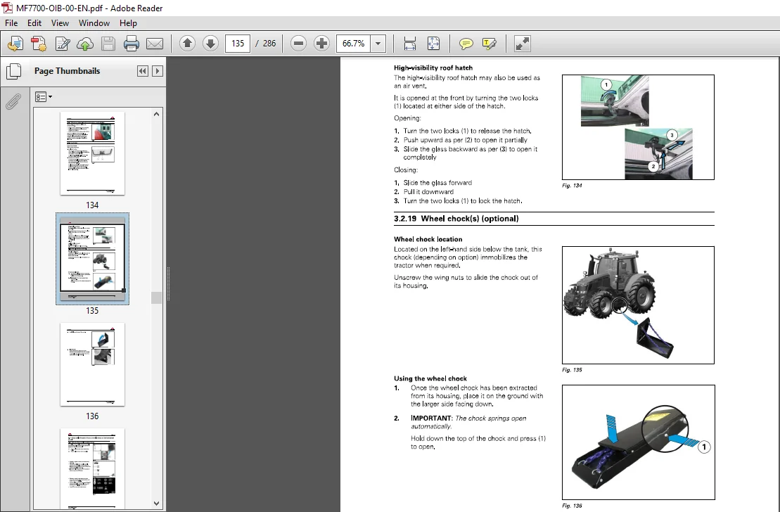
3 2 18 Roof hatch 134
3 2 19 Wheel chock(s) (optional) 135
3 3 Setup and Information Screen control screens on the instrument
panel 137
3 3 1 Using the Setup and Information Screen 137
3 3 2 Setup and Information screens 139
3 4 Body 146
MF 7700 – Operation
ACT001031 B_ed3
3 5
3 6
3 7
3 8
3 9
Table of contents
3 4 1 Opening the bonnet 14 6
3 4 2 Adjusting the external rear-view mirrors 14 6
3 4 2 1 Positioning the arms 14 6
3 4 2 2 Adjusting the arm extensions (depending on model) 14 7
3 4 2 3 Adjusting the rear-view mirrors (depending on model) 14 7
Engine 148
3 5 1 Running-in 14 8
3 5 2 Filling with fuel 14 8
3 5 3 Start switch 15 0
3 5 4 Start-up 15 0
3 5 5 Starting the SCR Technology engine in cold weather 15 1
3 5 6 Information about the various operating modes of the SCR Technology engine 15 3
3 5 7 Stopping the engine 15 8
3 5 8 Engine speed 158
3 5 9 Storing an engine speed 16 0
Transmission 162
3 6 1 Presentation of the different driving modes 16 2
3 6 2 Clutch function 16 2
3 6 3 PowerShuttle 16 3
3 6 3 1 PowerShuttle Protection Function 16 4
3 6 4 Adjusting the start ratios ( 1A , 1B , 1C etc ) 16 5
3 6 4 1 Setting procedure: 16 5
3 6 4 2 Starting ratio 16 5
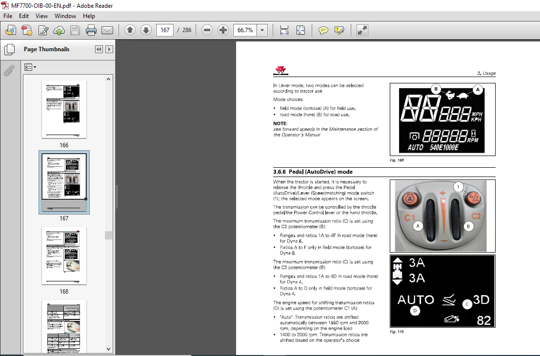
3 6 5 Lever (Speedmatching) mode 16 6
3 6 6 Pedal (AutoDrive) mode 16 7
3 6 7 Road mode (Hare)/Field mode (Tortoise) 16 8
3 6 8 Changing the transmission ratios ( 1A , 1B , 1C , etc ) 16 9
3 6 9 Optional creeper range (snail) 16 9
3 6 10 Tractor towing 17 0
3 6 11 Forward speed calibration 17 0
Brakes 172
3 7 1 B rake pedals 17 2
3 7 2 H ydraulic trailer brake 1 7 2
3 7 3 Pneumatic trailer brake 1 7 3
3 7 4 Parking brake 17 4
Front axle 176
3 8 1 Four-wheel drive front axle 17 6
3 8 2 Suspended front axle 17 7
3 8 3 Permissible load on the front axle 17 9
Differential lock 182
3 9 1 Differential lock 18 2
3 10 Power take-off 184
3 10 1 Front power take-off 18 4
3 10 2 Rear power take-off ( PTO) 18 5
3 10 2 1 Selecting the power take-off speed 18 5
3 10 2 2 Adjusting the progressivity of power-take-off engagement 18 6
3 10 2 3 Engaging PTO in manual mode: 18 7
3 10 2 4 Engaging PTO in automatic mode: 18 7
3 10 3 Economy PTO 18 8
3 10 4 GS PTO (optional) 18 9
3 10 5 Replacing the interchangeable shaft 19 0
3 10 6 Changing the flanged shaft 19 1
3 10 7 PTO external control 19 2
3 10 8 Power take-off electronic controls 19 3
3 10 9 Power take-off protection 19 3
3 11 Linkage 195
3 11 1 General 19 5
MF 7700 – Operation
ACT001031B_ed3
Table of contents
3 11 2 Rear linkage electronic controls 19 6
3 11 3 Rear linkage operation 19 8
3 11 4 Rear linkage external controls 20 3
3 11 5 Front linkage 20 4
3 11 6 Top link 20 7
3 11 7 Bottom links 20 9
3 11 8 Lift rods 210
3 11 9 Stabilizers 211
3 11 9 1 Stabilizers with manual telescopic adjustment 211
3 11 9 2 Automatic stabilizers 213
3 11 10 Ball joint support 214
3 12 Towing equipment 2 15
3 12 1 General 215
3 12 2 Swinging drawbar 217
3 12 2 1 Fitting the swinging drawbar 219
3 12 3 4-wheel trailer clevis hitch 220
3 12 4 Pick-up hitch 222
3 12 4 1 Lowering the hook 222
3 12 4 2 Lifting the hook 223
3 12 4 3 Fitting the swinging drawbar 224
3 13 Auxiliary hydraulics 225
3 13 1 General 225
3 13 2 Description of hydraulic couplers on Open Center system 225
3 13 3 Use of hydraulic couplers on Open Center system 226
3 13 4 Description of hydraulic couplers on Closed Center system (Load Sensing) 229
3 13 5 Use of hydraulic couplers on Closed Center system (Load Sensing) 23 1
3 13 6 Description of the hydraulic controls inside the cab 23 5
3 13 7 Hydraulics control lever 23 6
3 13 8 Open Centre 10 0 I/min 23 7
3 13 8 1 Pump coupling (combined flow) 23 7
3 13 8 2 Pump uncoupling 23 8
3 13 9 Setting flow rates 23 8
3 14 Standard front-end loader function 239
3 14 1 Front-end loader 23 9
3 14 2 Layout of components 23 9
3 14 3 Standard front-end loader connection 24 0
3 14 4 Using the mechanical joystick of the front-end loader 24 1
3 14 4 1 Locking/unlocking the front-end loader control 24 1
3 14 4 2 Joystick in working position 24 1
3 14 4 3 Joystick in rest position 24 2
3 14 4 4 Joystick functions for the front-end loader 24 2
3 14 4 5 Electrical functions for the front-end loader 24 2
3 14 4 6 Floating position 24 3
3 14 4 7 3rd and 4th functions 24 3
3 14 4 8 Arm suspension 24 4
3 14 4 9 Locking and unlocking accessories 24 4
3 15 Lighting 245
3 15 1 Main lighting control module 24 5
3 15 2 Work lights module 24 6
3 15 3 Lighting control for panoramic cabs 24 7
3 16 Suspended cab 249
3 16 1 Suspended cab 24 9
3 17 Front tires and track widths 252
3 17 1 W heel studs 252
3 17 2 I nstallation points of the axle stands 252
3 17 3 Adjusting the front wheel track width 253
3 17 4 Adjusting the 4WD front axle stops 256
MF 7700 – Operation
ACT001031 B_ed3
Table of contents
3 17 4 1 Fitting the oscillation stops 25 6
3 17 4 2 Adjusting the steering angle 25 6
3 17 4 3 Toe-in check 25 7
3 17 4 4 Adjusting the front fenders Shoe side adjustment on the front axle 25 7
3 17 4 5 Adjusting the front fenders Adjusting the lateral position of the fender
on the support (two adjustments are possible) 25 8
3 17 4 6 Adjusting the front fenders Adjusting the height of the support on the
shoe 25 8
3 17 5 Tires 25 8
3 17 6 Tire pressures 25 8
3 18 Rear tires and track widths 259
3 18 1 Wheel studs 25 9
3 18 2 Installation points of the axle stands 25 9
3 18 3 Rear track width with flanged shafts 26 0
3 18 4 Rear track width with short straight shafts 26 2
3 18 5 Rear track width with long straight shafts 26 6
3 18 6 Adjusting the rear wheel track width 26 8
3 18 6 1 Adjustment of wheel position on the straight shaft 26 9
3 18 6 2 Adjustment of wheel position on the straight shaft 26 9
3 19 Dual wheels 27 1
3 19 1 Dual wheels 27 1
3 19 2 Installation points of the axle stands 27 2
3 19 3 Dual rear wheel track width with long straight shafts 27 3
3 19 4 Adjusting the rear wheel track width 27 8
3 19 4 1 Adjustment of wheel position on the straight shaft 27 9
3 19 4 2 Adjustment of wheel position on the straight shaft 27 9
3 20 Ballast 28 1
3 20 1 Liquid ballasting 28 1
3 20 2 Front-end weight 28 1
IMAGES PREVIEW OF THE MANUAL:
PLEASE NOTE:
- This is the same manual used by the DEALERSHIPS to SERVICE your vehicle.
- The manual can be all yours – Once payment is complete, you will be taken to the download page from where you can download the manual. All in 2-5 minutes time!!
- Need any other service / repair / parts manual, please feel free to contact us at heydownloadss @gmail.com . We may surprise you with a nice offer
S.V