Massey Ferguson EU Tractor MF8700 Series 8727 8730 8732 8735 8737 8740 Technician Service Manual – PDF DOWNLOAD
Original price was: $65.95.$29.95Current price is: $29.95.
Massey Ferguson EU Tractor MF8700 Series 8727 8730 8732 8735 8737 8740 Technician Service Manual – PDF DOWNLOAD
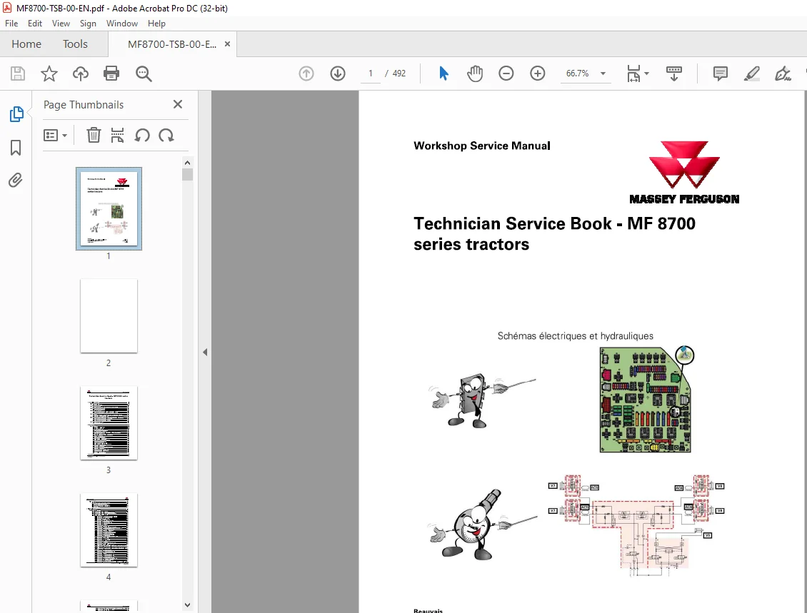
Schemas electriques et hydrauliques
Part. No : ACT0031240
Description
Massey Ferguson EU Tractor MF8700 Series 8727 8730 8732 8735 8737 8740 Technician Service Manual – PDF DOWNLOAD
DESCRIPTION:
Massey Ferguson EU Tractor MF8700 Series 8727 8730 8732 8735 8737 8740 Technician Service Manual – PDF DOWNLOAD
Format: PDF
Language: English
Brand: Massey Ferguson
TABLE OF CONTENTS:
Massey Ferguson EU Tractor MF8700 Series 8727 8730 8732 8735 8737 8740 Technician Service Manual – PDF DOWNLOAD
Schemas electriques et hydrauliques
Part. No : ACT0031240
1 General Information 1-1
1 1 Specifications 1-3
1 1 1 Models MF 8700 1-3
1 2 Forward speeds 1-11
1 2 1 Forward speed for all models with Dyna- VT transmission 1- 1 1
1 3 Dimensions and weights 1-12
1 3 1 Dimensions and weights 1- 1 2
1 4 Attachment points 1-14
1 4 1 Attachment points: Dyna- VT models with 5 t front linkage 1- 14
1 4 2 Attachment points: Dyna- VT models without front linkage 1- 1 5
1 5 capacities 1-17
1 5 1 Capacities for models with a Tier 4F /Stage I V SCR Technology engine 1- 1 7
1 5 2 Accumulator pressure and volume 1- 1 7
1 6 Tightening torques, retaining compounds and sealing products 1-18
1 6 1 Retaining compounds and sealing products 1- 18
1 6 2 Tightening torques for screws and nuts 1- 19
1 6 3 Tightening torques for hydraulic unions 1- 23
1 7 Units of measurement 1-27
1 7 1 Conversion table 1- 27
2 Error codes 2-1
2 1 Error codes 2-3
2 1 1 General table of faults 2-3
2 1 2 Indicator light panel 2-6
2 1 3 Indication of faults 2- 14
2 1 4 Description of error code format 2- 1 7
2 1 5 Instrument panel error codes 2- 19
2 1 6 Error codes Tier 4F /Stage IV SCR Technology engineA GCO Power 2- 19
2 1 7 Error codes: transmission 2-37
2 1 8 4-wheel drive and differential lock error codes 2-4 2
2 1 9 Armrest error codes 2-4 2
2 1 1 0 Auto-Guide error codes 2-43
2 1 1 1 Suspended cab error codes 2-4 5
2 1 1 2 Main controller error codes 2-46
2 1 1 3 Pillar membrane keypad error codes 2-46
2 1 14 Air conditioning error codes 2-47
2 1 1 5 Dri ving error codes 2-48
2 1 1 6 Steering system error codes 2-49
2 1 17 Electrohydraulic spool valve error codes 2-5 2
2 1 18 Brake system error codes 2-53
2 1 19 Hydraulic error codes 2-55
2 1 20 Datatronic 5 and error codes AgCommand™ 2-56
2 1 2 1 Front axle error codes 2-57
2 1 2 2 Error codes: rear power take-off 2-57
2 1 23 Front power take-off error codes 2-59
2 1 24 E rror codes: rear linkage 2-59
2 1 25 Front linkage error codes 2-6 0
3 Fuse box 3-1
Technician Service Book- MF 8700 series tractors
ACT0031240
Table of contents
3 1 Fuse box 3-3
3 1 1 Identification table of fuse box elements 3-3
3 1 2 Description of the main fuse box 3-3
3 1 3 Description of the secondary fuse box 3- 13
3 1 4 Description of additional fuses and relays 3- 16
3 1 5 Battery isolator 3- 19
4 Electrical diagrams 4-1
4 1 Electrical diagrams 4-3
4 1 1 Identification of electrical diagrams 4-3
4 1 2 Identification of electrical connectors from X1 to X5 00 4- 5
4 1 3 Identification of electrical connectors from X5 01 to X1 000 4- 17
4 1 4 Identification table for cable colors 4-26
4 1 5 Electrical diagrams 4-29
4 1 5 1 EFD00000_9 – Battery 12 V power supply points 4-29
4 1 5 2 EFD00000_ 1 0- Battery earth points 4-30
4 1 5 3 EFD001 00_2 0 – 4- wheel drive 4-32
4 1 5 4 EFD001 01_2 0 – Differential lock 4-33
4 1 5 5 EFD001 05_ 5 – Auxiliary hydraulic oil gage 4-34
4 1 5 6 EFD001 06_36 – Rear power take- off 4-35
4 1 5 7 EFD001 07_ 1 5 – Front power take- off 4-36
4 1 5 8 EFD001 1 1_39 – Drive train 4-37
4 1 5 9 EFD001 13_9 – Lighter 4-38
4 1 5 1 0 EFD001 14_31 – EAME radio 4-39
4 1 5 1 1 EFD001 16_ 13 – Hydraulic active suspended cab 4-4 0
4 1 5 12 EFD001 17_ 35 – Automatic air conditioning unit power supply 4 -4 1
4 1 5 13 EFD001 17_ 36 – Automatic air conditioning 4-42
4 1 5 14 EFD001 17_ 37- Manual air conditioning 4-43
4 1 5 1 5 EFD001 17_ 38 – Additional heater 4-44
4 1 5 16 EFD001 18_8 – Setup and information screen 4-4 5
4 1 5 17 EFD001 19_ 12 – Rear windscreen wiper 4-46
4 1 5 18 EFD0012 0_ 1 1 – Front windscreen wiper 4-47
4 1 5 19 EFD0012 1_ 13- Parking brake 4-48
4 1 5 2 0 EFD0012 1_ 14 – Parking brake (Mother Regulation) 4-49
4 1 5 2 1 EFD00122_ 1 0- Fuel gage 4- 5 0
4 1 5 22 EFD00123_32 – Datatronic 5 4- 5 1
4 1 5 23 EFD00123_33 – Auto- Guide™ 4- 52
4 1 5 24 EFD00123_34 – lsobus 4- 53
4 1 5 2 5 EFD00124_ 13 – Parklock 4- 54
4 1 5 26 EFD00124_ 14 – Parklock (Mother Regulation) 4- 5 5
4 1 5 27 EFD0012 5_ 1 1 – Cab light 4- 56
4 1 5 28 EFD0012 5_ 12 – Cab light and step lighting 4- 57
4 1 5 29 EFD00126_ 1 5 – Extreme cold weather heating with automatic air
conditioning 4- 58
4 1 5 30 EFD00126_ 16 – Extreme cold weather heating with manual air
conditioning 4- 59
4 1 5 31 EFD00128_22 – Cab current socket 4-6 0
4 1 5 32 EFD00129_ 14 – Diagnostics connector – 1/2 4-6 1
4 1 5 33 EFD00129_ 14 – Diagnostics connector – 2/2 4-62
4 1 5 34 EFD00130_8 – Radar 4-64
4 1 5 35 EFD00131_43- CAN network tractor- 1/5 4-6 5
4 1 5 36 EFD00131_43- CAN network engine – 2/5 4-66
4 1 5 37 EFD00131 _ 43 – CAN network hydraulic – 3/5 4-67
4 1 5 38 EFD00131_43- CAN network isobus – 4/5 4-68
4 1 5 39 EFD00131_43- CAN networkAGCO Power- 5/5 4-69
4 1 5 4 0 EFD00132_9 – Electric rear- view mirrors 4-70
4 1 5 4 1 EFD00133_8 – Pneumatic seat 4-71
4 1 5 42 EFD00136_67- EAME direction indicators and flashing warning lights 4 -72
Technician Service Book- MF 8700 series tractors
ACT0031240
Table of contents
4 1 5 43 EF D00 1 36_68 -NA direction indicators and flashing warning lights 4-7 3
4 1 5 44 EFD00 1 37 _ 27 -N umber plate lighting 4-7 4
4 1 5 45 EFD00138_4 4 -Side lights 4-7 5
4 1 5 46 EFD00138_4 6 -Daytime driving lamps 4-7 6
4 1 5 47 EF D00 1 39 _ 1 3 – Reversing light 4-77
4 1 5 48 EFD00 140_4 4 -High beam lamps and low beam lamps on grille 4 -7 8
4 1 5 49 EFD00140_4 5 -High beam lamps and low beam lamps on grille + hand
rail 4-7 9
4 1 5 50 EF D00 14 1_9 8 – EAME work lights 4-8 0
4 1 5 5 1 EF D00 14 1_9 9 – EAME LED work lights 4-8 1
4 1 5 5 2 EF D00 14 1_ 1 00 -NA work lights 4-8 2
4 1 5 53 EF D00 14 1_ 1 0 1 -NA LED work lights 4-8 3
4 1 5 54 EF D00 14 2_ 1 5 -Brake lights 4-84
4 1 5 55 EFD00 143_ 29 -Rotary beacon 4-8 5
4 1 5 56 EF D00 144_ 1 0 -Control module 4-8 6
4 1 5 57 EF D00 145_ 18 – EAME trailer connector 4-87
4 1 5 58 EF D00 14 5_ 19 – NA trailer connector 4-88
4 1 5 59 EF D00 148_ 1 5 -Audible alarm 4-89
4 1 5 6 0 EF D00 149_2 1 – Battery charge + jump start 4-9 0
4 1 5 6 1 EF D00 1 50_ 1 1 -Air filter vacuum sensor 4-9 1
4 1 5 6 2 EF D00 1 5 1_39 – EEM unit power supply A GCO Power 4-9 2
4 1 5 63 EFD001 5 1_4 0 -Engine electronic injection AGCO Power 4-9 3
4 1 5 64 EF D00 1 5 2 _ 20 – DANA suspended front axle 4-9 4
4 1 5 6 5 EFD00 1 53_ 18 – Preheating power supply A GCO Power 4-9 5
4 1 5 6 6 EFD00 1 54_5 – Fuel preheater 4-9 6
4 1 5 67 EF D00 1 57 _ 1 0 – Vistronic 4-97
4 1 5 68 EF D00 1 59 _ 20 – Hydraulic spool valves 4-9 8
4 1 5 69 EF D00 1 6 0_34 -Rear linkage and Dual Control 4-9 9
4 1 5 7 0 EF D00 1 6 1_ 14 – Front linkage 4- 1 00
4 1 5 7 1 EF D00 1 6 2_ 1 3 – Dual Control linkage and trailed implements (TIC) 4- 1 0 1
4 1 5 7 2 EFD00 163_1 1 – Console lighting 4- 102
4 1 5 7 3 EF D00 1 69 _2 2 -Controller power supply – 1/5 4- 1 03
4 1 5 7 4 EF D00 1 69 _2 2 -Controller power supply – 2 /5 4- 1 04
4 1 5 7 5 EF D00 1 69 _2 2 -Controller power supply – 3/5 4- 1 05
4 1 5 7 6 EF D00 1 69_2 2 -Controller power supply – 4/5 4- 1 06
4 1 5 77 EF D00 1 69 _ 2 2 -Controller power supply – 5/5 4- 1 07
4 1 5 7 8 EFD0017 2_7 – Front accessory connection socket 4- 108
4 1 5 7 9 EFD00 17 3_6 -Water-in-fuel sensor ( 84 AWF engine) 4- 1 09
4 1 5 8 0 EF D00 17 4_ 1 6 -Air brake 4- 1 1 0
4 1 5 8 1 EF D00 17 4_ 17 -Air brake (Mother Regulation) 4- 1 1 1
4 1 5 8 2 EF D00 17 5 – Engine A GCO Power 49 /84 AWF _ 1/3 4- 1 1 2
4 1 5 8 3 EF D00 17 5 – Engine A GCO Power 49 /6 6/7 4/84 AWF _ 2/3 4- 1 1 3
4 1 5 84 EF D00 17 5 – Engine A GCO Power 49 /6 6/7 4/84 AWF _3/3 4- 1 14
4 1 5 8 5 EF D00 17 5_ 1 0 -SCR Technology EAME 4- 1 1 5
4 1 5 8 6 EF D00 17 5_ 1 1 -SCR Technology NA 4- 1 1 6
4 1 5 87 EF D00 17 6_ 18 – EAME ALO loader 4- 1 17
4 1 5 8 8 EF D00 17 6_ 19 – NA ALO loader 4- 1 18
4 1 5 89 EF D00177 _6 -Auto-hitch ?1– 1 19
4 1 5 9 0 EF D00 17 8_7 – Steering SpeedSteer 4- 1 20
4 1 5 9 1 EF D00 18 3_3 – Implement attachment without lsobus 4- 1 2 1
4 1 5 9 2 EF D00 184_7 -AgCommand™ 4- 1 2 2
5 Harnesses 5-1
5 1 Harnesses 5-5
5 1 1 Identification of harnesses 5-5
5 1 2 Harnesses 5-9
5 1 2 1 FAl 2 00 – Engine harness 84 AWF – ACW040249 5-9
5 1 2 2 FAl 2 00 – Engine harness 84 AWF -ACW 19 504 1 5- 1 0
Technician Service Book- MF 8700 series tractors
ACT0031240
Table of contents
5 1 2 3 FAl20 1 – Front headlights harness – 4384 1 33_ 1/2 5- 1 1
5 1 2 4 FAl20 1 – Front headlights harness – 4384 1 33_ 2/2 5- 1 2
5 1 2 5 FAl20 1 – Front headlights harness -ACW06 2344 5- 1 3
5 1 2 6 FAl20 2 -Suspended front axle harness -ACW050 230 5- 14
5 1 2 7 FAl 20 2 – Fixed front axle harness -ACW057 1 6 2 5- 1 5
5 1 2 8 FAl203 – Dri ve train harness -ACW076735 5- 1 6
5 1 2 9 FAl 205 – Electrohydraulic valves harness – 4 29 209 0 5- 1 7
5 1 2 1 0 FAl 205 – Electrohydraulic val ves harness – 4 29 209 1 5- 18
5 1 2 1 1 FAl 205 – Electrohydraulic valves harness – 4 29 209 2 5- 19
5 1 2 1 2 FAl 205 – Electrohydraulic val ves harness – 4 29 209 3 5- 20
5 1 2 1 3 FAl 208 – Linkage with Dual Control and TIC harness – 438 779 7 1 / 2 5- 2 1
5 1 2 14 FAl 208 – Linkage with Dual Control and TIC harness – 438 779 7 2/2 5- 2 2
5 1 2 1 5 FAl 2 1 0 -Cab dri ve train harness -ACW0 26 547 5- 23
5 1 2 1 6 FAl 2 14 -Armrest harness -ACW0309 03 5- 24
5 1 2 17 FAl 2 19 -Cab interior current socket harness – 4 29 0574_ 1/2 5- 25
5 1 2 18 FAl 2 19 -Cab interior current socket harness – 4 29 0574_ 2/2 5- 26
5 1 2 19 FAl 2 19 -Cab interior current socket harness – 4 29 0575_ 1/2 5- 27
5 1 2 20 FAl 2 19 -Cab interior current socket harness – 4 29 0575_2/2 5- 28
5 1 2 2 1 FAl 2 23 -Roof harness EAME – 4389 1 79 _ 1/2 5- 29
5 1 2 2 2 FAl 2 23 -Roof harness EAME – 4389 1 79 _2/2 5-30
5 1 2 23 FAl 2 23 -Roof harness NA – 4389 18 3_ 1/2 5-3 1
5 1 2 24 FAl 2 23 -Roof harness NA – 4389 18 3_ 2/2 5-3 2
5 1 2 25 FAl 2 25 – Electric rear-view mirror harness – 4389 18 5_ 1/2 5-33
5 1 2 26 FAl 2 25 – Electric rear-view mirror harness – 4389 18 5_ 2/2 5-34
5 1 2 27 FAl 2 27 – Roof harness with automatic air conditioning EAME –
4389 18 0_ 1 /2 5-35
5 1 2 28 FAl 2 27 – Roof harness with automatic air conditioning EAME –
4389 18 0_ 2/2 5-36
5 1 2 29 FAl 2 27 – Roof harness with automatic air conditioning NA – 4389 184_ 1/2
5-37
5 1 2 3 0 FAl 2 27 – Roof harness with automatic air conditioning NA – 4389 184_2/2
5-38
5 1 2 3 1 FAl 2 28 -N umber plate lighting harness – 4 29 9 633_ 1/2 5-39
5 1 2 3 2 FAl 2 28 -N umber plate lighting harness – 4 29 9 633_2/2 5-40
5 1 2 33 FAl 23 2 -Radio harness -ACW 109 1 25 5-4 1
5 1 2 34 FAl 23 2 -Radio harness -ACW 109 1 27 5-4 2
5 1 2 3 5 FAl 243 -Circuit breaker harness -ACW05 1 6 6 2 5-43
5 1 2 36 FAl 253 – Hand rail harness – 439 0 26 2_ 1/ 2 5-44
5 1 2 37 FAl 253 – Hand rail harness – 439 0 26 2_ 2/ 2 5-4 5
5 1 2 38 FAl 253 – Hand rail harness -ACW039 63 0 5-46
5 1 2 39 FAl 26 1 – lsobus harness – 4349 6 59 _ 1/2 5-47
5 1 2 40 FAl 26 1 – lsobus harness – 4349 6 59 _ 2/2 5-48
5 1 2 4 1 FAl 26 2 -Auto-Guide™ engine harness -ACW03 58 2 2 5-49
5 1 2 4 2 FAl 263 -Auto-Guide™ cab adapter harness -ACW03 239 6 5-50
5 1 2 43 FAl 264 -Auto-Guide™ roof adapter harness -ACW03 288 0 5-5 1
5 1 2 44 FAl 26 5 -Air brake harness -ACW0 27 149 5-5 2
5 1 2 4 5 FAl 26 5 -Air brake harness -ACW 143406_ 1/2 5-53
5 1 2 46 FAl 26 5 -Air brake harness -ACW 143406_2/2 5-54
5 1 2 47 FAl 268 – Front function harness – 4 29 3 1 00_ 1/2 5-55
5 1 2 48 FAl 268 – Front function harness – 4 29 3 1 00_ 2/2 5-56
5 1 2 49 FAl 273 – Front linkage harness without accessory connection socket –
ACW0 279 8 7 5-57
5 1 2 50 FAl 273 – Front linkage harness with accessory connection socket –
ACW0448 67 5-58
5 1 2 5 1 FAl 274 -Rear right-hand lighting harness – 4384 19 0_ 1/2 5-59
5 1 2 5 2 FAl 274 -Rear right-hand lighting harness – 4384 19 0_ 2/2 5-6 0
5 1 2 53 FAl 275 -Trailer connector harness EAME with IS OBUS – 4 289 36 2_ 1/2 5-6 1
5 1 2 54 FAl 275 -Trailer connector harness EAME with ISO BUS – 4 289 36 2_2/2 5-6 2
Technician Service Book- MF 8700 series tractors
ACT0031240
Table of contents
5 1 2 55 FAl 275 -Trailer connector harness NA with IS OBUS – 4 289 363_ 1/2 5-63
5 1 2 56 FAl 275 -Trailer connector harness NA with IS OBUS – 4 289 363_ 2/2 5-64
5 1 2 57 FAl 275 -Trailer connector harness NA – 4 29 00 1 1_ 1/2 5-6 5
5 1 2 58 FAl 275 -Trailer connector harness NA – 4 29 00 1 1 2/2 5-6 6
5 1 2 59 FAl 275 -Trailer connector harness E AME – 4 29 00 1 2_ 1/2 5-67
5 1 2 60 FAl 275 -Trailer connector harness E AME – 4 29 00 1 2_2/2 5-68
5 1 2 6 1 FAl 276 -Rear left-hand lighting harness – 4348 767 _ 1/2 5-69
5 1 2 6 2 FAl 276 -Rear left-hand lighting harness – 4348 767 _2/2 5-70
5 1 2 63 FAl 28 0 -N egative battery harness – 4355659 5-7 1
5 1 2 64 FAl 28 3 -TopDock harness -ACW03 2708 5-7 2
5 1 2 6 5 FAl 284 – Harness for 4WD, differential and power take-off solenoid
valves -ACW0 26536 5-73
5 1 2 6 6 FAl29 0 -N on-lsobus implement connector harness- 1/2 5-74
5 1 2 67 FAl29 0 -N on-lsobus implement connector harness- 2/2 5-75
5 1 2 68 FAl 29 2 -NA direction indicator harness – 437678 0_ 1/2 5-76
5 1 2 69 FAl 29 2 -NA direction indicator harness – 437678 0_ 2/2 5-77
5 1 2 70 FAl 29 2 -NA direction indicator harness- 1/ 2 5-78
5 1 2 7 1 FAl 29 2 -NA direction indicator harness- 2/ 2 5-79
5 1 2 7 2 FAl 29 3 – EAME direction indicator harness – 43833 17_ 1 /2 5-80
5 1 2 73 FAl 29 3 – EAME direction indicator harness – 43833 17_ 2/2 5-8 1
5 1 2 74 FAl 29 4 -Additional heater harness – 4 29 9 3 27 1/2 5-8 2
5 1 2 7 5 FAl 294 -Additional heater harness – 4 29 9 3 27_ 2/2 5-83
5 1 2 76 FAl 29 5 -NA ALO loader harness – 4348 364_ 1/2 5-84
5 1 2 77 FAl 29 5 -NA ALO loader harness – 4348 364_ 2/2 5-8 5
5 1 2 78 FAl 29 6 – E lectrohydraulic valves shunt harness – 4 29 5666 5-8 6
5 1 2 79 FAl300 -Air conditioning shunt harness – 4 29 639 2 5-8 7
5 1 2 8 0 FAl304 -Additional fan harness – 4 29 7 139_ 1/2 5-88
5 1 2 8 1 FAl304 -Additional fan harness – 4 29 7 139_ 2/2 5-89
5 1 2 8 2 FAl305 – E ngine exhaust harness – 4348876 5-9 0
5 1 2 8 3 FAl305 – E ngine exhaust harness – 4353 133 5-9 1
5 1 2 84 FAl307 – Harness Datatronic 5 -ACW 1 5040 2 5-9 2
5 1 2 8 5 FAl307 – Harness Datatronic 5 -ACW 1 50403_ 1/2 5-9 3
5 1 2 8 6 FAl307 – Harness Datatronic 5 -ACW 1 50403_2/2 5-9 4
5 1 2 8 7 FAl307 – Harness Datatronic 5 -ACW 1 50404 5-9 5
5 1 2 8 8 FAl3 1 0 – Battery/battery isolator negative cable harness – 4355556 5-9 6
5 1 2 89 FAl3 1 0 – Battery/battery isolator negative cable harness – 4355557 5-9 7
5 1 2 9 0 FAl3 1 0 – Battery/battery isolator negative cable harness – 4355658 5-9 8
5 1 2 9 1 FAl3 1 1 – Battery/starter positi ve cable harness – 4355558 5-9 9
5 1 2 9 2 FAl3 1 1 – Battery/starter positi ve cable harness – 4355559 5- 1 00
5 1 2 9 3 FAl3 1 1 – Battery/starter positi ve cable harness -ACW 1 1 19 53 5- 1 0 1
5 1 2 9 4 FAl3 14 -Alternator harness -ACW05 1 6 8 2 5- 1 0 2
5 1 2 9 5 FAl3 26 -Rear linkage harness – 435 29 59 _ 1 /2 5- 1 03
5 1 2 9 6 FAl3 26 -Rear linkage harness – 435 29 59 _ 2/2 5- 1 04
5 1 2 9 7 FAl355 – Harness for the left-hand alternator and grid heater –
ACW05 1 6 6 3 5- 1 05
5 1 2 9 8 FAl363 – Hand rail harness – 439 0 208_ 1 /2 5- 1 06
5 1 2 9 9 FAl363 – Hand rail harness – 439 0 208_2/2 5- 1 07
5 1 2 1 00 FAl368 – LE D light adapter harness -ACW0747 1 3_ 1/2 5- 1 08
5 1 2 1 0 1 FAl368 – LE D light adapter harness -ACW0747 1 3_ 2/ 2 5- 1 09
5 1 2 1 0 2 FAl37 1 -Adapter harness Auto-Guide™ -ACW04 1 06 5 5- 1 1 0
5 1 2 103 FAl37 2 -Adapter harness Auto-Guide™N ovatel -ACW0330 18 5- 1 1 1
5 1 2 1 04 FAl373 -Adapter harness Auto-Guide™Trimble® -ACW04 1 064 5- 1 1 2
5 1 2 1 05 FAl374 -Temperature sensor adapter harness -ACW 1 6 8 05 2 5- 1 1 3
5 1 2 106 FAl379 -ABS trailer connector harness -ACW 1 1 69 43_ 1 /2 5- 1 14
5 1 2 1 07 FAl379 -ABS trailer connector harness -ACW 1 1 69 43_ 2/2 5- 1 1 5
6 Hydraulics diagrams 6-1
6 1 Hydraulics diagrams 6-3
Technician Service Book- MF 8700 series tractors
ACT0031240
Table of contents
6 1 1 Hydraulics diagrams 6-5
6 1 1 1 HF D0 1 054 -Auxiliary hydraulics diagram: all options (Mother Regulation) 6-5
6 1 1 2 HF D0 1 054 -Auxiliary hydraulics diagram: all options 6-6
6 1 1 3 HF D0 1 055 -Standard auxiliary hydraulics diagram (Mother Regulation) 6-7
6 1 1 4 HF D0 1 055 -Standard auxiliary hydraulics diagram 6-8
6 1 1 5 HF D0 20 1 3 – Hydraulics diagram: steering system Auto-Guide™ 6-9
6 1 1 6 HF D0 20 14 – Hydraulics diagram: standard steering system 6- 1 0
6 1 1 7 HF D0307 1 – Hydraulics diagram: brake system with trailer brake (Mother
Regulation) 6- 1 1
6 1 1 8 HF D0307 1 – Hydraulics diagram: brake system with trailer brake 6- 1 2
6 1 1 9 HF D0307 2 – Hydraulics diagram: brake system without trailer brake
(Mother Regulation) 6- 1 3
6 1 1 1 0 HF D0307 2 – Hydraulics diagram: brake system without trailer brake 6- 14
6 1 1 1 1 HFD04007 – Hydraulics diagram: rear linkage 6- 1 5
6 1 1 1 2 HF D050 1 0 – Hydraulics diagram: front linkage 6- 1 6
6 1 1 1 3 HFD06 0 1 5 – Hydraulics diagram: auxiliary hydraulic spool valves 6- 1 7
6 1 1 14 HF D07007 – Hydraulics diagram: auto-hitch 6- 18
6 1 1 1 5 HF D08 007 – Hydraulics diagram: suspended front axle 6- 19
6 1 1 1 6 HF D09 009 – Hydraulics diagram: suspended cab 6- 20
6 1 1 17 HF D 1 00 1 6 – Hydraulics diagram: EAME loader 6- 2 1
6 1 1 18 HFD 1 00 1 7 – Hydraulics diagram: NA loader 6- 2 2
6 1 1 19 Transmission hydraulics diagram 6- 23
7 Pneumatic diagrams 7-1
7 1 Pneumatic diagrams 7-3
7 1 1 Pneumatic diagrams 7-5
7 1 1 1 PF D0 1 0 1 1 -Trailer brake pneumatic diagram 7-5
7 1 1 2 PF D0 1 0 18 -Trailer brake pneumatic diagram (Mother Regulation) 7-6
8 Adjustments, bleeding and calibrations 8-1
8 1 Bleeding 8-3
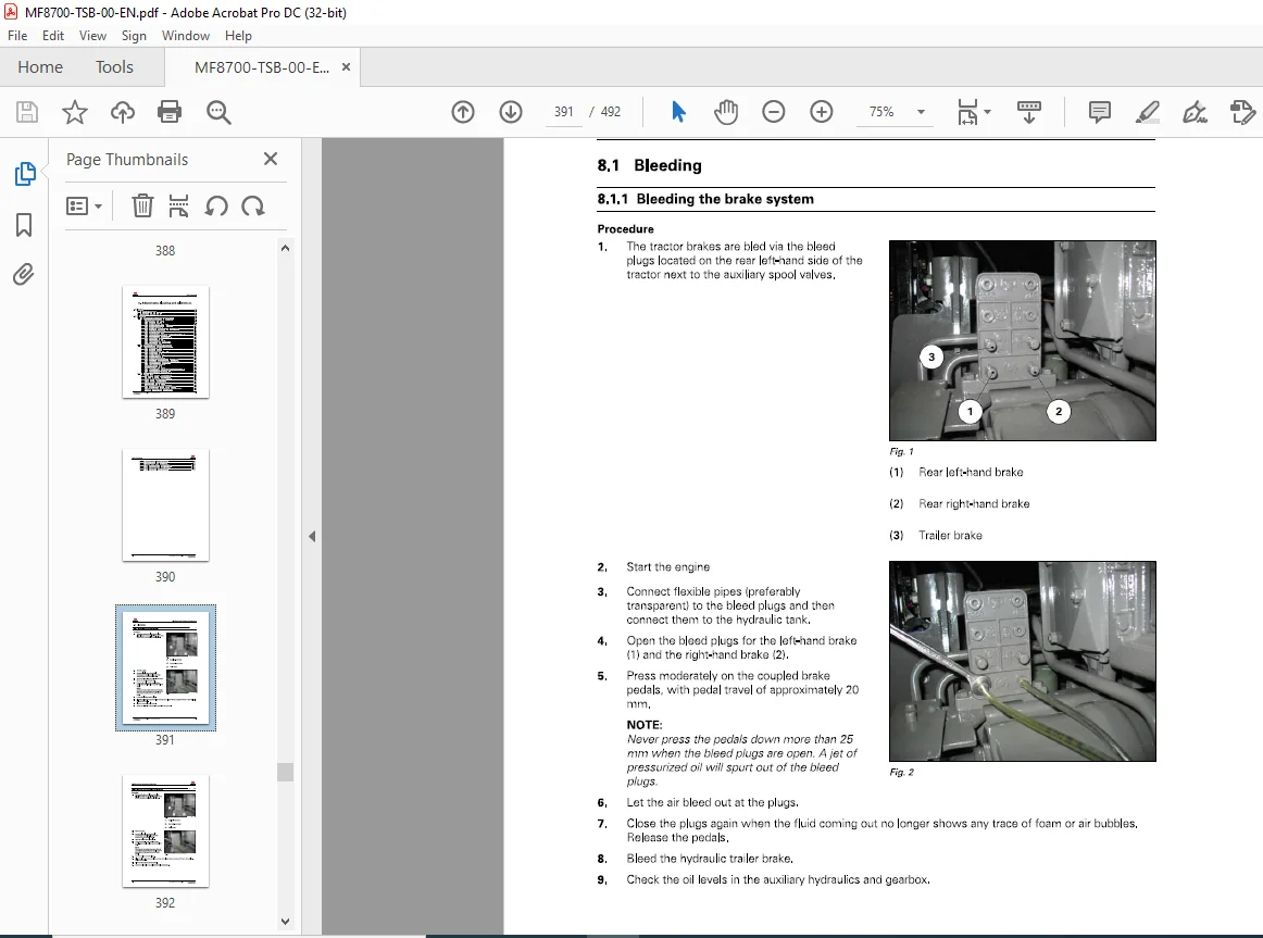
8 1 1 Bleeding the brake system 8-3
8 1 2 Bleeding the hydraulic trailer brake 8-4
8 1 3 Pneumatic trailer brake bleed plug 8-5
8 2 Calibrations 8-6
8 2 1 Calibrations to be carried out using the instrument panel 8-6
8 2 1 1 Access to instrument panel calibration screen 8-6
8 2 1 2 Rear power take-off calibration 8-7
8 2 1 3 Calibrating the clutch pedal 8-9
8 2 1 4 Calibration of the throttle pedal sensor 8- 1 0
8 2 1 5 Calibration of the forward travel lever sensor 8- 1 2
8 2 1 6 Calibration of the Finger Tl Ps 8- 1 3
8 2 1 7 Calibration of the left/right steering angle sensor (WAS) 8- 17
8 2 1 8 Calibrate the suspended front axle 8- 19
8 2 1 9 Calibrating the suspended cab 8- 20
8 2 1 1 0 Calibration of the high/low speed ranges (Hare/Tortoise) Dyna- VT 8- 2 2
8 2 1 1 1 Calibration of the transmission Dyna- VT 8- 23
8 2 1 1 2 Calibration of the coupler function Dyna- VT 8- 25
8 2 1 1 3 Calibrating the rear linkage 8- 26
8 2 1 14 Calibration of the front linkage 8- 28
8 2 1 1 5 Calibration of the hydraulic steering unit 8-30
8 2 1 1 6 Forward speed calibration 8-3 1
8 2 2 Calibrations to be carried out using the diagnostic tool 8-33
8 2 2 1 Access to the calibration menu through EDT 8-33
8 2 2 2 Calibrating the throttle pedal 8-34
8 2 2 3 Calibrating the clutch pedal 8-38
8 2 2 4 Calibration of the forward-travel lever 8-4 2
Technician Service Book- MF 8700 series tractors
ACT0031240
Table of contents
8 2 2 5 Calibrating the rear linkage 8-47
8 2 2 6 Calibration of the front linkage 8-5 1
8 2 2 7 Calibration of the FingerTIPs 8-55
8 2 2 8 Calibrate the suspended front axle 8-60
8 2 2 9 Calibration of the centring steering angle sensor (WAS) 8-64
8 2 2 1 0 Calibration of the left/right steering angle sensor (WAS) 8-67
8 2 2 1 1 Calibration of the hydraulic steering unit 8-7 1
8 2 2 1 2 Calibrating the suspended cab 8-75
8 2 2 1 3 Forward speed calibration 8-78
8 2 2 14 Rear power take-off calibration 8-8 2
8 2 2 1 5 Calibration of the high/low speed ranges (Hare/Tortoise) Dyna- VT 8-8 5
8 2 2 1 6 Calibration of the transmission Dyna- VT 8-88
8 2 2 1 7 Calibration of the coupler function Dyna- VT 8-9 2
8 2 3 Calibration error codes 8-9 6
8 2 3 1 Throttle pedal sensor calibration error code 8-9 6
8 2 3 2 Clutch pedal sensor calibration error code 8-9 6
8 2 3 3 Forward lever sensor calibration error code 8-9 7
8 2 3 4 Rear linkage calibration error code 8-9 7
8 2 3 5 Front linkage calibration error code 8-9 7
8 2 3 6 FingerType calibration error code 8-9 7
8 2 3 7 Suspended front axle calibration error code 8-9 8
8 2 3 8 Angle sensor (WAS) centring calibration error code 8-9 8
8 2 3 9 Left/right steering angle sensor (WAS) calibration error code 8-9 8
8 2 3 1 0 Hydraulic steering unit calibration error code 8-9 8
8 2 3 1 1 Suspended cab calibration error codes 8-9 9
8 2 3 1 2 Forward speed calibration error code 8-9 9
8 2 3 1 3 Rear power take-off calibration error code 8- 1 00
8 2 3 14 High/low speed range calibration error code 8- 1 00
8 2 3 1 5 Dyna- VT transmission calibration error code 8- 1 00
8 2 3 1 6 Coupler function calibration error code 8- 1 0 2
MASSEY FERGUSON EU TRACTOR MF8700 SERIES 8727 8730 8732 8735 8737 8740 TECHNICIAN SERVICE MANUAL – PDF DOWNLOAD:
IMAGES PREVIEW OF THE MANUAL:
PLEASE NOTE:
- This is the same manual used by the DEALERSHIPS to SERVICE your vehicle.
- The manual can be all yours – Once payment is complete, you will be taken to the download page from where you can download the manual. All in 2-5 minutes time!!
- Need any other service / repair / parts manual, please feel free to contact us at heydownloadss @gmail.com . We may surprise you with a nice offer
S.V