Massey Ferguson EU Tractor MFGC Series GC1705 GC1710 GC1715 GC1720 Sub-Compact Service Manual – PDF DOWNLOAD
Original price was: $53.95.$31.95Current price is: $31.95.
Massey Ferguson EU Tractor MFGC Series GC1705 GC1710 GC1715 GC1720 Sub-Compact Service Manual – PDF DOWNLOAD
Description
Massey Ferguson EU Tractor MFGC Series GC1705 GC1710 GC1715 GC1720 Sub-Compact Service Manual – PDF DOWNLOAD
DESCRIPTION:
Massey Ferguson EU Tractor MFGC Series GC1705 GC1710 GC1715 GC1720 Sub-Compact Service Manual – PDF DOWNLOAD
This manual:
This manual covers general safety practices for this machine. The operator manual must always be kept with the machete. Right-hand and left-hand, as used in this manual, are determined by facing the direction the machine will travel when in use. The photos, illustrations. and data used in this manual were current at the time of printing, but due to possible in-line production changes. your machine can vary slightly in detail. The manufacturer reserves the right to redesign and change the machine as necessary without notification.
IMAGES PREVIEW OF THE MANUAL:
TABLE OF CONTENTS:
Massey Ferguson EU Tractor MFGC Series GC1705 GC1710 GC1715 GC1720 Sub-Compact Service Manual – PDF DOWNLOAD
1 Introduction 1-1
1 1 Introduction 1-3
1 1 1 This manual 1-3
1 1 2 Units of measurement 1-3
1 1 3 Serial number plate 1-3
1 1 4 Chassis number 1-4
1 1 5 Engine identification 1-4
1 2 Specifications 1-5
1 2 1 Engine specifications 1-5
1 2 2 Transmission specifications 1-5
1 2 3 Power takeoff specifications 1-6
1 2 4 Hydraulic specifications 1-6
1 2 5 Electrical specifications 1-6
1 2 6 Capacities 1-7
1 2 7 Tread width 1-7
1 2 8 Maximum axle capacity 1-7
1 2 9 Dimensions 1-8
1 3 Lubrication and periodic maintenance 1-10
1 3 1 Lubrication specifications 1-10
1 3 2 Fuel specifications 1-10
1 3 3 Lubrication and maintenance chart 1-10
1 3 4 Lubrication, fill, and drain locations 1-1 2
1 3 5 Bolt torque chart 1-1 3
1 3 6 Conversion table 1-1 4
2 Safety 2-1
2 1 Introduction 2-3
2 1 1 Safety alert symbol 2-3
2 1 2 Safety messages 2-3
2 1 3 Informational messages 2-3
2 1 4 Safety signs 2-4
2 1 5 A word to the operator 2-4
2 1 6 This manual 2-5
2 2 Operation 2-6
2 2 1 Prepare for operation 2-6
2 2 2 Roll over protective structure 2-6
2 2 3 General information 2-6
2 2 4 Personal protective equipment 2-10
2 2 5 Seat instruction 2-10
2 2 6 Shield and guards 2-1 1
2 2 7 Power takeoff safety 2-1 1
2 2 8 Exhaust warning 2-1 2
2 2 9 Flying debris 2-1 2
2 2 10 Agricultural chemicals 2-1 2
2 3 Travel on public roads 2-1 4
2 4 Maintenance 2-1 6
2 4 1 General maintenance information 2-1 6
2 4 2 Fire prevention and first aid 2-1 7
2 4 3 High pressure leaks 2-1 8
2 4 4 Engine safety 2-1 9
GC1705/ GC1710/ GC1715/ GC1720
4283491M1
Table of contents
2 4 5
2 4 6
2 4 7
2 4 8
Fuel safety 2-2 0
Battery safety 2-2 1
Tire safety 2-2 1
Replacement parts 2-2 2
3 Engine 3-1
3 1 Engine 3-3
3 1 1 Opening the hood 3-3
3 1 2 Checking the engine oil level 3-4
3 1 3 Changing the engine oil 3-4
3 1 4 Replacing the engine oil filter 3-5
3 1 5 Engine belt 3-5
3 1 6 Adjusting the engine belt 3-6
3 1 7 Removing the engine 3-6
3 1 8 Installing the engine 3-10
3 2 Engine air filter 3-1 1
3 2 1 Cleaning the engine air filter 3-1 1
3 3 Cooling System 3-1 3
3 3 1 Antifreeze 3-1 3
3 3 2 Thermostat 3-1 3
3 4 Fuel system 3-1 4
3 4 1 Fuel filter 3-1 4
3 4 2 Replacing the fuel filter 3-1 4
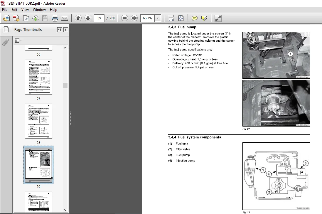
3 4 3 Fuel pump 3-1 5
3 4 4 Fuel system components 3-1 5
3 4 5 Bleeding the fuel system 3-1 6
3 4 6 Fuel tank filler cap 3-1 6
3 5 Hand throttle lever 3-1 7
4 Power train 4-1
4 1 Transmission 4-3
4 1 1 Removing the transmission 4-3
4 1 2 Installing the transmission 4-6
4 1 3 Drive train diagram- GC1 705 / GC1 710 4-7
4 1 4 Drive train diagram – GC1 71 5 / GC1 72 0 4-8
4 1 5 Input shaft assembly 4-9
4 1 6 Hydrostatic transmission assembly diagram 4-10
4 1 7 Complete drive train construction 4-1 1
4 1 8 Front transmission cover 4-1 2
4 1 9 Pump drive system 4-1 3
4 1 10 Transmission gear construction 4-1 4
4 1 1 1 Range gears 4-1 4
4 1 1 2 Four-wheel drive gear system 4-1 5
4 1 1 3 Disassembling the transmission 4-1 5
4 1 1 4 Inspecting the transmission parts 4-2 4
4 1 1 5 Assembling the transmission 4-2 4
4 1 1 6 Assembling guidelines of the transmission 4-2 5
4 1 1 7 Inspecting the shift linkages 4-2 6
4 1 1 8 Assembling the shift linkages 4-2 7
4 2 Power takeoff 4-2 8
4 2 1 Power takeoff operating controls 4-2 8
4 2 2 Power takeoff assembly construction 4-2 9
4 2 3 Power takeoff gear train components 4-3 0
4 2 4 Power takeoff relief valve 4-3 1
4 3 Power takeoff clutch 4-3 2
GC1705 I GC1710 I GC1715 I GC1720
4283491M1
4 4
4 5
4 6
4 7
Table of contents
4 3 1 Power takeoff clutch pack assembly view 4-3 2
4 3 2 Disassembling the power takeoff clutch pack 4-3 2
Rear power takeoff 4-3 4
4 4 1 Disassembling the power takeoff clutch pack 4-3 4
4 4 2 Assembling the rear power takeoff 4-3 5
Engine 4-3 6
4 5 1 Removing the engine 4-3 6
Ground speed controls 4-4 0
4 6 1 Range gear shift lever 4-4 0
4 6 2 Hydrostatic control pedals 4-4 0
4 6 3 Ground speed chart 4-4 1
4 6 4 Setting the cruise control lever 4-4 1
Hydrostatic Transmission 4-4 2
4 7 1 Hydrostatic transmission components 4-4 2
4 7 2 Hydrostatic transmission operating diagram in neutral position 4-4 5
4 7 3 Adjusting the hydrostatic transmission 4-4 6
4 7 4 Hydrostatic transmission linkage 4-4 8
4 7 5 Function 4-4 9
4 7 6 Valves 4-51
4 7 7 List of major components of hydrostatic transmission 4-54
4 7 8 Required tools for disassembly/assembly 4-55
4 7 9 Precautions for disassembly 4-59
4 7 10 Disassembling the hydrostatic transmission 4-59
4 7 1 1 Precautions before assembly 4-63
4 7 1 2 Assembling the hydrostatic transmission 4-63
4 7 1 3 Hydrostatic transmission Troubleshooting 4-74
5 Cab and platform 5-1
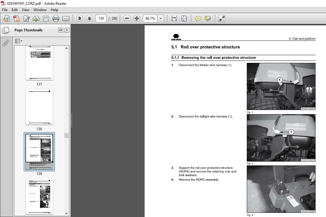
5 1 Roll over protective structure 5-3
5 1 1 Removing the roll over protective structure 5-3
5 1 2 Installing the roll over protective structure 5-3
5 2 Platform and fenders 5-4
5 2 1 Removing the platform and the fenders 5-4
5 2 2 Installing the platform and the fenders 5-7
5 3 Seat 5-8
5 3 1 Seat view 5-8
5 3 2 Rotating operation of the TLB type seat 5-9
5 3 3 Removing the seat 5-9
5 3 4 Installing the seat 5-10
6 Frame and axles 6-1
6 1 Removing the fuel tank 6-3
6 2 Front axle 6-4
6 2 1 Removing the front axle 6-4
6 2 2 Installing the front axle 6-6
6 2 3 Front axle view 6-7
6 2 4 Front axle final drive view 6-8
6 2 5 Front axle ring and pinion view 6-9
6 2 6 Front axle housing view 6-9
6 2 7 Disassembling the front axle 6-10
6 2 8 Assembling the front axle 6-1 4
6 2 9 Front axle oil 6-1 5
6 2 10 Checking the front axle oil level 6-1 5
6 2 1 1 Changing the front axle oil 6-1 6
6 2 1 2 Adjusting the front wheel alignment 6-1 6
GC1705/ GC1710/ GC1715/ GC1720
4283491M1
Table of contents
6 3 Rear axle and brakes 6-1 8
6 3 1 Rear axle view 6-1 8
6 3 2 Rear axle ring and pinion components 6-1 9
6 3 3 Disassembling the rear ring and pinion 6-2 0
6 3 4 Assembling the rear ring and pinion 6-2 5
6 3 5 Differential lock 6-2 5
6 3 6 Assembling the differential lock 6-2 6
6 3 7 Axle and brake components 6-2 7
6 3 8 Removing the rear axles and the brakes 6-2 9
6 3 9 Inspecting the rear axle and the brakes 6-3 2
6 3 10 Friction plates 6-3 2
6 3 1 1 Pressure Plate Assembly 6-3 2
6 3 1 2 Separator plate 6-3 3
6 3 1 3 Installing the rear axle and the brakes 6-3 3
6 3 1 4 Rear axle assembly guidelines 6-3 4
6 3 1 5 Brake pedal free play 6-3 5
6 3 1 6 Adjusting the brakes 6-3 5
6 3 1 7 Parking brakes 6-3 6
7 Electrical 7-1
7 1 Wiring harness 7-3
7 1 1 Wiring harness layout- chassis 7-3
7 1 2 Wiring harness layout – engine 7-4
7 2 Electrical system 7-5
7 2 1 Battery 7-5
7 2 2 Wiring / fuse arrangement 7-6
7 2 3 Neutral starting switches 7-8
7 2 4 Combination switch diagram 7-8
7 2 5 Main switch diagram 7-9
7 2 6 Spare power supply 7-9
7 3 Wiring diagram 7-10
7 3 1 Wiring diagram legend 7-10
7 3 2 Wiring diagram 7-1 2
7 4 Safety switches, fuses, and relays 7-1 4
7 4 1 Safety switches 7-1 4
7 4 2 Relays 7-1 5
7 4 3 Fuel shut off solenoid 7-1 6
7 4 4 Oil pressure sending unit 7-1 6
7 4 5 Water temperature sending unit 7-1 7
7 4 6 Fuel gauge sending unit 7-1 7
7 5 Instrument panel 7-1 8
7 5 1 Removing the instrument panel 7-1 8
7 5 2 Instrument panel components 7-1 8
8 Hydraulics 8-1
8 1 Hydraulic specifications 8-3
8 1 1 Hydraulic system diagram J type 8-4
8 1 2 Components and test ports 8-5
8 2 Joy stick valve {factory installed) 8-7
8 2 1 Remote valve with factory joystick 8-7
8 2 2 Remote valve hardline routing 8-8
8 2 3 Joy stick valve – major components 8-9
8 3 Operation Mechanism 8-1 1
8 3 1 Boom valve 8-1 1
8 3 2 Bucket valve 8-1 2
GC1705 I GC1710 I GC1715 I GC1720
4283491M1
8 4
8 5
8 6
Table of contents
8 3 3 Joystick linkage 8-1 4
Control valve 8-1 6
8 4 1 Control valve components 8-1 6
8 4 2 Control valve assembly 8-1 7
8 4 3 Control valve hydraulic circuit 8-18
8 4 4 Adjusting the control valve linkage 8-19
Lift cylinder 8-20
8 5 1 Lift cylinder components 8-20
8 5 2 Disassembling the lift cylinder 8-20
8 5 3 Inspecting the lift cylinder 8-23
8 5 4 Assembling the lift cylinder 8-23
Steering system 8-24
8 6 1 Steering wheel and steering valve 8-26
8 6 2 Removing the steering valve assembly 8-26
8 6 3 Inspecting the steering valve 8-27
8 6 4 Steering valve specifications 8-27
8 6 5 Assembling the steering valve 8-27
8 6 6 Steering cylinder 8-28
8 6 7 Steering free play 8-29
9 Machine systems 9-1
9 1 Mower deck 9-3
9 1 1 Mower deck general information 9-3
9 1 2 Mower identification plate 9-4
9 1 3 Safety and cutting height adjustment labels 9-5
9 1 4 Mower deck components 9-6
9 1 5 Installing the mower deck 9-7
9 1 6 Mower deck lift linkage 9-9
9 1 7 Adjusting the lift linkage 9-1 1
9 1 8 Removing the mower deck 9-1 2
9 1 9 Mower lubrication chart 9-1 3
9 1 1 0 V-belt inspection 9-1 4
9 1 1 1 Replacing the v-belt 9-1 5
9 1 1 2 Removing the blade 9-1 6
9 1 1 3 Installing the standard blade 9-1 6
9 1 1 4 Shimming the standard blade 9-1 7
9 1 1 5 Installing the mulching blade 9-1 7
9 1 1 6 Shimming the mulching blade 9-18
9 1 1 7 Blade wear 9-18
9 1 18 Inspection of gauge wheels 9-18
9 1 19 Inspection of rollers 9-19
9 1 20 Cleaning under the belt covers 9-19
9 1 21 Checking the gearbox oil level 9-19
9 1 22 Changing the gearbox oil 9-19
9 1 23 Repairing the gearbox 9-20
9 1 24 Adjusting the backlash 9-21
9 1 25 Outer spindles 9-22
9 1 26 Center (gearbox) spindle 9-22
9 1 27 Repairing the spindles 9-23
10 Index lndex-1
MASSEY FERGUSON EU TRACTOR MFGC SERIES GC1705 GC1710 GC1715 GC1720 SUB-COMPACT SERVICE MANUAL – PDF DOWNLOAD:
PLEASE NOTE:
- This is the SAME manual used by the dealers to troubleshoot any faults in your vehicle. This can be yours in 2 minutes after the payment is made.
- Contact us at [email protected] should you have any queries before your purchase or that you need any other service / repair / parts operators manual.
S.V