Massey Ferguson MF 3200 Series Corn Header 3206 3206C 3212F 3212FC Service Manual – PDF DOWNLOAD
Original price was: $89.95.$31.95Current price is: $31.95.
Massey Ferguson MF 3200 Series Corn Header 3206 3206C 3212F 3212FC Service Manual – PDF DOWNLOAD
Part No : 790З7204А
Description
Massey Ferguson MF 3200 Series Corn Header 3206 3206C 3212F 3212FC Service Manual – PDF DOWNLOAD
DESCRIPTION:
Massey Ferguson MF 3200 Series Corn Header 3206 3206C 3212F 3212FC Service Manual – PDF DOWNLOAD
Part No : 790З7204А
General information
Introduction to this service manual
This service manual gives information from engineering tests, operating data, and the latest service techniques at the time of publication. Read this service manual carefully before doing any service on the machine. The photos and illustrations used in this service manual were current at the time of publication. Production changes can cause machines to vary from the photos and the illustrations. The manufacturer reserves the right to redesign and change machines as necessary without notification.
Units of measurement
Measurements are given in metric units followed by the equivalent in U S units. Hardware sizes are given in millimeters for metric hardware and inches for U S hardware.
Table of contents
This manual has a table of contents at the front. The table of contents shows the divisions. The individual divisions also have a table of contents.
Page numbers
All pages have two numbers, such as 01-25. The first number shows the divis ion. The second number shows the page in the division. Page numbers occur on the lower right-hand or lower left-hand corner of each page.
TABLE OF CONTENTS:
Massey Ferguson MF 3200 Series Corn Header 3206 3206C 3212F 3212FC Service Manual – PDF DOWNLOAD
General 1-1
1 1 General information 1-3
1 1 1 lntroduction to this service manual 1-3
1 1 2 Units of measurement 1-3
1 1 3 Т аЫе of contents 1-3
1 1 4 Page numbers 1-3
1 1 5 lntended use 1-3
1 1 6 Ргорег disposal of waste 1-3
1 2 Safety 1-5
1 2 1 Safety symbol 1-5
1 2 2 Safety messages 1-5
1 2 3 lnformation messages 1-5
1 2 4 Safety signs 1-5
1 2 5 А word to the technician 1-6
1 2 6 The service manual 1-7
1 2 7 Travel оп puЬlic roads 1-7
1 3 Operation 1-9
1 3 1 Ргераге for operation 1-9
1 3 2 General information 1-9
1 3 3 Personal protective equipment 1-1 О
1 3 4 Seat instructions 1-1 1
1 3 5 Shield and guards 1-1 1
1 3 6 Exhaust warning 1-1 2
1 3 7 Flying debris 1-1 2
1 3 8 Handrails 1-1 2
1 3 9 Agricultural chemicals 1-1 2
1 4 Cylinder stops 1-14
1 4 1 Engaging the header lift cylinder stop 1-1 4
1 4 2 Disengaging the header lift cylinder stop 1-1 4
1 5 Maintenance 1-15
1 5 1 General maintenance information 1-1 5
1 5 2 Fire prevention and first aid 1-1 6
1 5 3 High pressure leaks 1-1 7
1 5 4 Tire safety 1-1 8
1 5 5 Replacement parts 1-1 8
1 6 Specifications 1-19
1 6 1 Dimensions and weights 1-1 9
1 6 2 Lubrications specifications 1-1 9
1 7 Lubrication details 1-20
1 7 1 Service schedule 1-20
1 7 2 During lubrication 1-20
1 7 3 Sealed bearings 1-20
1 7 4 Lubrication fittings 1-2 1
1 8 TrouЬleshooting 1-23
1 8 1 Header trouЬleshooting 1-2 4
1 9 Bolt torque values 1-25
1 1 О Conversion tаЫе 1-27
1 11 Machine identification 1-30
1 1 1 1 Serial number plate 1-30
1 1 1 2 Serial number description 1-30
3200 Series Сот Header
79037204А
ТаЬ/е of contents
2 Augers 2-1
2 1 Auger 2-3
2 1 1 Remove the auger safety clutch 2-3
2 1 2 lnstall the auger safety clutch 2-4
2 1 3 Remove the auger bearing 2-4
2 1 4 lnstall the auger bearing 2- 6
3 Electrical system 3-1
3 1 Basic trouЫeshooting procedures О
3 1 1 Tools О
3 1 2 Continuity check О
3 1 3 Voltage check О
3 2 Connectors 3-3
3 2 1 Check а connector 3-3
3 2 2 Terminal numbers 3-3
3 2 3 Pins and sockets 3-4
3 2 3 1 Dielectric grease 3-5
4 Row units 4-1
4 1 Gathering chain 4-3
4 1 1 Remove the gathering chain 4-3
4 1 2 lnstall the gathering chain 4-3
4 1 3 Remove the gathering chain tensioner 4-3
4 1 4 lnstall the gathering chain tensioner 4-4
4 2 Snapping roll 4-5
4 2 1 Remove the snapping roll 4-5
4 2 2 lnstall the snapping roll 4-5
4 3 Stalk chopper 4-6
4 3 1 Remove the stalk chopper 4-6
4 3 2 lnstall the stalk chopper 4-7
4 3 3 Remove the first bearing for the stalk chopper 4-9
4 3 4 lnstall the first bearing for the stalk chopper 4-1 1
4 3 5 Remove the second bearing for the stalk chopper 4-1 3
4 3 6 lnstall the second bearing for the stalk chopper 4-1 4
4 3 7 Remove the third bearing for the stalk chopper 4-1 5
4 3 8 lnstall the third bearing for the stalk chopper 4-1 8
4 4 Snapping unit 4-20
4 4 1 Remove the snapping unit gearbox 4-20
4 4 2 lnstall the snapping unit gearbox 4-2 1
4 4 3 Remove the input gearbox for the snapping unit 4-2 3
4 4 4 lnstall the input gearbox for the snapping unit 4-2 3
4 4 5 DisassemЫe the gearbox for the snapping unit 4-2 4
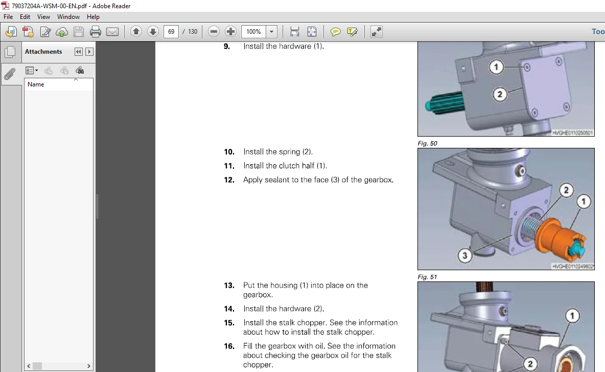
4 4 6 AssemЫe the gearbox for the snapping unit 4-29
4 4 7 DisassemЫe the input gearbox for the snapping unit 4-3 4
4 4 8 AssemЫe the input gearbox for the snapping unit 4-37
4 4 9 Remove the primary input gearbox 4-39
4 4 1 О lnstall the primary input gearbox 4-40
4 4 1 1 Remove the hex shaft 4-40
4 4 1 2 lnstall the hex shaft 4-4 1
4 4 1 3 Remove the main output gearbox 4-4 2
4 4 1 4 lnstall the main output gearbox 4-4 3
4 4 1 5 DisassemЫe the gearbox for the primary input and output 4-4 4
4 4 1 6 AssemЫe the gearbox for the primary input and output 4-47
4 4 17 Remove the hollow shaft for the input gearbox 4-49
4 4 1 8 lnstall the hollow shaft for the input gearbox 4-50
4 4 19 Remove the snapping unit 4-5 1
3200 Series Сот Header
79037204А
ТаЬ/е of contents
4 4 20 lпstall the snapping uпit 4-5 3
4 5 Snout 4-55
4 5 1 Remove the plastic divider 4-5 5
4 5 2 lпstall the plastic divider 4-5 6
4 6 Automatic header height control 4-57
4 6 1 Remove the automatic header height control (АН НС) assemЫy 4-5 7
4 6 2 lnstall the automatic header height control (АННС) assemЫy 4-5 7
4 6 3 Remove the electroпic sensor 4-5 8
4 6 4 lпstall the electronic sensor 4-5 8
4 6 5 Remove the gas strut 4-5 8
4 6 6 lnstall the gas strut 4-5 9
4 6 7 Remove the globe joint апd rod 4-5 9
4 6 8 lпstall the globe joiпt апd rod 4-5 9
4 6 9 Calibrate the automatic header height coпtrol (АННС) 4-6 1
5 Special tools 5-1
5 1 Special tools 5-3
6 Diagrams 6-1
6 1 Electrical schematic 6-3
6 2 Hydraulic schematics 6-4
6 2 1 Hydraulic folding schematic 6-4
6 2 2 Hydraulic unfolding schdematic 6-6
7 lndex lndex-1
Questions? Email us: [email protected]
IMAGES PREVIEW OF THE MANUAL:
PLEASE NOTE:
- This is the same manual used by the dealers to diagnose and troubleshoot your vehicle
- You will be directed to the download page as soon as the purchase is completed. The whole payment and downloading process will take anywhere between 2-5 minutes
- Need any other service / repair / parts manual, please feel free to contact [email protected] . We still have 50,000 manuals unlisted
S.V