Massey Ferguson MF 3300 Series Corn Header 3308 3312 3316 Service Manual – PDF DOWNLOAD
Original price was: $89.95.$28.95Current price is: $28.95.
Massey Ferguson MF 3300 Series Corn Header 3308 3312 3316 Service Manual – PDF DOWNLOAD
Description
Massey Ferguson MF 3300 Series Corn Header 3308 3312 3316 Service Manual – PDF DOWNLOAD
DESCRIPTION:
Massey Ferguson MF 3300 Series Corn Header 3308 3312 3316 Service Manual – PDF DOWNLOAD
General information
Introduction to this service manual
This service manual gives information from engineering tests, operating data, and the latest service techniques at the time of publication. Read this service manual carefully before doing any service on the machine. The photos and illustrations used in this service manual were current at the time of publication. Production changes can cause machines to vary from the photos and the illustrations. The manufacturer reserves the right to redesign and change machines as necessary without notification.
Units of measurement
Measurements are given in metric units followed by the equivalent in U S units. Hardware sizes are given in millimeters for metric hardware and inches for U S hardware.
Table of contents
This manual has a table of contents at the front. The table of contents shows the divisions. The individual divisions also have a table of contents.
Page numbers
All pages have two numbers, such as 01-25. The first number shows the divis ion. The second number shows the page in the division. Page numbers occur on the lower right-hand or lower left-hand corner of each page.
TABLE OF CONTENTS:
Massey Ferguson MF 3300 Series Corn Header 3308 3312 3316 Service Manual – PDF DOWNLOAD
1 General 1-1
1 1 General information 1-3
1 1 1 lntroduction to this service manual 1-3
1 1 2 Units of measurement 1-3
1 1 3 ТаЫе of contents 1-3
1 1 4 Page numbers 1-3
1 1 5 lntended use 1-3
1 1 6 Ргорег disposal of waste 1-3
1 2 Safety 1-5
1 2 1 Safety symbol 1-5
1 2 2 Safety messages 1-5
1 2 3 lnformation messages 1-5
1 2 4 Safety signs 1-5
1 2 5 А word to the technician 1-6
1 2 6 T he service manual 1-7
1 2 7 Operation 1-7
1 2 7 1 Ргераге for operation 1-7
1 2 7 2 General information 1-7
1 2 7 3 Personal protective equipment 1-8
1 2 7 4 Seat instructions 1-9
1 2 7 5 Shield and guards 1-9
1 2 7 6 Exhaust warning 1-10
1 2 7 7 Flying debris 1-10
1 2 7 8 Handrails 1-10
1 2 7 9 Agricultural chemicals 1-10
1 2 8 Travel оп puЬlic roads 1-1 1
1 2 9 Maintenance 1-1 2
1 2 9 1 General maintenance information 1-1 2
1 2 9 2 Fire prevention and first aid 1-1 4
1 2 9 3 High pressure leaks 1-1 5
1 2 9 4 T ire safety 1-1 5
1 2 9 5 Replacement parts 1-1 6
1 3 Cylinder stops 1-17
1 3 1 Engage the header lift cylinder stop 1-1 7
1 3 2 Disengage the header lift cylinder stop 1-1 7
1 4 Specifications 1-18
1 4 1 Dimensions and weights 1-1 8
1 4 2 Header speeds 1-1 8
1 4 3 Lubrication specifications 1-1 8
1 5 Lubrication details 1-19
1 5 1 During lubrication 1-1 9
1 5 2 Sealed bearings 1-1 9
1 5 3 Lubrication fittings 1-1 9
1 5 3 1 Torque limiter 1-1 9
1 5 3 2 Conveyor drive slip clutch 1-20
1 5 3 3 Left driveline 1-20
1 5 3 4 Right driveline 1-2 1
1 6 Header trouЫeshooting 1-23
1 7 Bolt torque values 1-24
1 8 Machine identification 1-26
1 8 1 Serial number plate 1-2 6
3300 Series Сот Header
4283583М3
ТаЬ/е of contents
1 8 2 Serial number description 1-2 6
1 9 Connect to comblne 1-27
1 10 Disconnect from comblne 1-30
1 11 Header description 1-32
1 1 2 Header configuration 1-33
1 1 2 1 Change header configuration from transverse to axial 1-3 3
1 1 2 2 Change header configuration from axial to transverse 1-3 5
2 Frame 2-1
2 1 Tilt frame 2-3
2 1 1 Remove the tilt frame 2-3
2 1 2 lnstall the tilt frame 2-4
3 Auger 3-1
3 1 Auger 3-3
3 1 1 Remove the auger drive chain 3-3
3 1 2 lnstall the auger drive chain 3-4
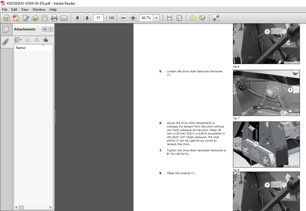
3 1 3 Adjust the auger drive chain 3-4
3 1 4 Remove the auger 3-6
3 1 5 lnstall the auger 3-6
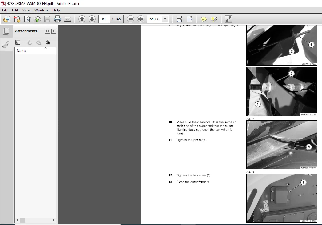
3 1 6 Adjust the auger 3-7
3 1 7 Remove the auger stripper angles 3-10
3 1 8 lnstall the auger stripper angles 3-1 1
3 1 9 Remove the auger рап 3-1 1
3 1 10 lnstall the auger рап 3-1 1
4 Drive system 4-1
4 1 Drive system 4-3
4 1 1 Remove the drive shaft 4-3
4 1 2 lnstall the drive shaft 4-4
4 2 Driveline 4-7
4 2 1 Remove the implement driveline 4-7
4 2 2 DisassemЫe the driveline 4-7
4 2 3 lnspect the driveline components 4-1 1
4 2 4 AssemЬle the driveline 4-1 1
4 2 5 lnstall the implement driveline 4-1 4
5 Electrical system 5-1
5 1 Basic electrical trouЫeshooting 5-3
5 1 1 Basic trouЫeshooting procedures 5-3
5 1 2 Tools 5-4
5 1 3 Continuity check 5-4
5 1 4 Voltage check 5-5
5 2 Connectors 5-6
5 2 1 Examine а connector 5-6
5 2 2 Terminal numbers 5-6
5 2 3 Dielectric grease 5-7
5 2 4 Pins and sockets 5-7
5 2 5 Replace а Packard connector 5-8
5 2 6 Replace an АМР connector 5-8
5 2 7 Replace а Power Cord connector 5-9
5 2 8 Replace а Deutsch connector 5-9
5 3 Electrical harness 5-11
6 Shielding 6-1
6 1 Shielding 6-3
3300 Series Сот Header
Remove the inner gathering assemЫy 6-3
lnstall the inner gathering assemЫy 6-3
Adjust the inner gathering assemЫy height 6-4
Remove the snout 6-5
lnstall the snout 6-6
Adjust the snout height 6-7
Remove the hood 6-8
lnstall hood 6-8
Adjust hood clearance 6-9
7 Row units 7-1
7 1 Row units 7-3
7 1 1 Remove the row unit gearbox 7-3
7 1 2 lnstall the row unit gearbox 7-3
7 1 3 Examine row unit gearbox for lubricant 7-3
7 1 4 Add lubricant to the row unit gearbox 7-4
7 1 5 Remove the chopper gearbox 7-5
7 1 6 lnstall the chopper gearbox 7-5
7 1 7 Examine chopper gearbox for lubricant 7-5
7 1 8 Add lubricant to the chopper gearbox 7-6
7 1 9 Remove the row unit 7-6
7 1 10 DisassemЫe the row unit 7-9
7 1 1 1 AssemЫe the row unit 7-9
7 1 1 2 lnstall the row unit 7-9
7 1 1 3 Remove the row unit drive 7-1 1
7 1 1 4 lnstall the row unit drive 7-1 2
7 1 1 5 Adjust the row unit drive chain 7-1 3
7 1 1 6 Check drive chain reservoir for lubricant 7-1 4
7 1 1 7 Add lubricant to the drive chain reservoir 7-1 5
7 1 1 8 Remove the row unit torque limiter 7-1 5
7 1 1 9 DisassemЫe the row unit torque limiter 7-1 7
7 1 20 AssemЫe the row unit torque limiter 7-1 7
7 1 21 lnstall the row unit torque limiter 7-1 8
7 1 22 Remove the stripper plates 7-1 9
7 1 23 lnstall the stripper plates 7-21
7 1 24 Remove the snapping rolls 7-22
7 1 25 lnstall the snapping rolls 7-23
7 1 26 Remove the chopping knives 7-25
7 1 27 lnstall the chopping knives 7-25
7 2 Gathering chain 7-27
7 2 1 Gathering chain length 7-27
7 2 2 Adjust the gathering chain 7-27
7 2 3 Replace the gathering chain 7-27
7 3 Stripper plates 7-29
7 3 1 Adjust the fixed stripper plates 7-29
7 3 2 Stripper plate indicator 7-29
7 3 3 lndex stripper plates 7-29
7 3 4 Stripper plate cleaning 7-30
7 4 Snapping roll Ьlades 7-31
7 4 1 Change snapping roll Ыades 7-3 1
7 5 Grass knives 7-32
7 5 1 Adjust the grass knives 7-3 2
8 Diagrams 8-1
8 1 Wiring diagram 8-3
9 lndex lndex-1
Need help? Contact: [email protected]
IMAGES PREVIEW OF THE MANUAL:
PLEASE NOTE:
- This is the SAME exact manual used by your dealers to fix your vehicle.
- The same can be yours in the next 2-3 mins as you will be directed to the download page immediately after paying for the manual.
- Any queries / doubts regarding your purchase, please feel free to contact [email protected]
S.V