Massey Ferguson MF 5400 Series Workshop Manual – PDF DOWNLOAD
Original price was: $51.95.$34.95Current price is: $34.95.
Massey Ferguson MF 5400 Series Workshop Manual
Description
Massey Ferguson MF 5400 Series Workshop Manual
FILE DETAILS:
Massey Ferguson MF 5400 Series Workshop Manual
Language: English
Size: 93.5 MB
Pages: 886
Format: PDF
Downloadable: YES
DESCRIPTION:
Massey Ferguson MF 5400 Series Workshop Manual
General:
The purpose of this manual is to assist Distributors and Dealers in the efficient installation. maintenance and repair or MASSEY FERGUSON machinery. Carrying omthe procedures as detailed. together with the use at specral tools where appropriate. wrll enable the opera- lions to be compiated within the time stated in the repair time schedule.
Using the manual :
For quick reference, each chapter of the manual is preceded by a table of contents listing the sections included in that chapter.
Repairs and replacements:
When parts have lobe replaced. it is csmnlial that only genuine MASSEY FERGUSON parts are used. Attention is particularly drawn to tho lollnwtng points concerning repairs and the fitting oi replacement parts and accessories. Safety lcalures emboded in the tractor may be impaired if other than genuine parts are fitted. in certain territories. legislation prohibits the fitting oi parts not to the tractor manulacturer’s specification, Torque wrench setting ligures given in the Workshop Manual must be strictly adhered to. Locking devices must be titted where specified. it the efficiency of a locking device is impaired during removal it must ‘oc renewed. the tractor warranty may be invalidated by the titling of other than genuine MASSEY FERGUSON parts. All MASSEY FERGUSON replacement parts have the lull backing of the manulacturer’s warranty. MASSEY FERGUSON Distributors and Dealers are obliged to suppty only genurne servrce parts.
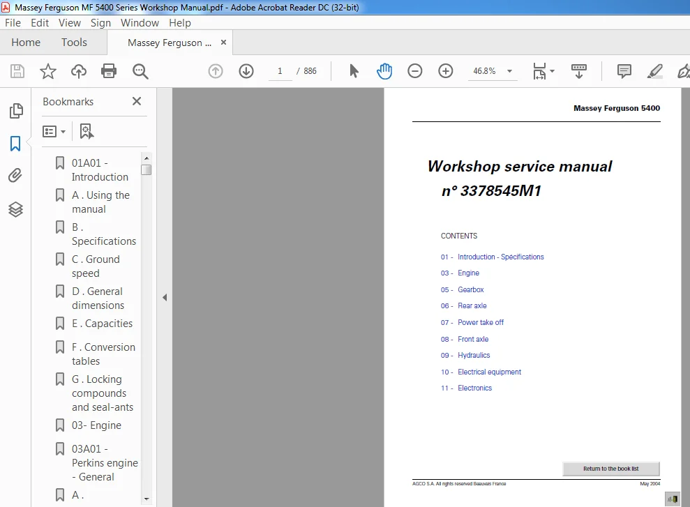
TABLE OF CONTENTS:
Massey Ferguson MF 5400 Series Workshop Manual
01A01 – Introduction 5
A Using the manual 7
B Specifications 8
C Ground speed 8
D General dimensions 18
E Capacities 21
F Conversion tables 21
G Locking compounds and seal-ants 23
03- Engine 25
03A01 – Perkins engine – General 27
A Introduction 29
B Specifications and standards 29
C Main characteristics 30
05- Gearbox 37
05A02 – General – GBA20 with Power Shuttle 39
A General 41
B Construction and description 47
C Operation 48
D Specifications of the GBA20 transmission assembly with Power Shuttle 50
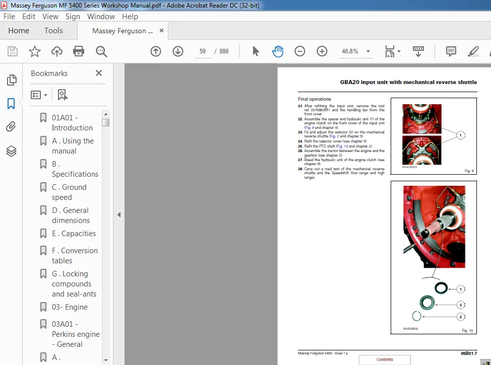
05B01 – GBA20 input unit with mechanical reverse shuttle 55
A General 55
B Removing and refitting the input unit 56
C Service tools 60
05B02 – Input unit – GBA20 with Power Shuttle 61
A General 63
B Preliminary operations 64
C Removal 65
D Refitting 67
E Adjusting the progressivity sensor 68
F Final operations 68
G Service tools 69
05C01 – GBA20 mechanical reverse shuttle 71
A General 73
B Operation 78
C Preliminary operations 80
D Disassembling and reassembling the reverse shuttle 80
E Shimming the secondary shaft 84
F Final operations 85
05C02 – GBA20 Power Shuttle 87
A General 89
B Removing and refitting the forward clutch 99
C Disassembling and reassembling the forward clutch 100
D Shimming the forward clutch 104
E Disassembling and reassembling the reverse clutch 105
F Disassembling and reassembling the driving pinion 110
G Service tools 114
05D02 – GBA20 Speedshift with Power Shuttle 117
A General 119
B Operation 125
C Preliminary operations 127
D Removing and disassembling the front cover 128
E Removing, splitting and disas-sembling the planet carrier assembly 130
F Disassembling the hydraulic cover 132
G Assembling the planet carrier 133
H Refitting the hydraulic cover 134
I Assembling the planet carrier 135
J Assembling and refitting the front cover 136
K Final operations 137
05E02 – Selector cover – GBA20 with Power Shuttle 139
A General 141
B Operation 147
C Removing and refitting the cover 149
D Disassembling and reassembling the selector mechanisms 153
E Fitting and adjusting the gear linkage 156
05F01 – GBA20 selector rails with mechanical reverse shuttle 159
A General 161
B Servicing guide 167
C Creeper fork 169
D Hare / Tortoise fork and lock- 1st /2nd – 3rd / 4th fork assembly and selector rail 173
E Mechanical reverse shuttle selector 180
F Service tools 184
05F02 – GBA20 selector rail with Power Shuttle 185
A General 187
B Servicing guide 193
C Creeper fork 195
D Hare / Tortoise fork and lock- 1st /2nd – 3rd / 4th fork assembly and selector rail 199
E Service tools 207
05G02 – GBA20 output shaft with Power Shuttle 209
A General 211
B Preliminary operations 215
C Removing and refitting the selector rail and the forks 215
D Removing, refitting and shim-ming the shaft 216
E Final operations 220
05H02 – GBA20 mainshaft with Power Shuttle 221
A General 223
B Preliminary operations 227
C Disassembling and reassembling the shaft 228
D Final operations 230
E Service tools 231
05I02 – GBA20 layshaft with Power Shuttle 233
A General 235
B Preliminary operations 237
C Removing and refitting the shaft and pinion assembly 237
D Removing and refitting pinions 238
E Replacing the taper roller bear-ings and the layshaft 239
F Shimming the pinions 239
G Shimming the shaft 240
H Final operations 241
I Service tool 242
05J01 – GBA20 Creeper unit 243
A General 245
C Removing the creeper unit and the ring gear 248
E Reassembling the planet carrier, refitting the ring gear and the unit 249
F Final operations 249
G Adjusting the control 250
06- Rear axle 251
06A01 – General – GPA20 operation 253
A General 255
B Centre housing assembly 255
06B01 – GPA20 Normal Duty Trumpet housings 259
A General 261
B Trumpet assembly 264
C Planet carrier 266
D Bearings and seals 267
E Preloading the axle shaft bear-ings 268
F Replacing a lug stud 269
06B02 – GPA20 Heavy Duty Trumpet housings 271
A General 273
B Trumpet assembly 276
C Planet carrier 278
D Bearings and seals 279
E Preloading the axle shaft bear-ings 280
F Replacing a wheel stud 281
06C01 – GPA20 brake piston 283
A General 285
B Disassembly 286
C Reassembly 287
06D01 – GPA20 handbrake unit and control 289
A General 291
B Operation 291
C Disassembly 295
D Reassembly 297
E Assembling and adjusting the control 299
06E01 – GPA20 differential 301
A General 303
B Removing the left-hand flange and differential lock assembly 307
C Disassembling and reassembling the differential lock assembly 308
D Refitting the left-hand flange and the differential lock assembly 309
E Removing the differential assembly 311
F Disassembling the differential assembly and the ring gear 312
G Removing and disassembling the drive pinion 313
H Reassembling the ring gear and differential assembly 314
I Adjusting the bevel gear distance, refitting and shimming of the drive pinion 315
J Refitting and shimming of the differential assembly 318
K Adjusting and checking the back-lash 322
L Service tools 324
06F01 – GPA20 hitch / Linkage 325
A General 327
B Removal 330
C Disassembly 331
D Reassembly 332
E Refitting 334
F Rear Hitch 336
G Presentation of the hitch 336
H Disassembling and reassembling a lift ram 339
06G01 – GPA20 hitch hooks 341
A General 343
B Presentation of the different hitch hooks 344
C Adjusting automatic hook tie-rods and controls 347
D Operating principle of the Dromone retractable hook 349
06H01 – GPA20 rear wheels / hubs 351
A General 353
B Description of rear axle wheel assembly 353
C Changing wheel track spacing 354
D Replacing a wheel stud 356
07- Power take off 357
07A01 – General – GPA20 operation 359
A General 361
B Existing power take-off types 363
07B01 – Intermediate shaft – Driving pinions – GPA20 brake 369
A General 371
B Operation 371
C 2-speed PTO (without shimming) 375
D 2-speed PTO (with shimming) 377
E 4-speed economy PTO (without shimming) 379
F 4-speed LSPTO (with shimming) 382
G Assembling and adjusting the 4-speed LSPTO control 384
07C01 – GPA20 removable shaft 385
A General 387
B Replacing the 540 or 1000 rpm shaft 390
C Removing and refitting the rear bearing 390
D Disassembling and reassembling the rear bearing 391
E Disassembling and assembling the 540 and 1000 rpm pinions and the front bearing 392
07D01 – GPA20 shiftable shaft 393
A General 395
C Removing and refitting the rear bearing 400
D Disassembling and reassembling the rear bearing 401
E Disassembling and reassembling the pinions (540 and 1000 rpm) and the front shaft bearing 402
F Controls 404
G Flange shaft 405
H Shaft with reinforced sealing 407
07E01 – GPA20 – GSPTO 413
A General 415
B Operation 415
C Disassembling the power take off (2WD version) 419
D Reassembling the power take off (2WD version) 421
E Disassembling the power take off (4WD version) 424
F Reassembling the power take off (4WD version) 425
G Assembling and adjusting the control 426
08- Front axle 427
A General description 431
B Characteristics and dimensions 435
C Product identification 437
08E01 – GPA20 multidisc 4WD clutch 439
A General 441
B Operation 441
C Removing the clutch assembly 445
D Disassembling the clutch 446
E Reassembling the clutch 447
F Refitting the clutch assembly 448
G Locally made tools 450
09- Hydraulics 451
09A01 – Description of circuit open centre 57 l/mn 453
A General 455
B Low flow rate, low pressure circuit 455
C Layout of main components of Power shuttle and Speedshift circuit 457
D Layout of main components of Mechanical reverse shuttle Speedshift circuit 459
E High flow rate, high pressure circuit 460
F Diagram of mechanical reverse shuttle Speedshift 460
G Diagram of Power shuttle Speedshift 462
09B01 – Right-hand cover – 57l/min Open Centre 465
A General 467
B Identification of channels and ports 472
C Removing and refitting the cover 474
D Disassembling and reassembling the high pressure valve 477
E Disassembling and reassembling the cover 478
F Removing and refitting the pump 479
G Disassembling and reassembling the pump 481
H Adjusting the engine speed sensor 484
09C01 – Left-hand cover – 57l/min Open Centre 485
A General 487
B Removing – Refitting 488
09D01 – Trailer braking – Open centre 491
A General 493
B Removing and refitting the brake spool valve 496
C Operation, trailer brakes released and partial braking 499
D Partial and maximum trailer braking 501
E Version without trailer braking 502
09E01 – Auxiliary spool valve 503
A General 505
B Layout of channels and ports 510
C Operating and adjusting the flow divider 512
D Removing and refitting spool valves 514
E 3-position spool valve, SA / DA with spring loaded return to neutral 516
F 3-position spool valve, SA / DA with automatic return to neutral 518
G 3-position SA / DA spool valve with non-return valve and auto-matic return 520
H 4-position DA spool valve, with automatic return to neutral and floa-ting position 522
I Fitting and adjusting a control cable 524
09F01 – Lift control spool valve – Open Centre 527
A General 529
B Layout of components and iden-tification of ports 530
C Neutral position 532
D Lifting position 536
E Lowering position 538
F Shock valve 540
G Removing and refitting the spool valve 542
09H01 – 17 bar – 5 bar and 1 5 bar valves – Open centre 545
A General 547
B Description of the 17 bar low pressure valve 549
C Removing – refitting and disas-sembling – reassembling the 17 bar valve 551
D Adjusting the 17 bar valve 552
E Operation of the cooling system 553
F Assembling the 5 bar valve 554
G Description of the 1 5 bar lubrica-ting valve 554
H Removing – refitting and disas-sembling – reassembling the 1 5 bar valve 555
09I01 – Unassisted brake master cylinders 557
A General 559
B Layout of hydraulic lines 560
C Practical servicing advice 564
D Single circuit master cylinders (without trailer brake) 565
E Double circuit master cylinders (with trailer brake) 566
F Adjusting brake pedals 568
G Bleeding the main brake circuit 569
H Bleeding the trailer brake circuit 571
09I02 – Assisted brake master cylinders 573
A General 575
B Layout of hydraulic lines 577
C Practical servicing advice 583
D Brake master cylinders 583
E FTE valve 585
F Adjusting brake pedals 587
G Bleeding the main brake circuit 588
H Bleeding the trailer brake circuit 591
09J01 – GBA20 Power Shuttle control unit 593
A General 595
B Presentation of control unit and hydraulic lines 596
C Power Shuttle control 596
D Speedshift control 599
E Explanation of Speedshift ratios 601
F Removing – Refitting the control unit 602
09K01 – 57 l/min Open Centre tests 603
A General 605
B High flow rate circuit 606
C Low flow rate circuit 611
10- Electrical equipment 623
10A01 – Fuse box and relays 625
A Fuse box 627
B Relays – Europe 629
C Relays – North America 631
D Relays – Germany 633
10A02 – GBA20 electronic equipment 635
A General 637
B Cab equipment 639
C Engine equipment 661
D Transmission 673
E Bulb types 695
F Lighting 701
G Calculator supply 737
11- Electronics 743
11B10 – AUTOTRONIC 5 – Description 745
A General 747
B Autotronic5 status flowcharts 748
C Autotronic5 connector pin allo-cation 751
D Automatic responses of the Autotronic5 753
E Power Shuttle principles 755
GUF511 – AUTOTRONIC 5 – PowerShuttle – Programming and setting parameters 757
A Programming 759
B Setting parameters 764
GUF512 – AUTOTRONIC 5 – PowerShuttle – Tests and diagnostics 769
A Autotronic5 statuses 771
B Gearbox function 772
C Power Take-Off function 776
GUF513 – AUTOTRONIC 5 – PowerShuttle – Error codes 779
A Reading error codes 781
B List of error codes 784
C Analysing components and their error codes 786
D Analysing other error codes 799
GUF514 – AUTOTRONIC 5 – PowerShuttle – Calibration and adjustments 801
GUF514 – AUTOTRONIC 5 – PowerShuttle – Calibration and adjustments 801
A Calibrating the Power Shuttle 803
B Adjusting the Power Shuttle progressive shifting 806
C Adjusting the manoeuvring pedal 808
D Calibrating the (manoeuvring) clutch pedal 810
GUF515 – AUTOTRONIC 5 – PowerShuttle – Electrical diagrams 811
A General 813
B Electrical diagrams 815
11C10 – ELECTRONIC LINKAGE – Description 837
A Description 839
B Console 841
C Electronic calculator EHRB connector pin allocation 844
11C12 – ELECTRONIC LINKAGE – Tests and diagnostics 847
A Electronic Linkage component testing and diagnostics 849
11C13 – ELECTRONIC LINKAGE – Error codes 853
A Reading error codes 855
B List of error codes 856
C Analysing components and their error codes 857
11C14 – ELECTRONIC LINKAGE – Adjustment 869
A Adjusting the position sensor 871
11C15 – ELECTRONIC LINKAGE – Electrical diagrams 873
A General 875
Untitled 877
MASSEY FERGUSON MF 5400 SERIES WORKSHOP MANUAL – PDF DOWNLOAD:
IMAGES PREVIEW OF THE MANUAL:
PLEASE NOTE:
- This is the SAME exact manual used by your dealers to fix your vehicle.
- The same can be yours in the next 2-3 mins as you will be directed to the download page immediately after paying for the manual.
- Any queries / doubts regarding your purchase, please feel free to contact [email protected]Massey Ferguson MF 5400 Series Workshop Manual